Water air HONDA CR-V 2000 RD1-RD3 / 1.G User Guide
[x] Cancel search | Manufacturer: HONDA, Model Year: 2000, Model line: CR-V, Model: HONDA CR-V 2000 RD1-RD3 / 1.GPages: 1395, PDF Size: 35.62 MB
Page 931 of 1395
Bleeding
CAUNON:
. Do not spill brake tluid on the vehicle. it may damage
the paint; if brake fluid does contaqt th€ paint, wash
it otf immodiately with water.
. Maks sure no dirt oy other forsign matter is allowsd
to contaminate the brake fluid.
NOTE:
. Do not reuse the drained fluid.
. Always use Genuine Honda DOT 3 Brake Fluid. Using
a non-Honda brake fluid can cause corrosion and
decrease the life of the svstem.
. The reservoir on the master cylinder must be at the
MAX (upper) level mark at the start of bleeding pro-
cedure and checked after bleeding each brake caliper
and wheel cylinder. Add fluid as required.
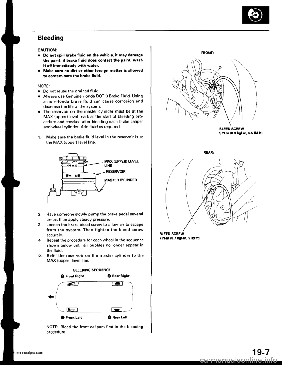
1, Make sure the brake fluid level in the reservoir is at
the MAX (uDDer) level line.
MAX {UPPER) LEVELLINE
RESERVOIR
MASTER CYLINDER
2.
3.
Have someone slowly pump the brake pedal several
times, then apply steady pressu.e.
Loosen the brake bleed screw to allow air to escape
from the system. Then tighten the bleed screw
securely.
Repeat the procedure for each wheel in the sequence
shown below until air bubbles no longer appear in
the tluid.
Refill the reservoir on the master cvlinder to the
MAX (upper) level line.
ALEEDING SEOUENCE:
O Front RightGt Rear Right
O Front LeflO Rear Left
NOTE: Bleed the front calipers first in the bleeding
procedure.
4.
FRONT:
BLEEO SCREW7 N.m (0.? kgf.m, 5 lbf.ftl
19-7
www.emanualpro.com
Page 936 of 1395
Front Brake Caliper
Disassembly/Reassembly
. Never use an air hose or dry brush to clean brake assemblies.
. Use an OSHA approved vacuum cleaner to avoid breathing brake dust.
. Contaminated brake discs or pads reduce stopping ability.
. When reusing the pads, always reinstallthe brake pads in their original positions to prevent loss ol braking efficiency.
CAUTION:
. Do not spill brake fluid on the vehicle; it may damage the paint; if brake fluid does contact the paint, wash it off imme-
diatelY with water.
NOTEI
. To prevent spills, cover the hose joints with rags or shop towels.
. Clean all pans in brake fluid and air dry; blow out all passages with compressed air.
. Before reassembling, check that all parts are free of dust and other foreign particles.
. Replace parts with new ones whenever specified to do so.
. Make sure no dirt or other foreign matter is allowed to contaminate the brake fluid.
. Do not reuse the drained fluid.
. Always use Genuine Honda DOT 3 Brake Fluid. Using a non-Honda brake fluid can cause corrosion and decrease the
life of the system.
. Coat the piston, piston seal, and caliper bore with clean brake fluid.
. ReDlace all rubber oarts with new ones whenever disassembled.
. After installing the front brake caliper do the following.- Check for leaks at hose and line joints and connections, and retighten if necessary.- Check the brake hoses for interference and twistinq.
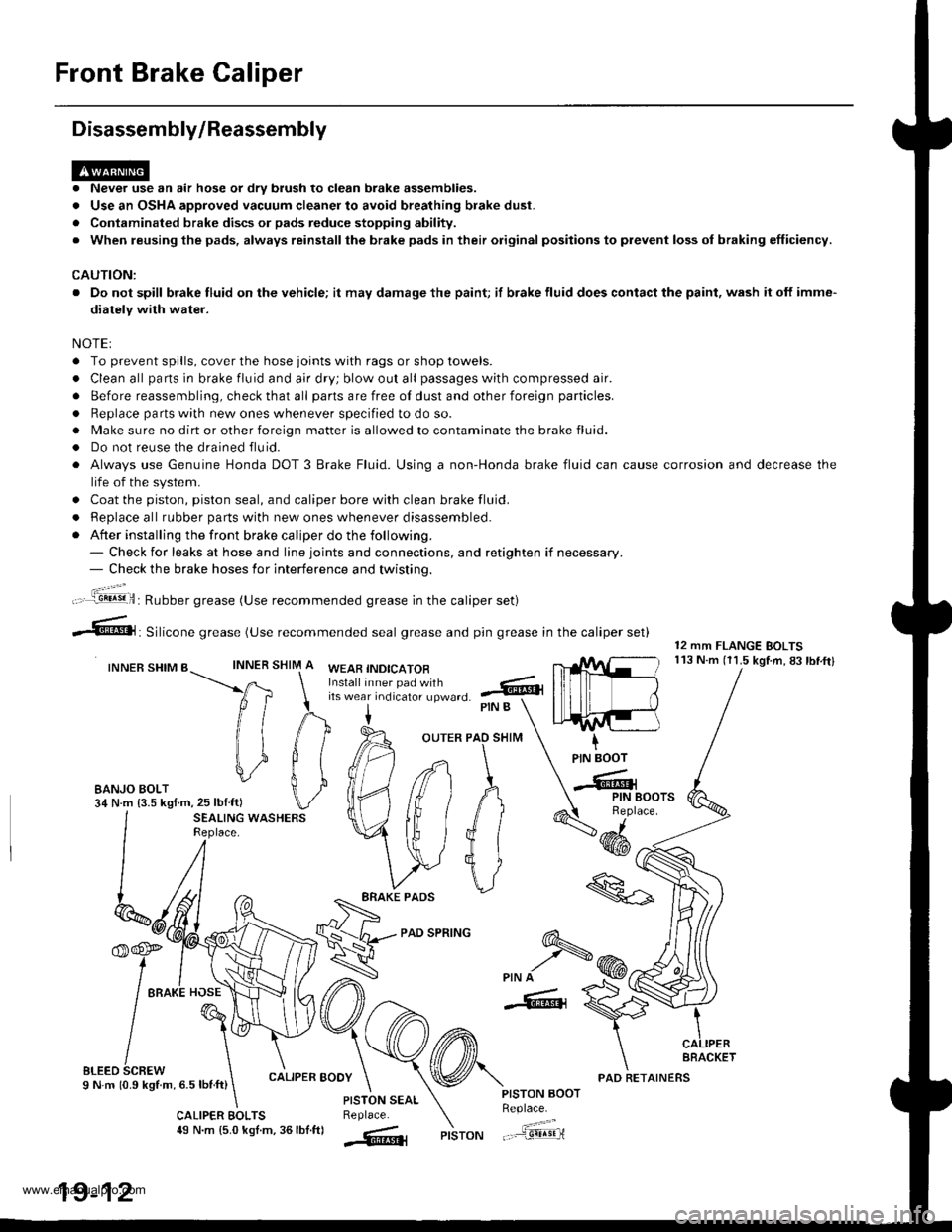
SHIM
12 mm FLANGE BOLTS113 N.m (11.5 kgtm,83lbf.ftlINNER
ft
il1
#
\i
#
PIN B
OUTER PAO SHIM
PAD SPRING
IPIN BOOT
-Cr
SEALING WASHERSReplace.4dd*
ERAKE PADS
'f,-rre
/ tto*l "o"\
t@I
/\'
sLreo 6cnew \I N m 10.9 kStm, 6.5 lbnft)
\
6-
>PIN A
-6, {
CALIPER BOOY
CALIPER EOLTS49 N.m {5.0 kgl.m, 36lbf.ftl
PISTON AOOTReplace.
"..-a=a-...,--"sEqriPISTON
t".:jil,,.'.1!!!!9!il: Rubber grease (Use recommended grease in the caliper set)
irf"i:;;T::fl,-J'I",0 .@
--6, Silicone grease (use recommended seal grease and p,n grease in the caliper set)
INNER SHIM BWEAB INDICATOR
EANJO BOLT34 N.m {3.5 kgf m,25 lblftl
PISTON SEALReplace.
AFACKET
19-12
PAD RETAINERS
www.emanualpro.com
Page 1020 of 1395
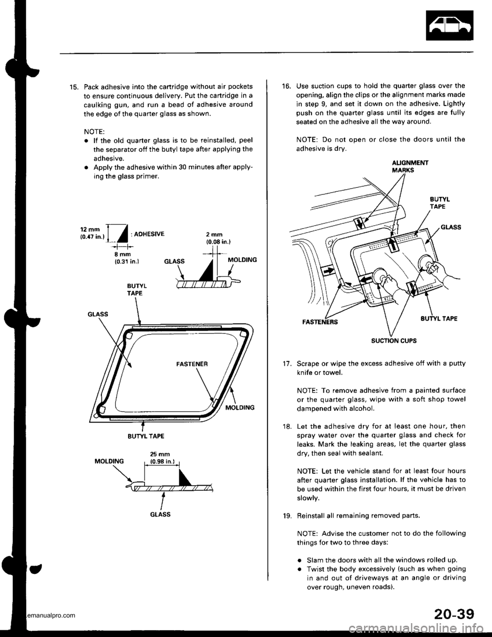
15. Pack adhesive into the cartridge without air pockets
to ensure continuous delivery, Put the canridge in a
caulking gun, and run a bead of adhesive around
the edge of the quarter glass as shown.
NOTE:
. lf the old quarter glass is to be reinstalled, peel
the separator off the butyl tape after applying the
adhesive.
. Apply the adhesive within 30 minutes after apply-
ing the glass primer.
i:.8T".,1,/:AoHEsrvE
I rnm(0.31 in.)
BUTYLTAPE
GLASS19.
20-39
16. Use suction cups to hold the quarter glass over the
opening, align the clips or the alignment marks made
in step 9, and set it down on the adhesive. Lightly
push on the quaner glass until its edges are fully
seated on the adhesive all the way around.
NOTE: Do not open or close the doors until the
adhesive is drv.
Scrape or wipe the excess adhesive off with a putty
knife or towel,
NOTE: To remove adhesive from a painted surface
or the quarter glass, wipe with a soft shop towel
dampened with alcohol.
Let the adhesive dry for at least one hour. then
spray water over the quarter glass and check for
leaks. Mark the leaking areas, let the quarter glass
dry, then seal with sealant.
NOTE: Let the vehicle stand for at least four hours
after quarter glass installation. lf the vehicle has to
be used within the first four hours, it must be driven
slowly.
Reinstall all remaining removed parts.
NOTE: Advise the customer not to do the following
things for two to three days:
. Slam the doors with all the windows rolled up.
. Twist the body excessively (such as when going
in and out of driveways at an angle or driving
over rough, uneven roads).
11.
18.
AUGNMENT
SUCTION CUPS
www.emanualpro.com
Page 1067 of 1395
Moldings
Door Moldings Replacement (cont'd)
It the old molding is to be reinstalled:
The following materials and tools are required to repair
the molding.
NOTE: Followthe manufacturer's instructions.
Materials: (Reference)
. Stripe remover
3M 08907
. Stripe adhesive remover
3M 08908
. Adhesive tape
3M Super Automotive Attachment Tape
Tools:
. Protective tape
. Knife or Cutter
. Sponge or Shop towel
. Infrared dryer
. Film
. Plastic putty knife
. Alcohol
CAUTION: Put on gloves to protect your hands,
1. lf necessary, replace any damaged clips on the mold-
ang.
2. Apply the stripe remover evenly to the bonding sur-
face of the body and molding.
3. Cover the bonding surface of the body and molding
with a film, then heat to 104 - 122"F (40 - 50'C) for 5- 10 minutes with an infrared dryer.
NOTE: Use care when heating to prevent deforma-
tion of the body and molding.
4. Carefully scrape the adhesive tape with a plastic
putty knife.
For removal of adhesive tape residue, follow-up with
stripe adhesive remover, then scrape the adhesive
tape with a plastic putty knife.
Remove the protective tape, then clean the bonding
surface with a sponge dampened in alcohol.
NOTE: Make sure the bonding surface is kept free or
water, oil and grease.
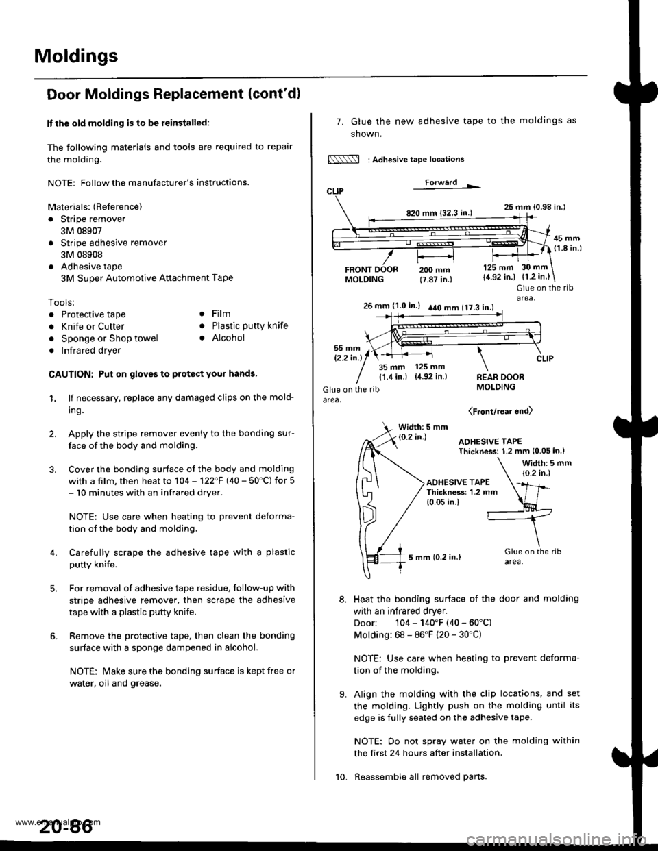
7. Glue the new adhesive tape
snown,
N : Adlesive tape locations
Forwerd L
820 mm 132.3 in.)
FRONTMOLDING
to the moldings as
25 mm {0.98 in.l
45 mm(1.8 in.l
200 mm(7.87 in.)
125 mm
{4.92 in.)30 mm
{1.2 in.}
t'.
Glue on the ribarea,26 mm (1.0 in.) 440 mm 117.3 in.l
35 mm 125 mm
{1.4 in.) {4.92 in.)REAR DOORMOLDING
(Front/rear end)
Width: 5 mm
Heat the bonding surface of the door and molding
with an infrared dryer.
Door: 104 - 140'F (40 - 60'C)
Molding: 68 - 86'F (20 - 30'C)
NOTE: Use care when heating to prevent deforma-
tion of the molding.
Align the molding with the clip locations, and set
the molding. Lightly push on the molding until its
edge is fully seated on the adhesive tape.
NOTE: Oo not spray water on the molding within
the first 24 hours after installation.
Reassemble all removed parts.10.
www.emanualpro.com
Page 1148 of 1395
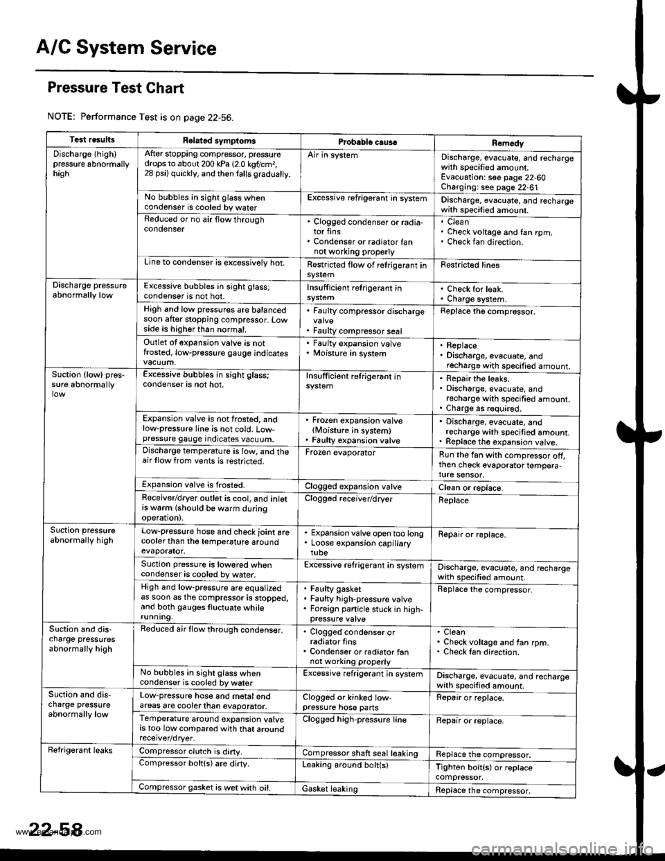
A/C System Service
Pressure Test Chart
NOTE: Performance Test is on page 22-56.
Test resultsRelatad symptomsPrcbable caus€Remody
Discharge (high)pressure 6bnormallyhagh
After stopping compressor, pressuredrops to about 200 kPa 12.0 kgtlcm,,28 psi) quickly, and then lalls gradualty.
Air in systemDischarge, evacuate, and rechargewith specified amount.Evacuation: see page 22-60Charging: see page 22-61No bubbles in sight glass whencondenser is cooled by waterExcessive refrigerant in systemDischarge, evacuate, and rechargewith specilied amount.Reduced or no air flow throughcondenser. Clogged condenser or radia-tor fins. Condenser or radiator fannot wo.king properly
CleanCheck voltage and fan rpm.Check fan direction.
Line to condensor is excossivelv hot.Restricted flow of relrigerant insy$emFestricted lines
Discharge pressureabnormally lowExcessive bubbles in sight glass;condenser is not hot.Insufficient retrigerant inCheck for leak.Charge system.High and low pressures are balancedsoon after stopping compressor. Lowside is higher than normal.
. Faulty compressor discharge
. Faulty compressor seal
Replace the comprossor.
Outlet ot expansion valve is notfrosted, low-pressure gauge indicates
' Faulty expansion valve. Moisture in system. Replace. Discharge, evacuate, andrecharge with specified amount.Suction {low) pros,sure abnormallyExcessive bubbles in sight glass;condenser is not hot.Insufficiont relrigerant inRepair the leaks.Discharge, evacuate, andrecharge with specified amount.Charge as r€quired.Expansion valve is not frosted, andlow-pressure line is not cold. Low-pressure gauge indicates vacuum.
' Frozen expansion valvelMoisture in system). Faulty expansion valve
. Discharge, evacuate, andrecharge with specitied amount.. Replace th€ expansion valve.Discharge temperature is low, and theair llow trom vents is restricted.Frozen evaporatorRun the fan with compressor off,then check evaporator tempera,ture sensor.Expansion valve is frosted.Clogged expansion valveClean or replace.Feceiver/dryer outlet is cool, and inlotrs w6rm (should be warm duringoperation).
Clogged receiver/dryerReplace
Suction pressureabnormally highLow-pressure hose and check joint arecooler than tho temperature aroundevaporator.
. Expansion valve open too long. Loose expansion capillarytube
Repair or roplace.
Suction pressure is lowored whencondenser is cooled by water.Excessive refrigerant in systemDischarge, evacuate, and rechargewath specified amount.High and low-pressure are equalizedas soon as tho compressor is stopped,and both gauges tluctuate whilerunning.
Faulty gasketFaulty high-pressure valveForeign panicle stuck in high-
Replace the compressor.
Slction and dis,charge pressutesabnormally high
Reduced air flow through condens€r,. Clogged condenser orradiator tins. Condenser or radiator fannot working properly
CleanCheck voltage and fan rpm.Check Ian direction.
No bubbles in sight glass whencondenser is cooled by walerExcessive refrigerant jn systemDischarge, evacuate, and rechargewith specified amount.Suction and dis-charge pressureabnormally low
Low-pressure hose and motalendareas are cooterlhan evaporator.Clogged or kinked low-pressure hose pansRepair or replace.
Temperature around expansion valvers too low compared with that aroundClogged high-pressure lineRepair or replace.
Refrigerant leaksCompressor clutch is diny.Compressor shaft seal leakingReplace the compressor.Compressor boltls) are dirty.Leaking around bolt(s)Tighton bolt{s) or replacecompressor.Compressor gasket is wet with oil.Gasket leakingReplace the compressor,
www.emanualpro.com
Page 1164 of 1395
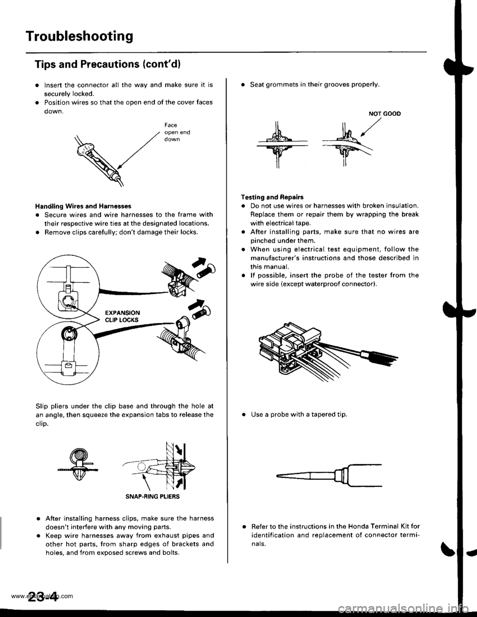
Troubleshooting
Tips and Precautions (cont'dl
Insen the connector all the way and make sure it is
securely Iocked.
Position wires so that the open end of the cover faces
down.
V
Faceopen end
Handling Wires and Harnesges
. Secure wires and wire harnesses to the frame with
their respective wire ties at the designated locations.
. Remove clips carefully; don't damage their locks.
Slip pliers under the clip base and through the hole at
an angle, then squeeze the expansion tabs to release the
clrD.
After installing harness clips, make sure the harness
doesn't interfere with any moving pans.
Keep wire harnesses away from exhaust pipes and
other hot parts, trom sharp edges of brackets and
holes. and from exoos€d screws and bolts.
NOT GOOD
A -M/
lr lr*
T€sting and Repairs
. Do not use wires or harnesses with broken insulation.
Replace them or repair them by wrapping the break
with electricaltape.
. After installing parts, make sure that no wires are
pinched under them.
. When using electrical test equipment, follow the
manufacturer's instructions and those described in
this manual.
. lf possible, insert the probe of the tester from the
wire side (except waterproof connector).
. Seat grommets in their grooves properly.
. Use a probe with a tapered tip.
Refer to the instructions in the Honda Terminal Kit for
identification and replacement of connector termi-
nals.
www.emanualpro.com
Page 1316 of 1395
Precautions/Procedures
)General Precautions
Carefully inspect any SRS part before you install it.
Do not install any part that shows signs of being drop-
ped or improperly handled, such as dents, cracks or
deformation:
- Airbags- Cable reel- SRS unit- Seat belt tensioners
N
)-
Use only a digital multimeter to check the system, lf
it's not a Honda multimeter, make sure its output is
10 mA (0,01 A) or less when switched to the smallest
value in the ohmmeter range. A tester with a higher
output could damage the airbag circuit or cause acci-
dental deployment and possible injury.
Do not install used SRS Dans from another vehicle,
When making SRS repairs, use only new pans.
Except when performing electrical inspections,
always disconnect both the negative cable and posi-
tive cable from the batterv. and wait at least three
minutes before beginning work.
Replacement of the combination light and wiper/
washer switches and cruise control switch can be
done without removing the steering wheel:
- Combination light and wiper/washer switch replace-
ment {see section 231.- Cruise control sevresume switch replacement (see
section 41.
Whenever the ignition switch is ON {ll}, or has been
turned OFF for less than three minutes, be careful not
to bump the SRS unit; the airbags could accidentally
deploy and cause damage or injuries.
Whenever the airbag has been activated, replace the
SRS unit.
The original radio has a coded theft protection circuit.
Be sure to get the customer's code number before dis-
connecting the battery cables.
)
Airbag/Seat Belt Tensioner
Handling and Storage
Do not try to disassemble an airbag or a seat belt ten-
sioner. They have no serviceable parts. Once an airbag
or a seat belt tensioner have been deployed. they cannot
be repaired or reused.
For temporary storage of an airbag or a seat belt ten-
sioner during service, please observe the following pre-
cautons:
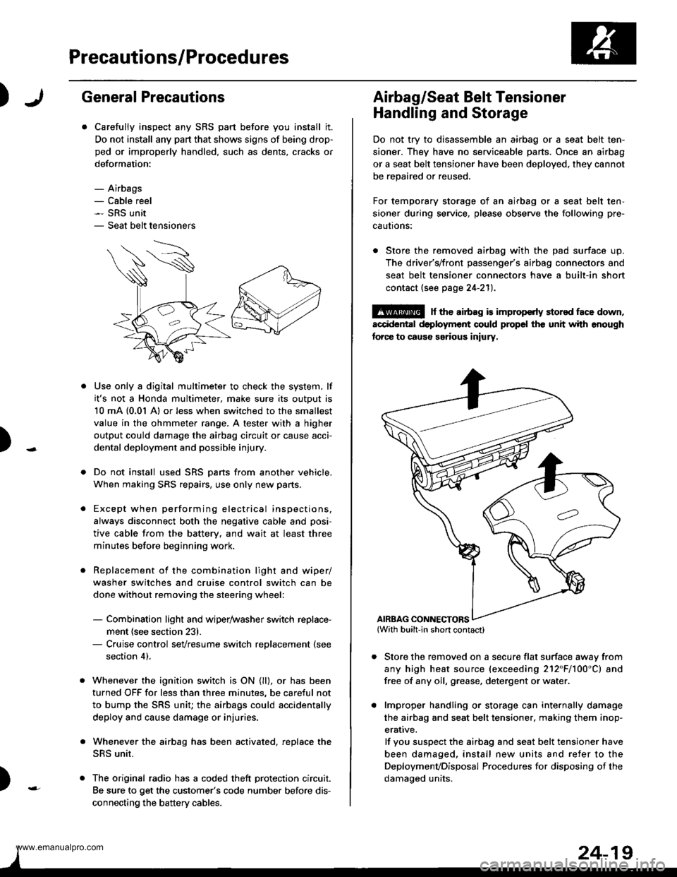
. Store the removed airbag with the pad surface up.
The driver's/front passenger's airbag connectors and
seat belt tensioner connectors have a built-in short
contact (see page 24-211.
@ r th€ airb.g is impropcrty stor€d face down,
accidental deployment could propel the unit with enough
forc€ to caus6 serious iniury,
Store the removed on a secure flat surface awav from
any high heat source (exceeding 212"F/100'C) and
free of any oil, grease. detergent or water.
lmproper handling or storage can internally damage
the airbag and seat belt tensioner. making them inop-
erative.
lf you suspect the airbag and seat belt tensioner have
been damaged, install new units and refer to the
Deploymenvoisposal Procedures for disposing of the
damaoed units.
AIRBAG CONNECTORS
www.emanualpro.com
Page 1317 of 1395
Precautions/Procedures
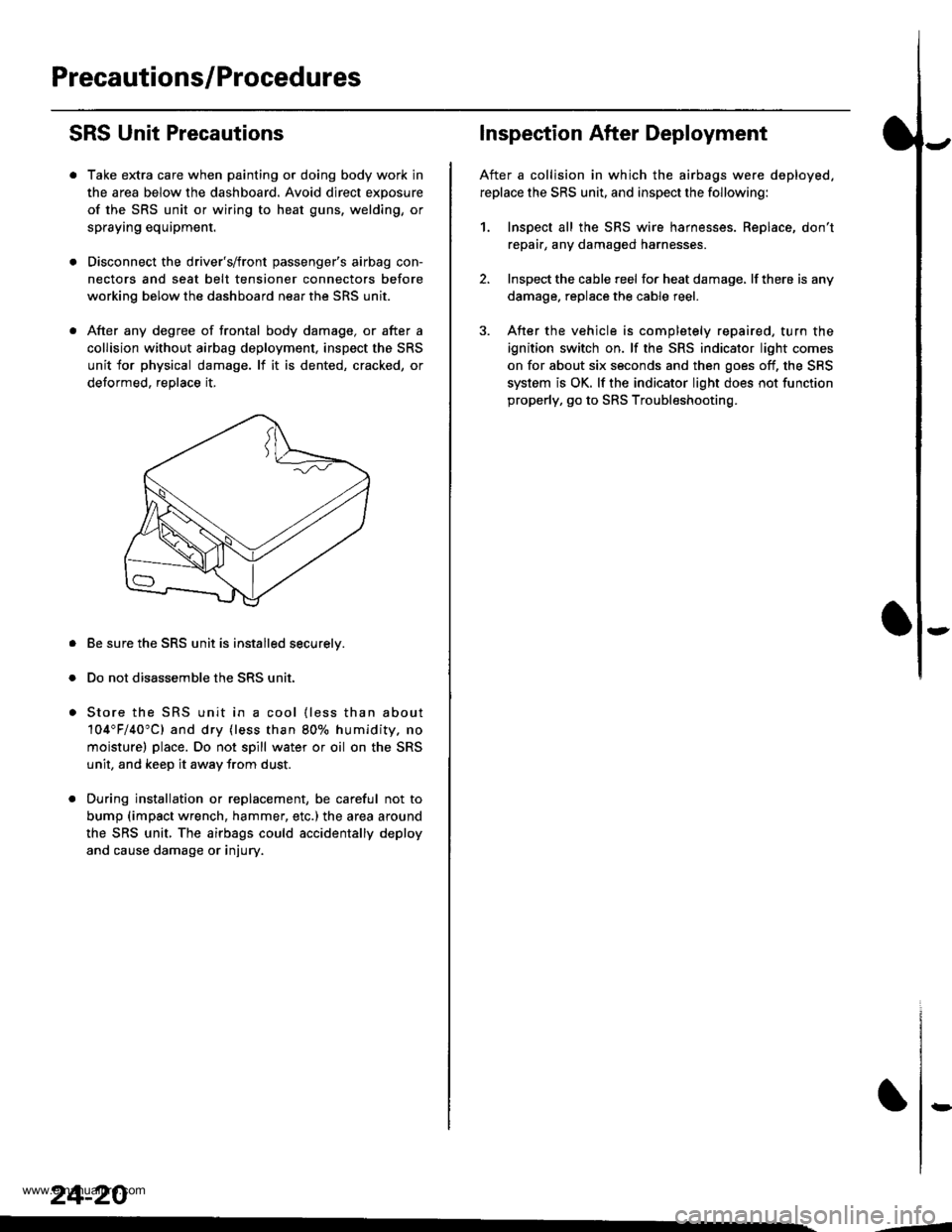
SRS Unit Precautions
Take extra care when painting or doing body work in
the area below the dashboard. Avoid direct exposure
of the SRS unit or wiring to heat guns, welding, or
spraying equipment.
Disconnect the driver's/front passenger's airbag con-
nectors and seat belt tensioner connectors before
working below the dashboard near the SRS unit.
After any degree of frontal body damage, or after a
collision without airbag deployment, inspect the SRS
unit for physical damage. lf it is dented, cracked, or
detormed, reolace it,
Be sure the SRS unit is installed securelv.
Do not disassemble the SRS unit.
Store the SRS unit in a cool {less than about
104"F/40"C) and dry {less than 80o/o humidity. no
moisture) place. Do not spill water or oil on the SRS
unit, and keep it awav from dust.
During installation or replacement, be careful not to
bump (impact wrench, hammer, etc.) the area a[ound
the SRS unit, The airbags could accidentally deploy
and cause damage or injury.
24-20
,..4
Inspection After Deployment
After a collision in which the airbags were deployed.
replace the SRS unit, and inspect the following:
1. Inspect all the SRS wire harnesses. Replace, don't
repair, any damaged harnesses
2. Inspect the cable reel for heat damage, lf there is any
damage. replace the cable reel.
3. After the vehicle is completely repaired, turn the
ignition switch on. lf the SRS indicator light comes
on for about six seconds and then goes off, the SRS
system is OK. lf the indicator light does not function
properly, go to SRS Troubleshooting.
rD
www.emanualpro.com
Page 1392 of 1395
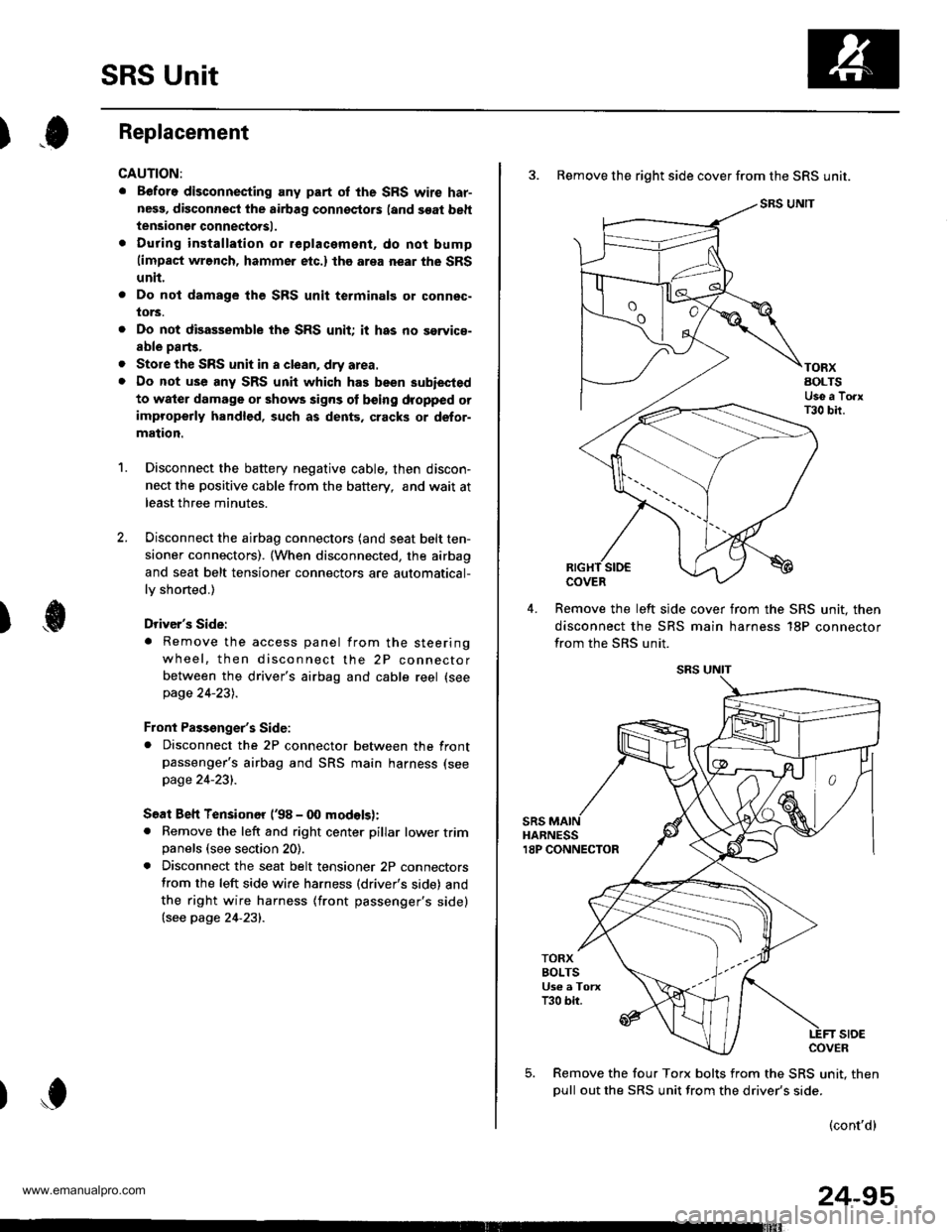
SRS Unit
).0Replacement
CAUTION:
. Before disconnecting any part of the SRS wire har-
nesg, disconnect the airbag connoctors (and soat beh
tensioner connectorsl.
. During installation or replacament, do not bump(impact wrench, hammer etc.) the area near the SRS
unit.
Do not damage the SFS unit terminalg or connsc-
lors.
Do not disassemble the SRS unit it has no saryice-
able parts,
Store the SRS unit in a clean, dry area.
Do not use any SRS unit which has been subiected
to water damage or shows signs ot being dropped orimproperly handlgd, such as dents, cracks or defor-
mation.
Disconnect the battery negative cable, then discon-
nect the positive cable from the battery, andwaitat
least three minutes.
Disconnect the airbag connectors (and seat belt ten-
sioner connectors). (When disconnected, the airbag
and seat belt tensioner connectors are automatical-
ly shorted.)
Driver's Side:
. Remove the access panel from the steering
wheel, then disconnect the 2P connector
between the driver's airbag and cable reel (see
page 24-231.
Front Passenger's Side:. Disconnect the 2P connector between the frontpassenger's airbag and SRS main harness (see
page 24-231.
Soat Beh Tensionor ('98 - 00 modelsr:. Remove the left and right center pillar lower trimpanels (see section 20).
. Disconnect the seat belt tensioner 2P connectors
from the left side wire harness (driver's side) and
the right wire harness (front passenger's side)(see page 24'231.
2.
a
a
'1.
)
)o
24-95
3. Remove the right side cover from the SRS unit.
SRS UNIT
TORXAOLTSUse a TorxT30 bir.
COVER
Remove the left slde cover from the SRS unit. then
disconnect the SRS main harness 18P connector
from the SRS unit.
sRsHARNESS18P CONNECTOR
TORXBOLTSUs€ a TorxT30 bir.
stoECOVER
Remove the four Torx bolts from the SRS unit. then
oull out the SRS unit from the driver's side.
(cont'd)
www.emanualpro.com
Page 1395 of 1395
Airbag/Seat Belt Tensioner
1.
Disposal (cont'dl
Connect a 12 volt battery to the tool'
. It the green light on the tool comes on, the air-
bag igniter circuit is defective and cannot deploy
the airbag. Go to Damaged Airbag Special
Procedure.
.lftheredlightonthetool comes on, the airbag is
ready to be deployed.
Push the tool's deployment switch. The airbag
should deploy (deployment is both highly audible
and visible; a loud noise and rapid inflation of the
bag, followed by slow deflation).
. lf the airbags deploy and the green light on the
tool comes on, continue with this procedure.
. lf an airbag doesn't deploy, yet the green light
comes ON, its igniter is defective. Go to Dam-
aged Airbag Special Procedure.
. During deployment, the airbag can become hot
enough to burn you, Wait thirty minutes after
deployment before touching the airbag.
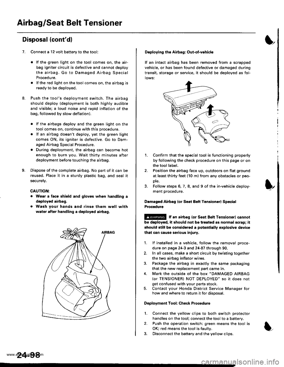
Dispose of the complete airbag. No part of it can be
reused. Place it in a sturdy plastic bag, and seal it
securety.
CAUTION:
. Wear a faco shield and gloves when handling a
deployed airbag.
. Wash your hands and rinse them well with
water after handling a deployed airbag.
24-98
Deploying tho Airbag: Out-ot.vohicle
lf an intact airbag has been removed from a scrapped
vehicle, or has been found defective or damagsd during
transit. storage or seryice, it should be deployed as fol-
lows:
'L Confirm that the special tool is functioning properly
by following the check procedure on this page or on
the tool label.
2. Position the airbag face up, outdoors on flat ground
at least thirty feet (10 m) from any obstacles or peo-
Dte,
3. Follow steps 6, 7, 8. and 9 of the in-vehicle deploy-
ment proceoure.
Dlmaged Airbsg {or Seat Beh Ten3ion6r} Sp6cial
Procgdure
!@ r an airbag {or seat Beh rensioner} cannol
be doployod, it should not be treated as normal scrap; it
should still be considered a pot€ntially explosive device
lhat can cause serious iniury.
1. lf installed in a vehicle. follow the removal proce-
dure on page 24-3 and 24-87 through 90.
2. In all cases, make a short circuit by twisting together
the two airbag inflator wires.
3. Package the airbag in exactly the same packaging
that the new reDlacement Dart came in.
4. Mark the outside of the box "DAMAGED AIRBAG
{or TENSIONER) NOT DEPLOYED" so it does not
get confused with your parts stock.5. Contact your Honda District Service Manager forhow and where to return it for disposal.
Deployment Tool: Check Procedure
Connect the yellow clips to both switch protector
handles on the tool; connect the tool to a battery.
Push the operation switch: green means the tool is
OK: red means the tool is faultv.
Disconnect the baftery and the yellow clips.
I
t
l.
www.emanualpro.com