abs HONDA CR-V 2000 RD1-RD3 / 1.G User Guide
[x] Cancel search | Manufacturer: HONDA, Model Year: 2000, Model line: CR-V, Model: HONDA CR-V 2000 RD1-RD3 / 1.GPages: 1395, PDF Size: 35.62 MB
Page 267 of 1395
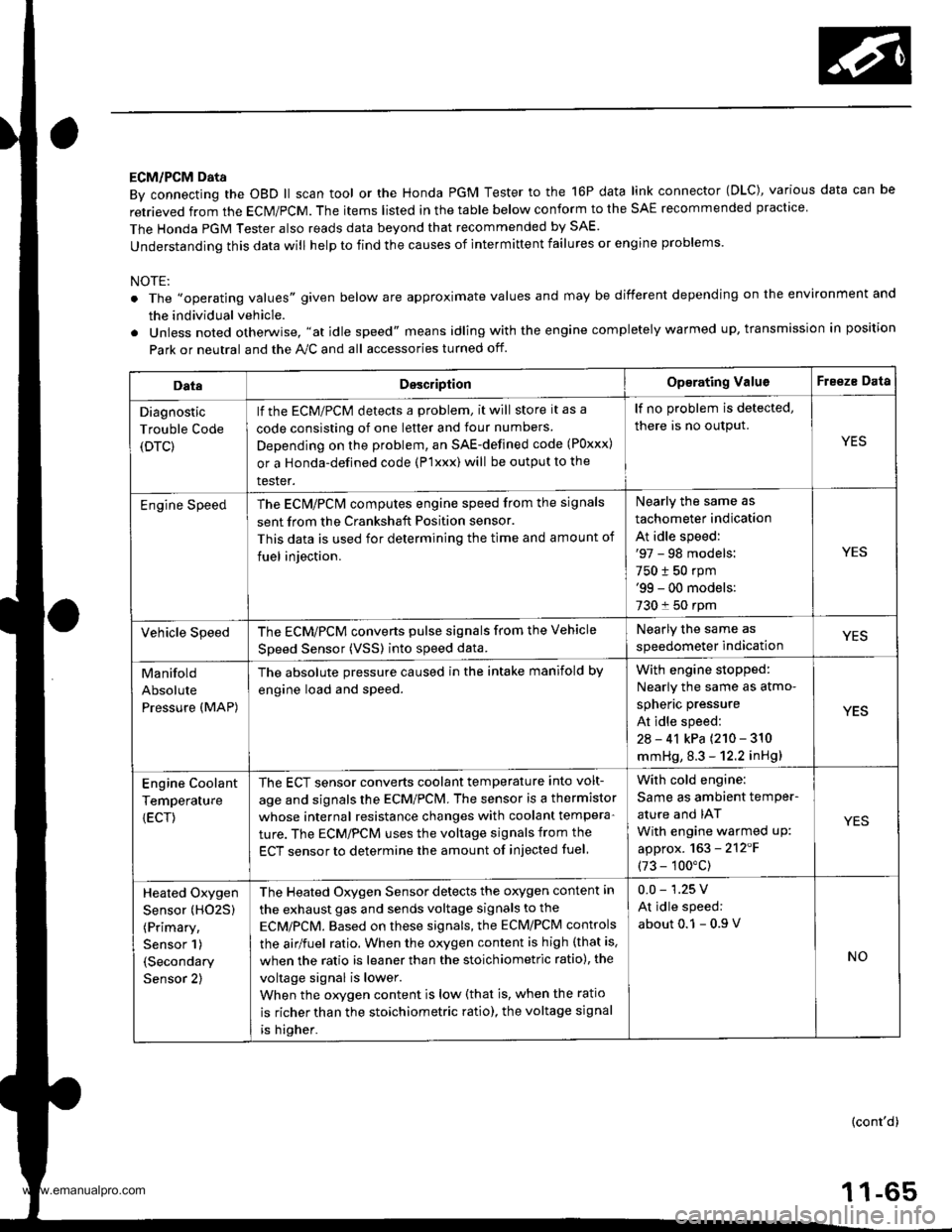
ECM/PCM Data
By connecting the OBD ll scan tool or the Honda PGM Tester to the 16P data link connector (OLC), various data can be
retrieved from the ECM/PCM. The items listed in the table below conform to the SAE recommended practice
The Honda PGM Tester also reads data beyond that recommended by SAE.
understanding this data will help to find the causes of intermittent failures or engine problems.
NOTE:
The ',operating values" given below are approximate values and may be different depending on the environment and
the individual vehicle.
Unless noted otherwise. "at idle speed" means idling with the engine completely warmed up, transmission in position
Park or neutral and the A,./C and all accessories turned otf.
DataDesc.iptionOp€rating ValuoFreeze Data
Diagnostic
Trouble Code
(DTC)
lf the ECM/PCM detects a problem, it will store it as a
code consisting of one letter and tour numbers
Depending on the problem, an SAE-defined code (Poxxx)
or a Honda-defined code (P'lxxx) will be output to the
tester.
lf no problem is detected,
there is no output.
YES
Engine SpeedThe ECN4/PCN4 computes engine speed from the signals
sent from the Crankshaft Position sensor.
This data is used for determining the time and amount of
fuel iniection.
Nearly the same as
tachometer indication
At idle speed:'97 - 98 models:
750 t 50 rpm'99 - 00 models:
730 f 50 rpm
YES
Vehicle SpeedThe ECM/PCM converts pulse signals from the Vehicle
Speed Sensor (VSSI into speed data.
Nearly the same as
speedometer indicationYES
Manifold
Absolute
Pressure (MAP)
The absolute pressure caused in the intake manifold by
engine load and speed.
With engin6 stopped:
Nearly the same as atmo-
spheric pressure
At idle speed:
2a - 41 kPa {210 - 310
mmHg, 8.3 - 12.2 inHg)
YES
Engine Coolant
Temperature
{ECT)
The ECT sensor converts coolant temperature into volt-
age and signals the ECM/PCM. The sensor is a thermistor
whose internal resistance changes with coolant tempera-
ture. The ECM/PCM uses the voltage signals from the
ECT sensor to determine the amount of injected fuel
With cold engine:
Same as ambient temPer-
ature and IAT
With engine warmed uP:
approx. 163 - 2'12'F
(73 - 100"c)
YES
Heated Oxygen
Sensor (HO25)
(Primary,
Sensor 1)
(Secondary
Sensor 2)
The Heated Oxygen Sensor detects the oxygen content in
the exhaust gas and sends voltage signals to the
ECMiPCM. Based on these signals, the ECM/PCM controls
the airlfuel ratio. When the oxygen content is high (that is.
when the ratio is leaner than the stoichiometric ratio), the
voltage signal is lower.
When the orygen content is low (that is, when the ratio
is richer than the stoichiometric ratio), the voltage signal
is higher.
0.0 - 1.25 V
At idle speed:
about 0.1 - 0.9
NO
(cont'd)
1 1-65
www.emanualpro.com
Page 272 of 1395
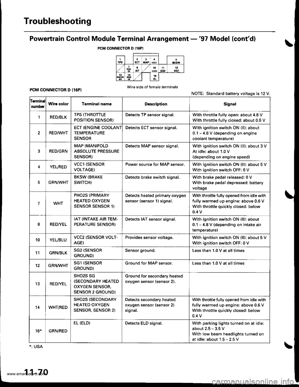
Troubleshooting
Powertrain Gontrol Module Terminal Arrangement -'97 Model (cont'd)
PCM CONNECTOR O {16PI
PCM CONNECTOR D (I6P)Wire side of f6male terminals
NOTE: Standard battery voltage is 12 V.
f.rminal
numbcrWir! colorT€rminal nam6DescriptionSignal
1RED/BLKTPS ffHROTTLE
POSITION SENSOR}
Detects TP sensor signal.With throttle fullv oDen: about 4.8 V
With throttle fullv closed: about 0.5 V
RE D,4/VHT
ECT (ENGINE COOLANT
TEMPERATURE
SENSOR
Detects ECT sensor signal.With ignition switch ON {ll): about
0.1 - 4.8 V (depending on engine
coolant temperature)
RED/GRN
MAP (MANIFOLD
ABSOLUTE PRESSURE
SENSOR)
Detects MAP sensor signal.With ignition switch ON (ll): about 3 V
At idle; about 1.0 V(depending on engine speed)
YEUREDVCCl (SENSOR
VOLTAGE)
Pow€r source for MAP sensor.With ignition switch ON (ll): about 5 V
With ignition switch OFF: 0 V
EG R N/WHT
BKSW (BRAKE
SWITCH)
Detects brake switch signal.With brake pedal released:0 V
With brake pedal depressed: battery
voltage
7WHT
PHO2S (PRIMARY
HEATED OXYGEN
SENSOR SENSOR 1)
Detects heated primary oxygen
sensor (sensor 1) signal.
With throttle fully opened from idle with
fully warmed up engine: above 0.6 V
With throttle quickly closed: below
0.4 v
8RED//E L
IAT (INTAKE AIR TEM.
PERATURE SENSOR)
Detects IAT sensor signal.With ignition switch ON lll): about
0.1 - 4.8 V (depending on intake air
temperaturel
10YEUBLUVCC2 (SENSOR VOLT-
AGEI
Provides sensor voltage.With ignition switch ON (ll): about 5 V
With ignition switch OFF: 0 V
11GRN/BLKSG2 (SENSOR
GROUND)
Sensor ground.Less than 1.0 V at all times
12GRN/WHTSGl (SENSOR
GROUND)
Ground for MAP sensor.Less than 1.0 V at all times
13RED/YE L
SHO2S SG(SECONDARY HEATED
OXYGEN SENSOR,
SENSOR 2 GROUND)
Ground for secondary heated
orygen sensor (sensor 2).
14WHT/RED
SHO2S (SECONDARY
HEATED OXYGEN
SENSOR, SENSOR 2)
Detects secondary heated
orygen sensor (sensor 2)
signal,
With throttle fully opened from idle with
fully warmed up engine; above 0.6 V
With throttle quickly closed: below
0.4 v
16*GRN/RED
EL (ELD)Detects ELD signal.With parking lights turned on at idle
about 2.5 - 3.5 V
With low beam headlights turned on
at idle: about 1.5 - 2.5V
1-70
www.emanualpro.com
Page 275 of 1395
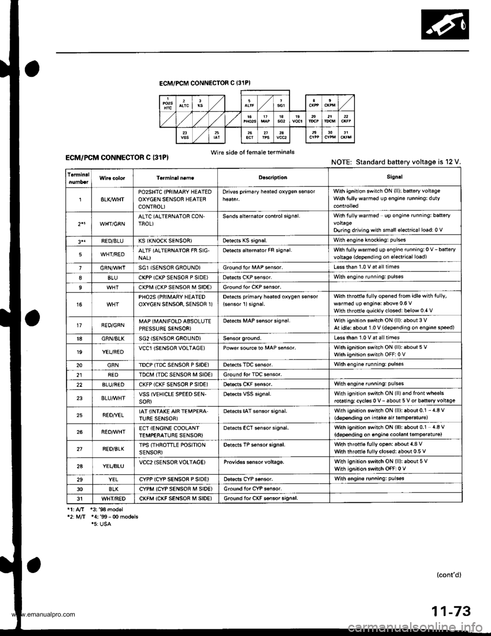
ECM/PCM CONNECTOF C (31PI
Wire side o{ female terminal€ECM/PCM CONNECTOR C (31P)NOTE: Standard battery voltage is 12 V.
TermidalD.3criptionSignal
8LI(WHTPOzSHTC {PRIII4ABY HEATEDOXYGEN SENSOR HEATERCONTROL)
Drivss prim6ry h$ted oxygsn sensorWilh ignition switch ON (ll): baneryvoltsgeWith ftrllywarmsd up €ngine runnang: duty
2"WHT/GBNALTC (ALTERNATOR CON,TROL)Sonds alternalor control signsl.With fully wafmod up €ngine rnningr ban€ryvoltagoDu ng driving with small elsctrical lo6d: 0 v
3'1FED/8LUKS (KNOCK SENSOR)Dstects KS signal.With engine knockang: pulses
5WHT/REDALTF (ALTERNATOR FR SIG-NAL}Detects alternator FR signal.Wth fullywarmed up €ngine running:0 V-batteryvoltag€ {d€pending on slsctrical load)
1GRN,4trHTSG1 (SENSOR 680UND}Ground for l/tAP sensor.L€ss than 1.0 v 6t all times
8BLUCKPP (CKP SENSOF P SIDE)Dat€cls CKP s6nsor.With €ngin€ runningr puls€s
9CKPI.,I| {CKP SENSOF M SIDE)Ground for CKP s€nsor.
15PHO2S {PRIMARY HEATEDOXYGEN SENSOR, SENSOR 1)Detocts pfimary he6t6d oxygen ssnsor
{sonsor 1)signal.with ihfottls fully opened from idle with fully,
walm6d up engins: above 0.6 VWith throttlo quickly clossd: below 0.4 v
17RED/GRNMAP (MANIFOLD ABSOLUTEPRESSURE SENSOR)
D6tects MAP s€nsor sign6l.With ignition switch ON (ll):about 3 VAt idls: aboul 1.0 V {dspsnding on engine speed)
18GRN/BLKSG2 (SENSOB GNOUNDiLsss than 1.0 V at all tim€s
19YEUBEDVCCl {SENSOR VOLTAGE)Power soufce to MAP s€nsor.With ignition switch ON (ll): about 5 VWith ignition switch OFF:0 V
20GRNTDCP {TDC SENSOR P SIDE)Derecis TDC sensor.With engine funning: Pulses
2lREDTDCM ITDC SENSOR M SID€)Ground for TDC sensor.
22BLU/REDCKFP (CKF SENSOR PSIDE)Dstscts CKF s€nsor.With sngins running: pulsss
23BLU/WHTVSS (VEHICLE SPEED SEN-soR)Dstscrs vss signal.With ignition switch ON (ll)and front wheelsrotaringrcyclss 0 v- 6bout 5 V or ban€ry voltage
25RED//ELIAT (INTAKE AIR TEMPERA'TURE SENSOB)Detacts IAT sensor signal.With igniiion switch ON (ll): about 0.1 - 4.8 V(d€p€nding on iniate air t€mp€raturc)
26REO/WHTECT {ENCINE COOLANTTEMPERATURE SENSOR)oetscts ECT sensor signal.With ignition switch ON (ll): about 0.1 4.8 V
{doponding on 6ngin€ coolanl lemper6tu16)
27RED/BLKTPS (THROTTLE POSITIONSENSOR)Dotects TP sensor signrl.with rhrottls fully op€n: aboui 4.8 vwith throtrl6 fullyclosed: about 0.5 v
2AYEUBLUVCC2lSENSOR VOLTAG€}Provid€s s€nsor voltage.With ignilion switch ON (ll): about 5 VWhh ignition switch OFF: 0 V
29YELCYPP ICYP SENSO8 P SIDE)Dsrscts CYP sensor.With €ngins runningr pulsss
30BLKCYPM (CYP SENSOR M SIDE)Ground for CYP sansor.
31WHT/REDCKFM {CKF SENSOR M SIDE)6.ound lof CKF ssnsor signal.
11. AfT 13. '94 model'2:M/T 14:'99- 0o modsls.5: USA
(cont'd)
11-73
www.emanualpro.com
Page 277 of 1395
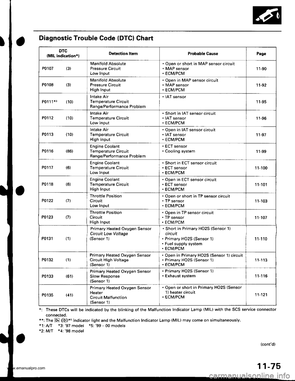
Diagnostic Trouble Code (DTCI Chart
*: These DTCS will be indicated by the blinking of the Malfunction Indicator Lamp (MlL) with the SCS service connector
connected.**: The E (E)*u indicator tight and the Malfunction Indicator Lamp (MlL) may come on simultaneously.*1' AIT *3 '97 model +5; '99 - 00 models*2: MlT *4:'98 model
{cont'd)
11-75
DTC(MlL indication*lDetection ltemProbable CausePago
P0107 (3)Manifold Absolute
Pressu.e CircuitLow Input
Open or short in MAP sensor circuit
MAP sensor
ECMiPCM
't 'l-90
P0108 {3)
Manifold AbsolutePressure Circuit
High Input
Open in MAP sensor circuitMAP sensor
ECM/PCM
11-92
P01 1 1*3 (10)Intake Air
Temperature Circuit
Range/Performance Problem
. IAT sensor
11-95
P0112 (10)lntake Air
Temperature CircuitLow Input
Short in IAT sensor circuit
IAT sensorECM/PCM1 1-96
P0113 (10)lntake Air
Temperature Circuit
High lnput
Open in IAT sensor circuit
IAT sensor
ECM/PCM
'I 1-97
P0116 (86)Engine CoolantTemperature CircuitRange/Performance Problem
ECT sensor
Cooling system1 1-99
P0117 (6)Engine Coolant
Temperature Circuit
Low Input
Short in ECT sensor circuit
ECT sensor
ECM/PCM
1 1-100
P0118 (6)Engine Coolant
Temperature CircuitHigh Input
Open in ECT sensor circujt
ECT sensor
ECM/PCM
11-101
P0122 \11
Throttle Position
Circuit
Low Input
Open or short in TP sensor circuitTP sensor
ECM/PCM
11-103
P0123 l7l
Throftle Position
Circuit
High Input
Open in TP sensor circuit
TP sensor
ECM/PCM11-107
P0131 (1)
Primary Heated Oxygen Sensor
Circuit Low Voltage(Sensor 1)
Short in Primary HO2S {Sensor 1)
circuit
Primary HO2S (Sensor 1)
Fuel supply system
ECM/PCM
1 1-1 10
P0132 (1)Primary Heated Orygen SensorCircuit High Voltage(Sensor 1)
Open in Primary HO2S (Sensor 1) circuitPrimary HO25 (Sensor 1)ECM/PCM
'11113
P0133 (61)Primary Heated Oxygen Sensor
Slow Response(Sensor 1)
. Primary HO2S (Sensor 1). Exhaust system11'I 16
P0135 (41)
Primary Heated Oxygen SensorHeater
Circuit Malfunction
{Sensor 1)
. Open or short in Primary HO2S (Sensor'l) heater circuit. ECM/PCM11-12'l
www.emanualpro.com
Page 279 of 1395
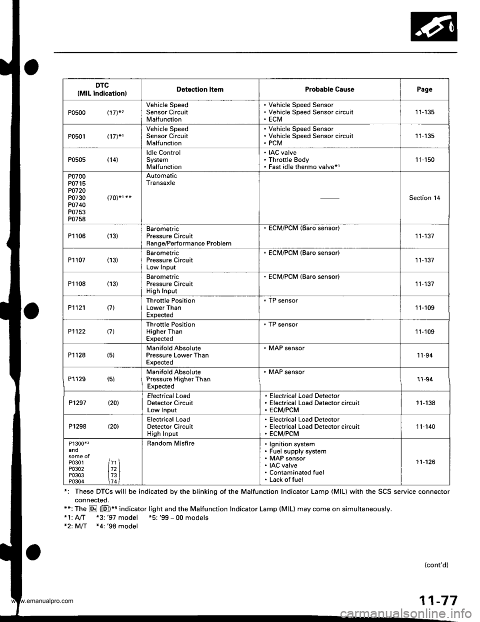
DTC(MlL indicationlDotection ltomProbable CausePage
P0500 t17)*,
Vehicle SpeedSensor CircuitMalfunction
Vehicle Speed SensorVehicle Speed Sensor circu itECtVI1 1-135
P0501 l17J*1
Vehicle SpeedSensor CircuitMalfunction
Vehicle Speed SensorVehicle Speed Sensor circuitPCM11-135
P0505 (14)ldle ControlSystemMalfunction
IAC valveThrottle BodyFast idle thermo valve*11 '�]- 150
P0700P0715PO720P0730P0740P0753P0758
AutomaticTransaxle
Section l4
P1106 (13)BarometricPressure CircuitRange/Performance Problem
ECM/PCM (Baro sensor)
11-137
P1107 (13)BarometricPressure CircuitLow InPut
. ECM/PCM {Baro sensor)11-137
P1108 (13)BarometricPressure CircuitHigh Inpur
ECM/PCM {Baro sensor)11,137
P1121 (7)Throttle PositionLower ThanExpected
. TP sensor11-109
P1122 (7)Throttle PositionHigher ThanExpected
' TP sensor1 1-'109
P112a (5)Manifold AbsolutePressure Lower ThanExpected
. MAP sensor11-94
P1129 (5)Manifold AbsolutePressure HiqherThanExpected
' MAP sensor1l-94
P1297 (20)Electrical LoadDetector CircuitLow Input
Electrical Load DetectorElectrical Load Detector circuitECM/PCM1 1- 138
P1298 (20)Electrical LoadDetector CircuitHigh Input
Electrical Load DetectorElectrical Load Detector circuitECM/PCM11-140
P1300'3
P0301P0302P0303P0304
7l721314
Random lvlisfirelgnition systemFuel supply systemMAP sensorIAC valveContaminated fuelLack offuel
11-126
*: These DTCS will be indicated by the blinking of the Malfunction Indicator Lamp {MlL} with the SCS service connector
connected.**:The E (E])+s indicator light and the Malfunction Indicator Lamp (MlL) may come on simultaneously.*1:A,./T "3: '97 model +5: '99 - 00 models*2: M/T *4:'98 model
{cont'd)
11-77
www.emanualpro.com
Page 292 of 1395
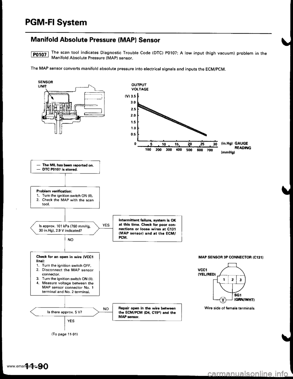
PGM-FI System
Manifold Absolute Pressure (MAPI Sensor
The scan tool indicates Diagnostic Trouble Code (DTC) POl07: A low input (high vacuum) problem in theManifold Absolute Pressure (MAP) sensor,
The MAP sensor convens manifold absolute pressure into electrical signals and inputs the ECM/pCM.
OUTPUIVOLTAGE
tvl3.s
3.0
2.5
2.O
1.5
1.0
0.5
o .5 ro- 15^ 1olin.H9) GAUGEREADIT{G
lmmHgl
3025
100 200 300 a00 5oo 6fi, 7d)
MAP SENSOR 3P CONNECTOR IC131I
vccl(YEL/RED}
Th6 MIL has b€en reoorted on.DTC P0107 is 3tored.
Problom verification:1. Turn the ignition switch ON lll).2. Check the lvlAP with the scanroot.
lrtormittem tailu.e, lystam b OKat thb timo. Check tor poor con-noctions or loosa wird at C131(MAP rensor) and rt the ECM/PCM.
ls approx. 101 kPa (760 mmHg,30 in.Hg),2.9 V indicated?
Check for an op6n in wi.o IVCC1linel:1. Turn the ignition switch OFF.2. Disconnect the MAP sensorconnector,3. Turn the ignition switch ON {ll}.4. Measure voltage between theMAP sensor connector No. 1termanal and No. 2 terminal.
Roprir op€n in the wir6 bstweentho ECM/PCM (D4, C19*l and theMAP sensor.
ls there approx. 5 V?
(To page 11-91)
11-90
Wiro side ol temale terminals
www.emanualpro.com
Page 294 of 1395
![HONDA CR-V 2000 RD1-RD3 / 1.G User Guide
PGM-FI System
Manifold Absolute Pressure (MAP) Sensor (contd)
[tn,t nn-] The scan tool indicates Diagnostic Trouble Code (DTC) P0108: A high voltage (low vacuum) problem in the|jg Manifold Absolute HONDA CR-V 2000 RD1-RD3 / 1.G User Guide
PGM-FI System
Manifold Absolute Pressure (MAP) Sensor (contd)
[tn,t nn-] The scan tool indicates Diagnostic Trouble Code (DTC) P0108: A high voltage (low vacuum) problem in the|jg Manifold Absolute](/img/13/5778/w960_5778-293.png)
PGM-FI System
Manifold Absolute Pressure (MAP) Sensor (cont'd)
[tn,t nn-] The scan tool indicates Diagnostic Trouble Code (DTC) P0108: A high voltage (low vacuum) problem in the|jg Manifold Absolute Pressure (MAP) sensor.
MAP SENSOR 3P CONNECTOR IC131I
Wire side of female terminals
vcclIYEL/RED}
PCM CONNECTOR D I16PI
JUMPER WIRE
sGlIGRN/WHTI
Wire side of lemale termin6ls
1
(To page 11,93)': '98 - 00 models
1-92
tcRN/wHrll IIRED/GRN|
The MIL has boen reported on.DTC m108 is slored.
Problem veritication:1. Start the engine. Hold theengine at 3,000 rpm with noload (in Park or neutral) untilthe radiator fan comes on, thenlet it idle.2. Check the MAP with the scantool.
Intermittent tailuro, system i3 OKat this time. Check tor ooor con-nections or loose wires at C131IMAP s6nsor) snd the ECM/rcM.
ls 101 kPa {760 mmHg,30 in.Hg),2.9 V or higher indicated?
Check Ior an open in the MAPsensor:1. Turn the ignition switch OFF.2. Disconnect the MAP sensor3P connector.3. lnstall a jumper wire betweenthe MAP sensor 3P connectorterminals No.3 and No.2.4. Turn the ignition switch ON {ll).5. Check the MAP with the scantool.
ls 10'l kPa (760 mmHg,30 in.Hg),2.9 V or higher indicated?
Check for an open in wire (SGlliDel:1. Remove the jumper wire.2. Measure voltage between theMAP sensor 3P connector ter-minals No. 1 and No- 2.
R6p.ir open in the wire betwoenthe ECM/PCM (D12, CTrl and theMAP sensor.
ls there approx. 5 V?
Check for an open in the wire(MAP line):1. Turn the ignition switch OFF.2. lnstall a iumper wire on thePCM connectors between D3and D12.3. Turn the ignition switch ON (ll).4. Check the MAP wirh the scantool.
Ropair opon in the wire betweenthe PCM {D3, .nd the MAP son-3('t.
ls 101 kPa 1760 mmHg, 30 in.Hg),2.9 V or higher indicated?
YES
www.emanualpro.com
Page 296 of 1395
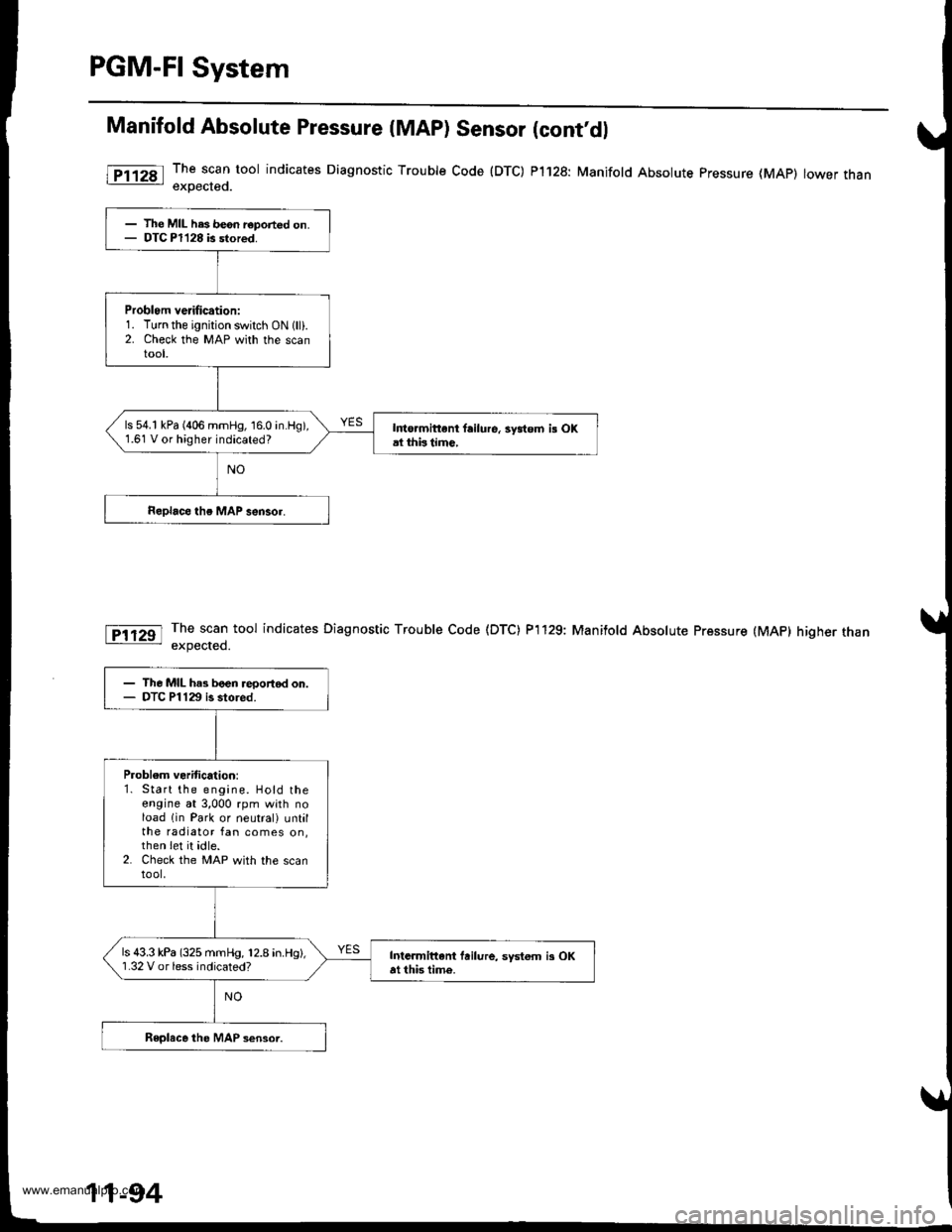
PGM-FI System
Manifold Absolute Pressure (MAP) Sensor (cont'dl
The scan tool indicates Diagnostic Trouble Code (DTC) P1128: Manifold Absolute pressure (MAp) lower thanexoected.
The scan tool indicates Diagnostic Trouble Code (DTC) P'l129: Manifold Absolute Pressure (MAP) higher thanexpected.
l
- The MIL has be6n r€ported on.- DTC Pl128 is stored.
Problom verification:1. Turn the ignition switch ON 1lli.2. Check the MAP with the scantool,
ls 54.1 kPa (406 mmHg, 16.0 in.Hg),1.61 V or higher indicated?I to.mittent failure, 3ydom i! OKal thbtimc,
- The MIL has boen reportod on.- DTC Pl129 is stored.
Problem veritication:1. Start the engine. Hold theengine at 3,000 rpm with noload lin Park or neutral) untilthe radiator fan comes on,then Iet it idle.2. Check the MAP with the scantool,
ls 43.3 kPa (325 mmHg, 12.8 in.Hg),'1.32 V or less indicated?Intarmittani fuilure, systom i3 OKat this time.
11-94
www.emanualpro.com
Page 377 of 1395
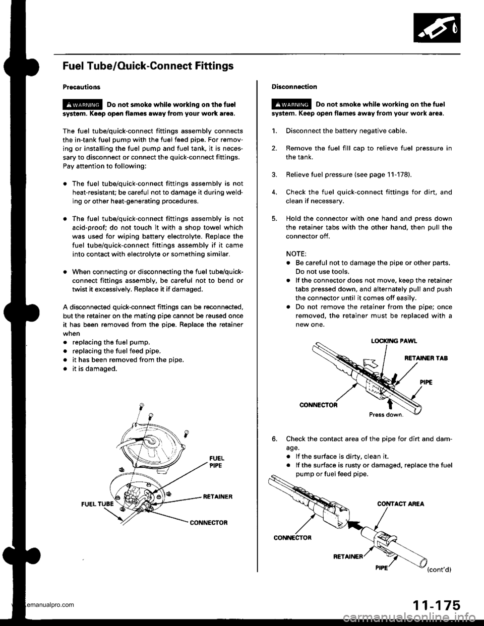
Fuel Tube/Ouick-Gonnect Fittings
Procautions
@ Do not smoke whils working on the fuel
syst6m, Koop open flames away from your work ar9a.
The fuel tube/quick-connect fittings assembly connects
the in-tank fuel pump with the fuel feed pipe. For remov-
ing or installing the fuel pump and fuel tank, it is neces-
sary to disconnect or connect the quick-connect fittings.
Pay attention to following;
. The fuel tube/quick-connect fittings assembly is not
heat-resistant; be careful not to damage it during weld-
ing or other heat-generating procedures.
. The fuel tube/quick-connect fittings assembly is not
acid-proof; do not touch it with a shop towel which
was used for wiping battery electrolyte. R€place the
fuel tube/quick-connect fittings assembly if it came
into contact with electrolyte or somethino similar.
. When connecting or disconnecting the fuel tube/quick-
connect fittings assembly, be careful not to bend or
twist it excessively, Replace it if damaged,
A disconnected quick-connect fittings can be reconnected,
but the retainer on the mating pipe cannot be reused once
it has been removed from the pipe. Replace tha retainer
. replacing the fuel pump.
. replacing the fuelfeed pipe,
. it has been removed from the Dioe,
. it is damaged.
RCTAINERFUEL TUBE
CONNECTOR
CONNECTOR
RETAINER
11-175
Disconnection
!@ Do not smoke while working on the fuel
syst6m. Keep open flames away from your work area.
1. Disconnect the battery negative cable.
2. Remove the fuel fill cap to relieve fuel pressure in
the tank.
3. Relieve fuel pressure (see page 11-178).
4. Check the fuel quick-connect fittings for dirt, and
clean if necessary.
5. Hold the connector with one hand and press down
the retainer tabs with the other hand. then pull the
connector off.
NOTE:
. Be careful not to damage the pipe or other parts.
Do not use tools,
. lf the connector does not move, keep the retainer
tabs pressed down, and alternately pull and push
the connector until it comes off easily.
. Do not remove the retainer from the pipe; once
removed, the retainer must be replaced with a
new one.
LOCKII{G PAWL
RETANEN TAB
@NNCCTOR
Press down.
6. Check the contact area of the pipe for dirt and dam-
age.
. lf the surface is dirW, clean it
. lf the surface is rusty or damaged, replace the fuel
pump or fuel feed pipe,
CONTACT ANEA
{cont'd}
www.emanualpro.com
Page 379 of 1395
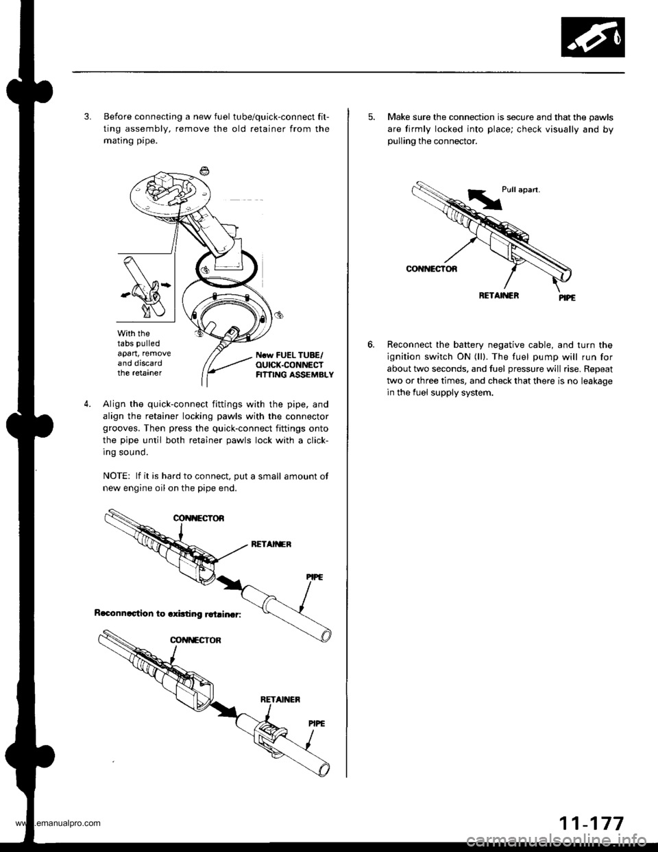
3. Before connecting a new fuel tube/quick-connect fit-
ting assembly, remove the old retainer from the
mating pipe.
with thetabs pulled
apart, removeand discardthe retarner
Ncw FUEL TUBE/OUICK.CONNECTFI?TING ASSEMBLY
4.Align the quick-connect fittings with the pipe. and
align the retainer locking pawls with the connector
grooves. Then press the quick-connect fittings onto
the pipe until both retainer pawls lock with a click-
Ing sound.
NOTE: lf it is hard to connect, put a small amount of
new engine oil on the pipe end.
5. Make sure the connection is secure and that the pawls
are firmly locked into place; check visually and bypulling the connector.
Reconnect the battery negative cable, and turn the
ignition switch ON (ll). The fuel pump will run for
about two seconds, and fuel pressure will rise. Repeat
two or three times, and check that there is no leakage
in the fuel supply system.
6.
www.emanualpro.com