flush HONDA CR-V 2000 RD1-RD3 / 1.G User Guide
[x] Cancel search | Manufacturer: HONDA, Model Year: 2000, Model line: CR-V, Model: HONDA CR-V 2000 RD1-RD3 / 1.GPages: 1395, PDF Size: 35.62 MB
Page 819 of 1395
Front Driveshafts
Removal (cont'd)
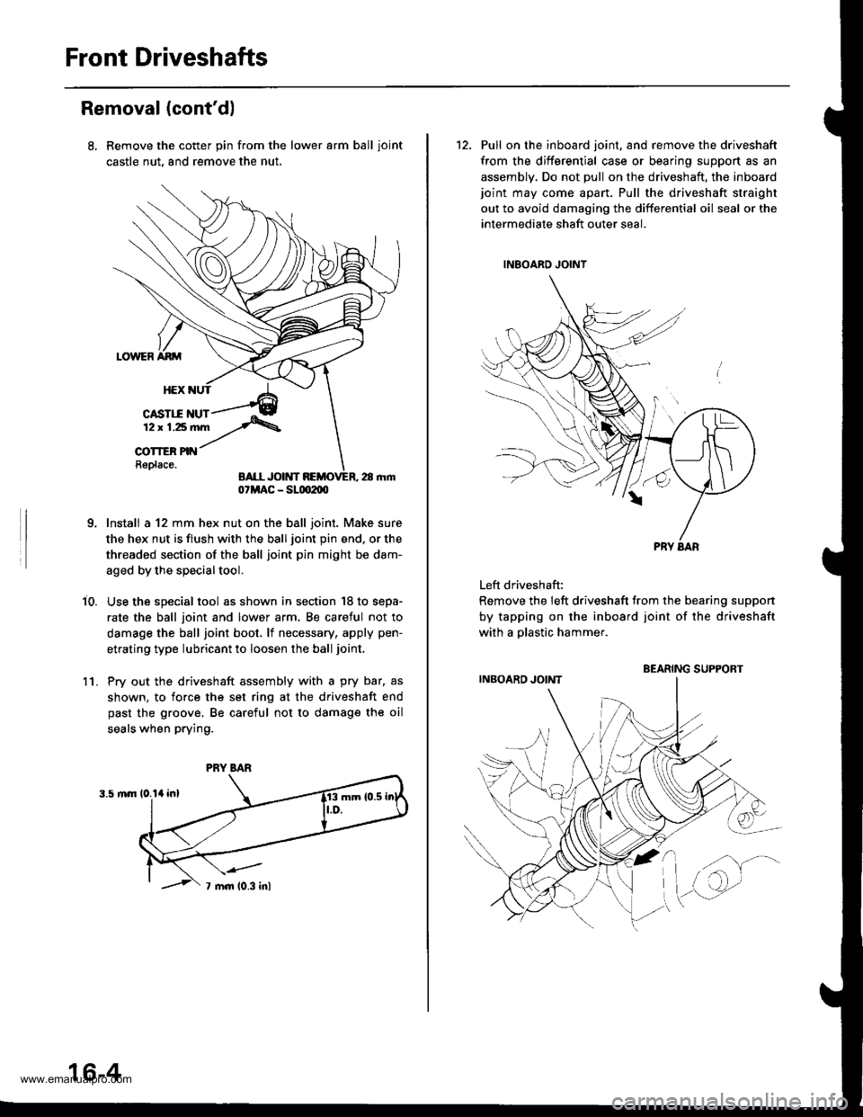
Remove the cotter pin from the lower arm ball ioint
castle nut, and remove the nut.
Install a 12 mm hex nut on the ball joint. Make sure
the hex nut is flush with the ball joint pin end, or the
threaded section of the ball joint pin might be dam-
aged by the special tool.
Use the special tool as shown in section '18 to sepa-
rate the ball joint and lower arm, Be caretul not to
damage the ball joint boot, lf necessary, apply pen-
etrating type lubricant to loosen the ball joint,
Pry out the driveshaft assembly with a pry bar, as
shown, to force the set ring at the driveshaft end
past the groove. Be careful not to damage the oil
seals when prying.
i0.
1l.
07MAC - SLm2m
PRY BAR
16-4
12. Pull on the inboard joint, and remove the driveshaft
from the differential case or bearing support as an
assembly. Do not pull on the driveshaft, the inboardjoint may come apart. Pull the driveshaft straight
out to avoid damaging the differential oil seal or the
intermediate shaft outer seal.
Left driveshaft:
Remove the left driveshaft from the bearing suppon
by tapping on the inboard joint of the driveshaft
with a olastic hammer.
BEARING SUPPORT
www.emanualpro.com
Page 836 of 1395
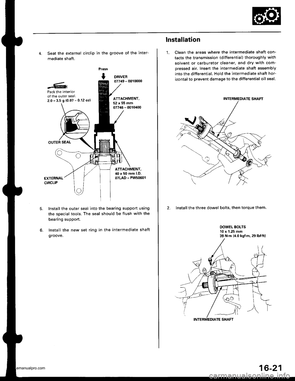
4. Seat the external circlip in the groove of the inter-
mediate shaft.
Press
+ DRNER07749 - 0010000
Pack the interiorof the outer seal.2.0- 3.5 9 {0.07 - 0.12 oz)
OUTER SEAL
ATTACHMENT,52x55mm07746- 0010400
ATTACHMENT.40 x 50 mm l.D.07LAD - PW50601EXTERNALCIRCLIP
6.
Install the outer seal into the bearing support using
the special tools. The seal should be flush with the
bearing support.
Install the new set ring in the intermediate shaft
groove.
lnstallation
1. Clean the areas where the intermediate shaft con-
tacts the transmission (differential) thoroughly with
solvent or carburetor cleaner, and dry with com-
pressed air. Insen the intermediate shaft assembly
into the differential. Hold the intermediate shaft hor-
izontal to prevent damage to the differential oil seal.
2. Install the three dowel bolts, then torque them.
OOWEL BOLTS10 x 1.25 mm39 N.m {4.0 kgf.m, 29 lbtftl
INTERMEOIATE SHAFT
16-21
www.emanualpro.com
Page 876 of 1395
Power Steering Gearbox
Removal
Note these items during removal:
. Using solvent and a brush, wash any oil and dirt off
the valve body unit its lines, and the end if the gear-
box. Blow dry with compressed air.
. Be sure to remove the steering wheel before discon-
necting the steering joint. Damage to the cable reel
can occur.
. With 4WD. tilt the engine with a jack to expand the
clearance between the transfer assembly and rear
beam when removing the steering gearbox from the
rear oeam.
Do not remove the steering gearbox by removing the
transfer assembly from the transmission.
1. Drain the power steering fluid as described on page'17-15.
Raise the vehicle, and suppon it on safety stands in
the proper locations (see section 1).
Remove the front wheels,
Remove the drive/s airbag assembly {see section 24).
Remove the steering wheel {see page 17-18).
Remove the steering joint bolts, then disconnect the
steering joint by moving the joint toward the column.
UPPER JOINT BOLT
LOWER JOINT BOLT
13.
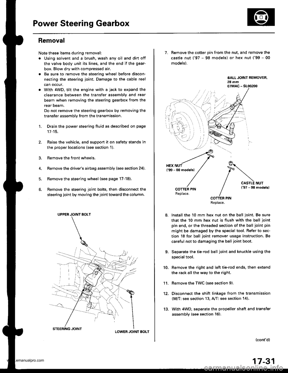
7. Remove the cotter pin from the nut, and remove the
castle nut {'97 - 98 models) or hex nut ('99 - 00
models).
COTTER PINReplace.
Install the 10 mm hex nut on the ball joint. Be sure
that the 10 mm hex nut is flush with the ball joint
pin end, or the threaded section of the ball joint pin
might be damaged by the special tool. Refer to sec-
tion 18 for ball joint remover usage instruction, Be
careful not to damaging the ball joint boot.
Separate the tie-rod ball joint and knuckle using the
special tool.
Remove the right and left tie-rod ends, then extend
the rack all the way to the right.
Remove the TWC (see section 9).
Disconnect the shift linkage from the transmission
(M/T: see section 13, A/T: see section 14).
With 4WD. separate the propeller shaft and transfer
assembly (see section 161.
10.
11.
(cont'd)
17-31
www.emanualpro.com
Page 909 of 1395
12.
13.
14.
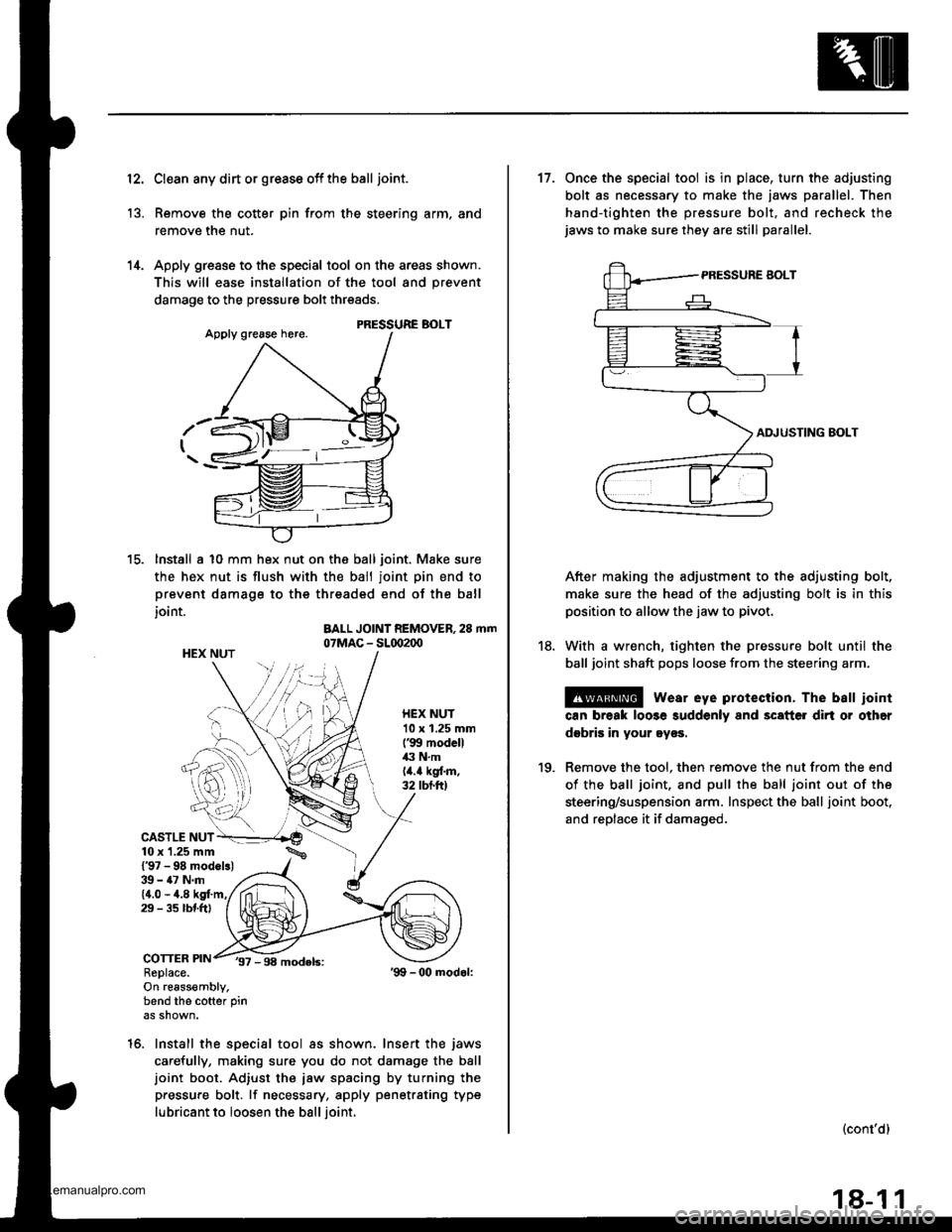
Clean any dirt or grease off the ball joint.
Remove the cotter pin from the steering arm, and
remove the nut.
Apply grease to the special tool on the areas shown.
This will ease installation of the tool and prevent
damage to the pressure bolt threads.
PRESSURE BOLT
lnstall a 10 mm hex nut on the ball joint. Make sure
the hex nut is flush with the ball joint pin end to
prevent damage to the threaded end of the ball
joint.
BALL JOINT REMOVER, 28 mm07MAC - SL(x)2(x)HEX NUT
HEX NUT10 x 1.25 mm('99 modcll43 N.mlit.a kgl.m.32 tbtft)
37 -98 models:
tc.
6:)
CASTLE NUT10 x '1.25 mm
l'97 - 98 modcls)39 - 47 N.m{4.0 - 4.829 - 3s rbtftt
COTTERReplace.On re6ss€mbly,bend the cofter pin
16. Install the special tool as shown. Insert the jaws
carefully, making sure you do not damage the balljoint boot. Adiust the jaw spacing by turning the
pressure bolt. lf necessary, apply penetrating type
lubricant to loosen the ball ioint.
'99 -00 modol:
18.
17. Once the special tool is in place, turn the adjusting
bolt as necessary to make the jaws parallel. Then
hand-tighten the pressure bolt, and recheck thejaws to make sure they are still parallel.
ADJUSTING BOLT
After making the adjustment to the adjusting bolt,
make sure the head of the adjusting bolt is in this
position to allow the jaw to pivot.
With a wrench, tighten the pressure bolt until the
ball joint shaft pops loose from the steering arm.
@ wear eye protection. The balt iointcan break loose suddenly and scatter dirt or other
dsbris in your ey€s.
Remove the tool, then remove the nut from the end
of the ball joint, and pull the ball joint out of the
steering/suspension arm. Inspect the ball joint boot.
and replace it if damaged.
(cont'dl
1(|
18-1 1
www.emanualpro.com
Page 910 of 1395
Front Suspension
Knuckle/Hub Replacement (cont'd)
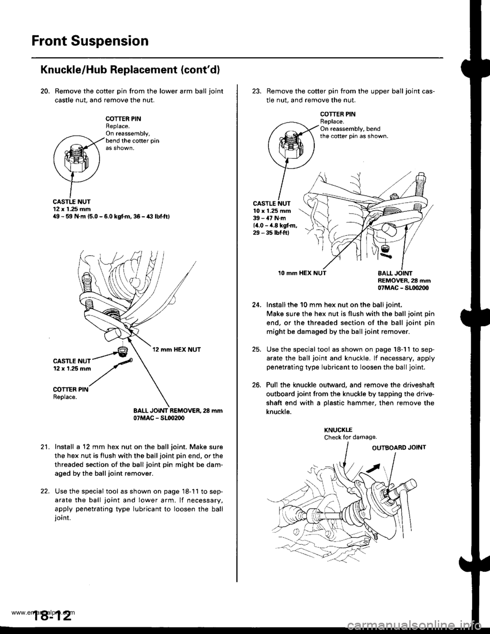
20. Remove the cotter pin from the lower arm ball joint
castle nut, and remove the nut.
COTTER PINReplace.On ra6ssembly,bend the cofter pin
CASTI.E NUT12 x 1.25 mmilg - 59 N.m (5.0 - 6.0 kgf.m, 36 - a3 lbf.ftl
CASTLE NUT12 x 1.25 mm
COITER PINReplace.
BALL JOINT REMOVER, 28 mm07MAC - Sl(xr2(x,
Install a 12 mm hex nut on the ball joint. Make sure
the hex nut is flush with the ball joint pin end, or the
threaded section of the ball joint pin might be dam-
aged by the ball joint remover.
Use the special tool as shown on page 18-11 to sep-
arate the ball joint and lower arm. lf necessary,
apply penetrating type lubricant to loosen the balljoint.
18-12
23. Remove the cotter pin from the upper ball joint cas-
tle nut, and remove the nut.
COTTER PINReplace.On reassembly, bendthe cotter pin as shown.
CASTLE NUT10 x 1.25 mm39 - 47 N.m14.0 - ,4.8 kgt m,29 - 35 tbt.ftl
24.
25.
26.
10 mmnEMOVER, 28 mm07MAC _ SLtD2(xl
Install the 10 mm hex nut on the ball joint.
Make sure the hex nut is flush with the ball joint pin
end, or the threaded section of the ball joint pin
might be damaged by the ball joint remover.
Use the special tool as shown on page 18-11 to sep-
arate the ball joint and knuckle. lf necessary, apply
penetrating type lubricant to loosen the ball joint.
Pull the knuckle outward, and remove the driveshaft
outboard joint from the knuckle by tapping the driv+
shaft end with a pl8stic hammer, then remove the
knuckle.
KNUCKI.ECheck lor damage.
www.emanualpro.com
Page 921 of 1395
Rear Damper
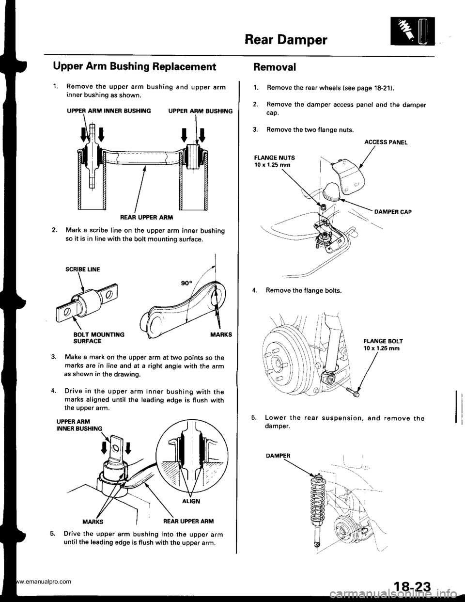
1.
Upper Arm Bushing Replacement
Remove the upper arm bushing and upper arminner bushing as shown.
UPPER ARM INNER BUSHING UPPER ARM AUSHIT{G
Mark a scribe line on the upper arm inner bushing
so it is in line with the bolt mounting surface.
BOLT MOUNTII{GSURFACE
Make a mark on the upper arm at two points so the
marks are in line and at a right angle with the arm
as shown in the drawing.
Drive in the upper arm inner bushing with themarks aligned until the leading edge is flush with
the uoDer arm.
Drive the upper arm bushing into the upper armuntil the leading edge is flush with the upper arm.
REAR UPPER ARM
5.
Removal
Remove the rear wheels (see page '18-21),
Remove the damper access panel and the damper
cap.
Remove the two flange nuts.
ACCESS PANEL
OAMPER CAP
't.
4. Remove the flange bolts.
Lower the rear suspension, and remove
damper.the
1a-23
www.emanualpro.com
Page 1003 of 1395
Doors
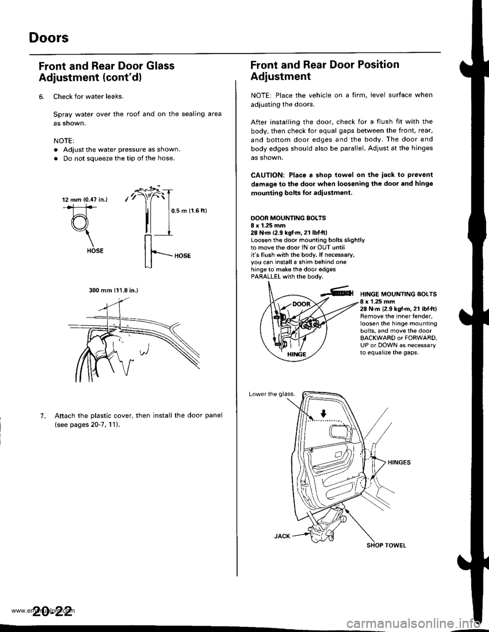
Front and Rear Door Glass
Adiustment (cont'dl
6. Check for water leaks.
Spray water over the roof and on the sealing area
as snown.
NOTE:
. Adjust the water pressure as shown.
. Do not soueeze the tio of the hose.
12 mm {0.47 in.l
#
(r\"1
HOSE
-"'*r"i
,'r)"f
tl
0.5 m (1.6 ftl
7. Attach the plastic cover, then install the door panel
(see pages 20-7, 'l 1),
20-22
..-
300 mm 111.8 in.)
Front and Rear Door Position
Adjustment
NOTE: Place the vehicle on a firm, level surface when
adiusting the doors.
After instailing the door, check for a flush fit with the
body, then check lor equal gaps between the front, rear.
and bottom door edges and the body. The door and
body edges should also be parallel. Adjust at the hinges
as shown.
CAUTION: Placa a shop towel on the iack to prevent
damage to the door when loosening the door and hinge
mounting bolts lor adiustment.
DOOR MOUNTING BOLTSI x 1.25 mm28 N.m 12.9 kgtr.m, 21 lbI.ftlLoosen the door mounting bolrs slighrlyto movethe door lN or OUT untilit's flush with the bodv. lf necessary,you can installa shim behind onehinge to make the door edgesPARALLEL with the bodv.
HINGE MOUNTING BOLTS8 x 1.25 mm28 N,m 12.9 kgt.m. 21 lbl.ftlRemove the inner fender,loosen the hinge mountingbolts, and move the doorBACKWARD or FORWARD,UP or DOWN as necessaryto equalize the gaps.
Lower the glass.
www.emanualpro.com
Page 1004 of 1395
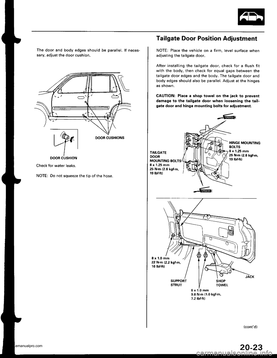
The door and body edges should be parallel. lf neces-
sary, adjust the door cushion.
ry.DOOR CUSHION
Check for water leaks.
NOTE: Do not squeeze the tip ofthe hose.
oooR cusHroNs
Tailgate Door Position Adjustment
NOTE: Place the vehicle on a firm, level surface when
adjusting the tailgate door.
After installing the tailgate door. check for a flush fit
with the body, then check for equal gaps between the
tailgate door edges and the body. The tailgate door and
body edges should also be parallel. Adjust at the hinges
as snown.
CAUTION: Place a shop towel on the iack lo prevent
damage to the tailgale door when loos€ning the tail-
gate door and hinge mounting bolts for adiustment.
TAILGATEDOORMOUNTING sOLTS8 x 1.25 mm25 N.m {2.6 kgf.m,19 tbf.ft)
HINGE MOUNYINGBOLTS8 x 1.25 mm25 N.m 12.6 kgt m,19 rbf.ftl
8x1.0mm22 N'rrl� 12.2 kgl.m,16 tbt.ftl
6xl.0mm9.8 N.m {1.0 kgt m,1.2 tbl.ltl
(cont'd)
20-23
www.emanualpro.com
Page 1005 of 1395
Doors
(cont'd)
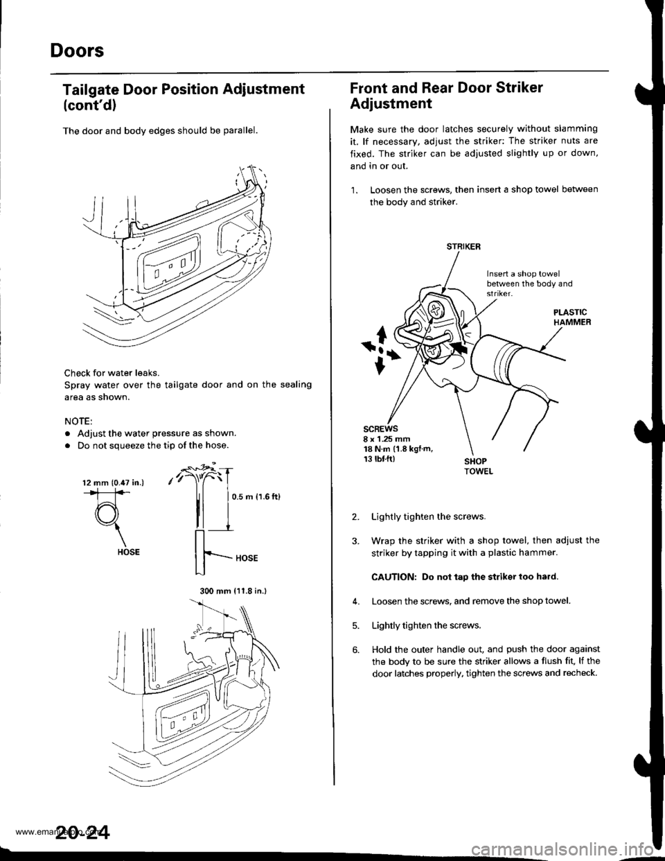
The door and body edges should be parallel.
Check for water leaks.
Spray water over the tailgate door and on the sealing
area as shown.
NOTE:
. Adjust the water pressure as shown.
. Do not squeeze the tip ofthe hose.
Tailgate Door Position Adiustment
-€*4
,'r)"C
II
0.5 m {1.6 ft}
20-24
l2 mm (0.47 in.).*1:]*
d3"1
HOSE
300 mm {11.8 in.l
Front and Rear Door Striker
Adjustment
Make sure the door latches securely without slamming
it, lf necessary, adjust the striker: The striker nuts are
fixed. The striker can be adjusted slightly up or down,
and in or out.
1. Loosen the screws, then insert a shop towel between
the body and striker.
Insert a shop towelbetween the body and
scREws8 x 1 .25 mm18 N.m (1.8 kgt.m,13 rbf.ft)
2.
J.
Lightly tighten the screws.
Wrap the striker with a shop towel, then adjust the
striker by tapping it with a plastic hammer.
CAUTION: Do not tap the striksr loo hard.
Loosen the screws. and remove the shop towel.
Lightly tighten the screws.
Hold the outer handle out, and push the door against
the body to be sure the striker allows a flush fit, lf the
door latches properly. tighten the screws and recheck.
4.
5.
6.
STRIKER
www.emanualpro.com
Page 1006 of 1395
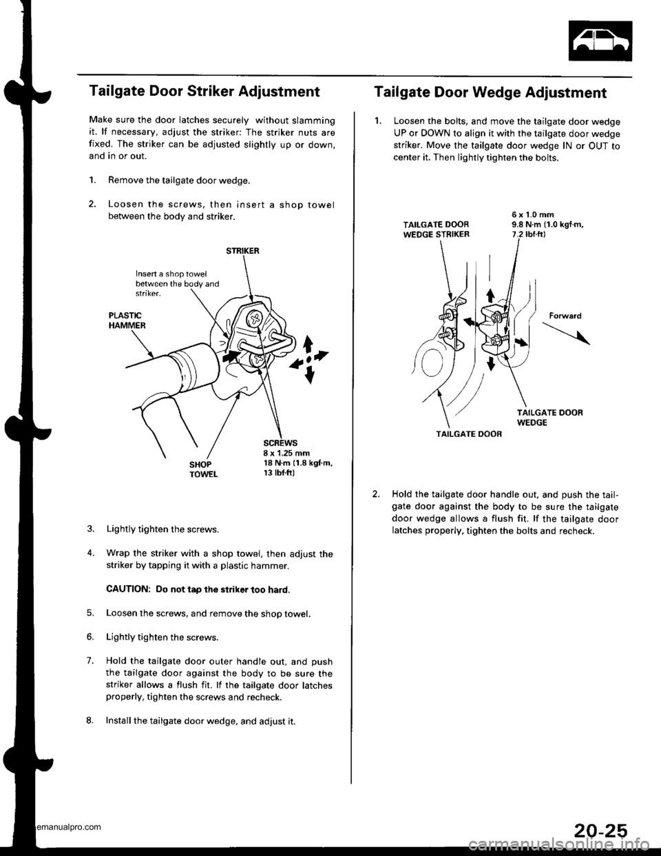
Tailgate Door Striker Adjustment
Make sure the door latches securely without slamming
it. lf necessary, adjust the striker: The striker nuts are
fixed. The striker can be adjusted slightly up or down,
and in or out.
1. Remove the tailgate door wedge.
2. Loosen the screws, then insert a shop towel
between the body and striker.
8 x 1.25 mm18 N.m (1.8 kgf.m,r 3 tbf.ft)
1.
4.
Lightly tighten the screws.
Wrap the striker with a shop towel, then adjust the
striker by tapping it with a plastic hammer.
CAUTION: Do not tap the striker too hard.
Loosen lhe screws, and remove the shop towel.
Lightly tighten the screws.
Hold the tailgate door outer handle out, and push
the tailgate door against the body to be sure thestriker allows a flush fit. lf the tailgate door latchesproperly, tighten the screws and recheck.
Install the tailgate door wedge, and adjust it.
STRIKER
Insen a shoptowelbetween the body and
Tailgate Door Wedge Adjustment
1. Loosen the bolts, and move the tailgate door wedge
UP or DOWN to align it with the tailgate door wedge
striker. Move the tailgate door wedge lN or OUT to
center it. Then lightly tighten the bolts.
TAILGATE OOOR
Hold the tailgate door handle out, and push the tail-gate door against the body to be sure the tailgate
door wedge allows a flush fit. lf the tailgate door
latches properly, tighten the bolts and recheck.
Forward
20-25
www.emanualpro.com