length HONDA CR-V 2000 RD1-RD3 / 1.G User Guide
[x] Cancel search | Manufacturer: HONDA, Model Year: 2000, Model line: CR-V, Model: HONDA CR-V 2000 RD1-RD3 / 1.GPages: 1395, PDF Size: 35.62 MB
Page 82 of 1395
Charging System
IRectifier Test
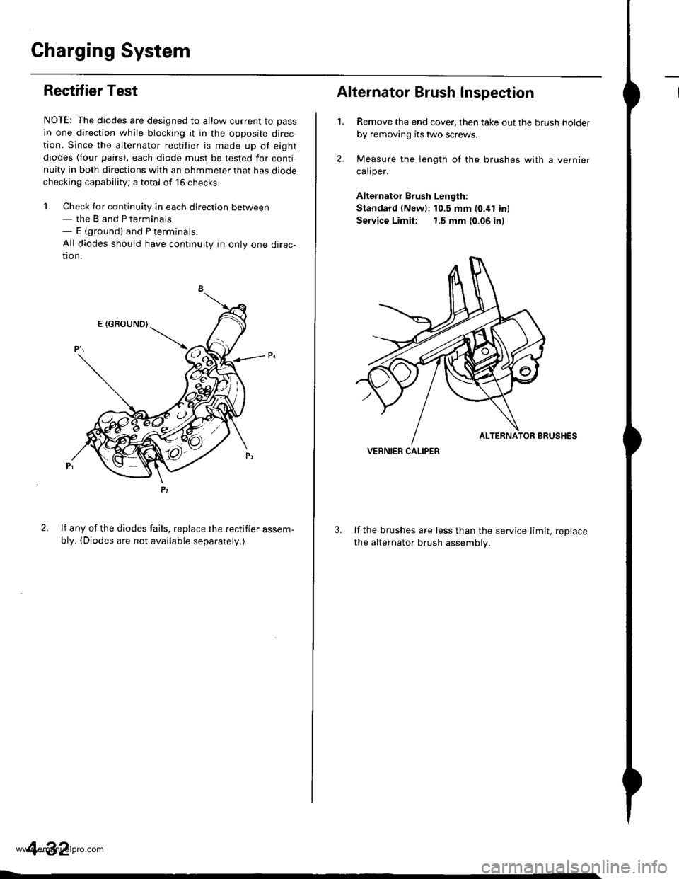
NOTE: The diodes are designed to allow current to pass
in one direction while blocking it in the opposite direc
tion. Since the alternator rectifier is made up of eight
diodes (four pairs), each diode must be tested for continuity in both directions with an ohmmeter that has diode
checking capability; a total of 16 checks.
'l. Check for continuity in each direction between- the B and P terminals.- E (ground) and P terminals.
All diodes should have continuity in only one direc-
tion.
2. lf any of the diodes fails, replace the rectifier assem-
bly. (Diodes are not available separatelv.)
4-32
1.
Alternator Brush Inspection
2.
Remove the end cover, then take out the brush holder
by removing its two screws.
Measure the length of the brushes with a vernier
calrper.
Alternator Brush Length:
Standard (Newl:10.5 mm 10.41 inl
Service Limit: 1.5 mm {0.06 in)
lf the brushes are less than the service limit, replace
the alternator brush assemblv.
VERNIER CALIPER
www.emanualpro.com
Page 140 of 1395
Cylinder Head
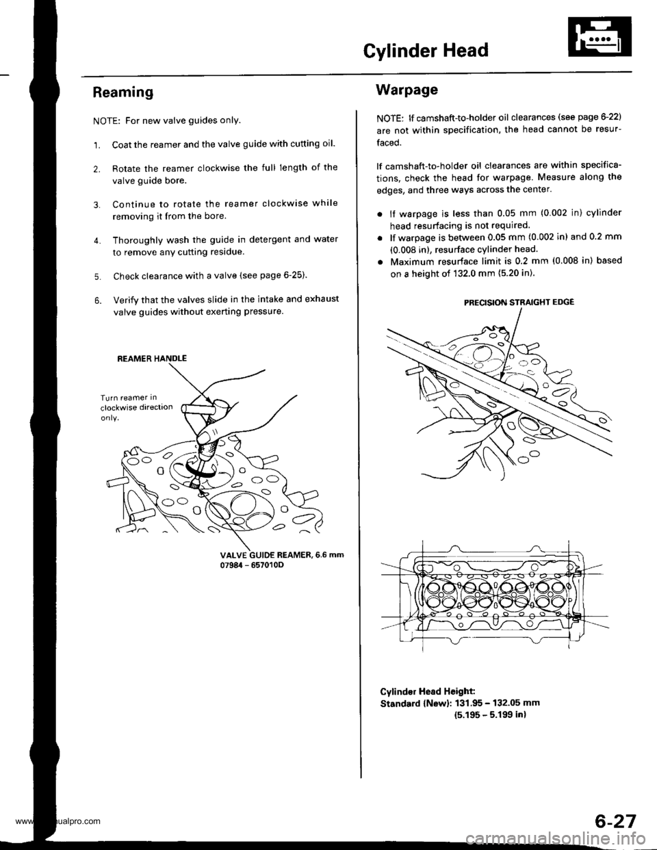
Reaming
NOTE: For new valve guides only.
1. Coat the reamer and the valve guide with cutting oil.
2. Rotate the reamer clockwise the full length of the
valve guide bore.
Continue to rotate the reamer clockwise while
removing it from the bore.
Thoroughly wash the guide in detergent and water
to remove anY cutting residue.
Check clearance with a valve (see page 6-25).
Verify that the valves slide in the intake and exhaust
valve guides without exerting pressure.
3.
4.
5.
6.
vALvE GUIDE REAMER,6.6 mm0798i1 - 657010O
REAMER HANDLE
e
Warpage
NOTE: lf camshaft-to-holder oil clearances (see page G22)
are not within specification, the head cannot be resur-
faced.
lf camshaft-to-holder oil clearances are within specifica-
tions, check the head for warpage. Measure along the
edges, and three ways across the center.
. if warpage is less than 0.05 mm (0.002 in) cylinder
head resurfacing is not required
lf warpage is between 0.05 mm (0.002 in) and 0.2 mm
(0.008 in), resurface cylinder head.
Maximum resurface limit is 0.2 mm (0.008 in) based
on a height of 132.0 mm (5.20 in).
Cylind€r Hesd Height:
Standard {New}: 131.95 - 132.05 mm
15.195 - 5.199 inl
PRECISION STRAIGHT EDGE
6-27
www.emanualpro.com
Page 160 of 1395
Piston PinsConnecting Rods
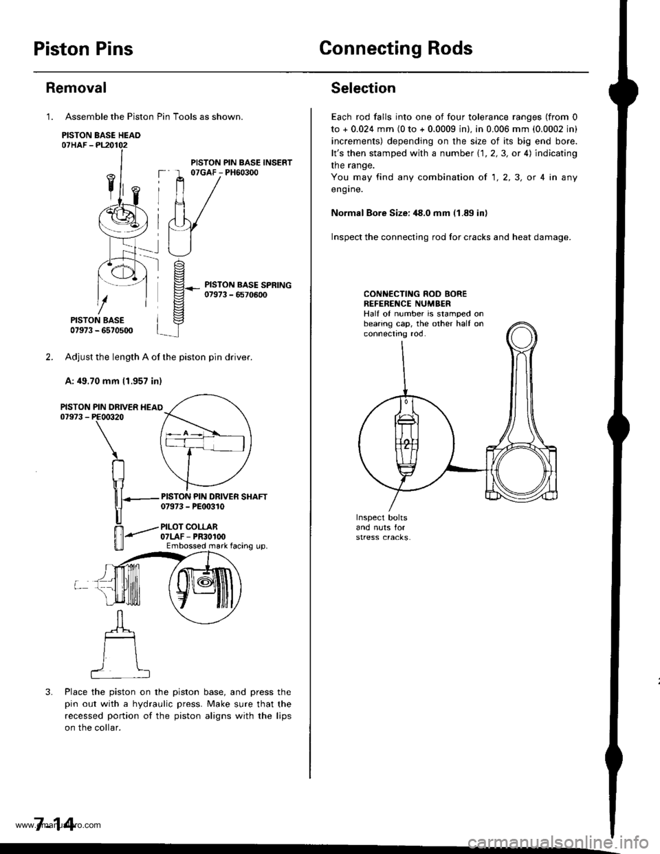
Assemble the Piston Pin Tools as shown.
PISTON BASE HEAO07HAF -PL20102
PISTON BASE07973 - 6570500
Adjust the length A of the piston pin dflver.
A: 49.70 mm 11.957 in)
PIN DRIVER HEAIPE00320
\
RIr1
nT---
u
ffi-"""-
u_ll
3. Place the piston on the piston base, and press the
pin out with a hydraulic press. Make sure that the
recessed portion of the piston aligns with the lips
on the collar.
7-14
Removal
1.
PISTON07973 -
PISTON PIN BASE INSERT07GAF - PH60300
PISTON PIN DRIVER SHAFT07973 - PEt 0310
PILOT COLLAR07LAF - PR30100Embossod mark facing up.
Selection
Each rod falls into one of four tolerance ranges (from 0
to + 0.024 mm {0 to + 0.0009 in). in 0.006 mm (0.0002 in)
increments) depending on the size of its big end bore.
lt's then stamped with a number 1.1.2,3, or 4) indicating
the range.
You may find any combination ot 1,2,3, or 4 in any
engrne.
Normal Bore Size: ,18.0 mm (1.89 in)
Inspect the connecting rod for cracks and heat damage.
CONNECTING ROD BOREREFENENCE NUMBERHalf of number is stamped onbearing cap, the other half onconnectno roo.
www.emanualpro.com
Page 161 of 1395
Piston Pins
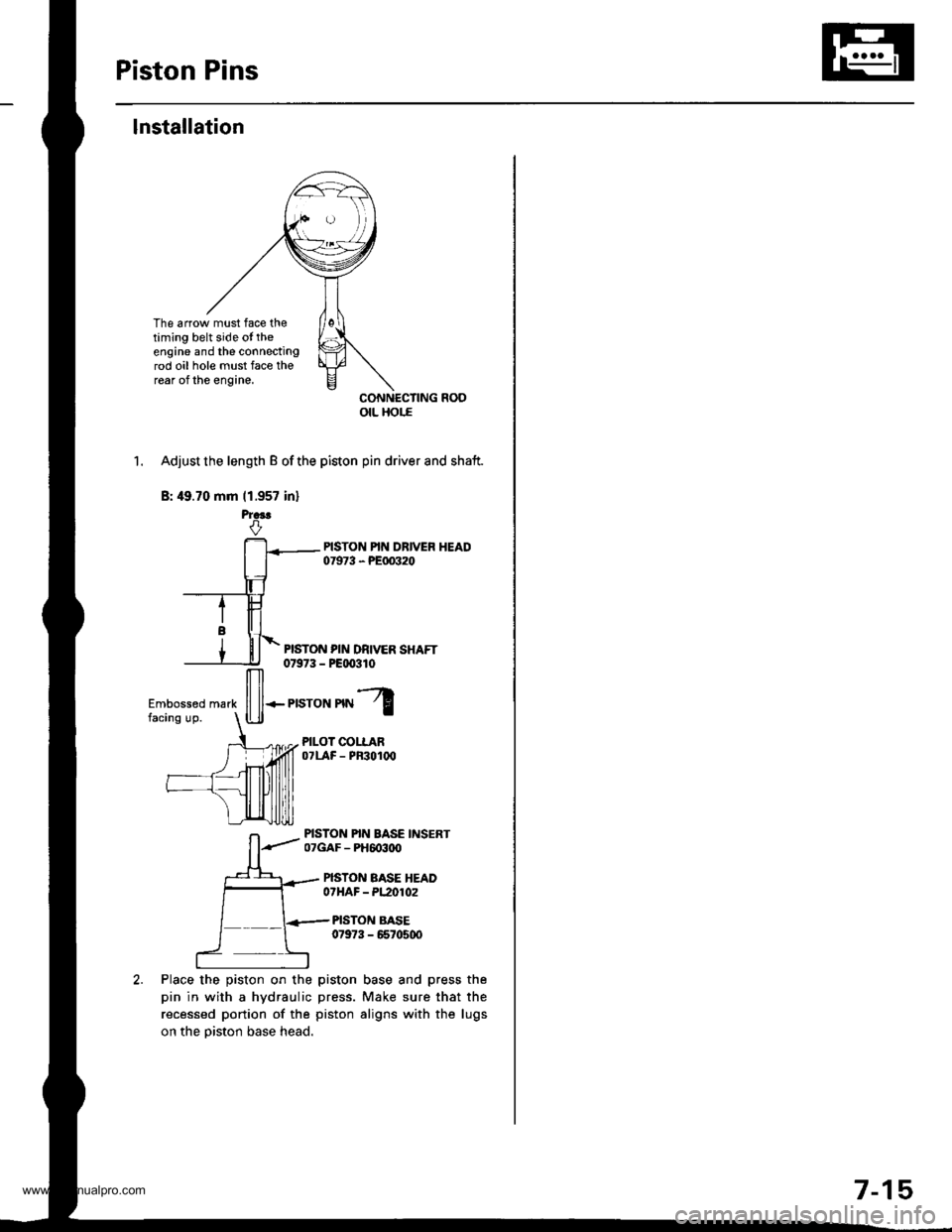
lnstallation
The arrow must face thetiming belt side ot theengine and the connectingrod oil hole must face therear of the engine.
CONNECTING ROOotL Hor.E
1. Adjust the length B of the piston pin driver and shaft.
B: 49.70 mm (1.957 in)
PISTON PIN DRIVER SHAFT0t973 - P€qxtlo
Place the piston on the
pin in with a hydraulic
recessed portion of the
on the piston base head.
ffi*r,"ron'nl
PILOT COLLAROTLAF - PF3O1(x'
PISTON PIN BASE INSERT07GAF - PH6o3ttO
PISTON BASE HEADOTHAF - PL2O102
PISTON BASE07973 - 6670500
piston base and press the
press. Make sure that the
piston aligns with the lugs
7-15
www.emanualpro.com
Page 713 of 1395
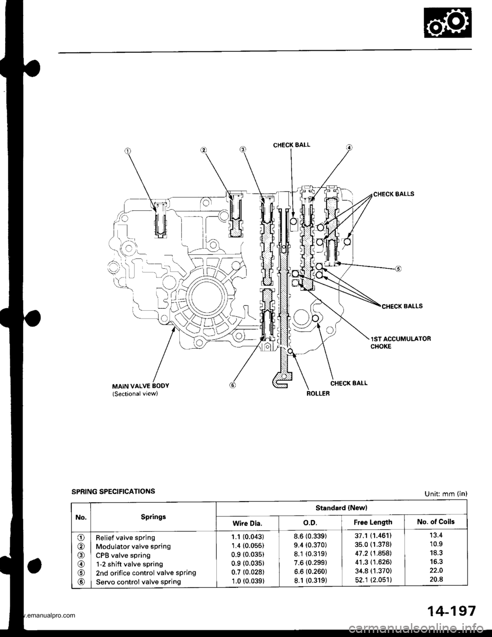
CHECK BALL
i)L)
lo
CHECK BALLS
lST ACCUMULATORCHOKE
CHECK EALLMAIN VALVE BODY(Sectionalview)
SPRING SPECIFICATIONSUnit: mm (in)
No.Springs
Standard {New)
Wire Dia.o.D.Froe LengthNo. of Coils
o
@
@
@
Relief valve spring
Modulator valve spring
CPB valve spring
1-2 shift valve spring
2nd orifice control valve spring
Servo control valve sPring
1.1 (0.043)
1.4 (0.055)
0.9 (0.03s)
0.9 (0.035)
0.7 (0.028)
1.0 t0.039)
8.6 (0.339)
9.4 (0.370)
8.1 (0.319)
7.6 (0.299)
6.6 (0.260)
8.1 {0.319)
37.1 (1.461)
35.0 (1.3781
41 .2 \1 .8581
41.3 (1.626)
34.8 (1.370)
52.1 (2.051)
'13.4
10.9
20.8
14-197
www.emanualpro.com
Page 714 of 1395
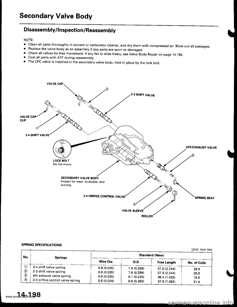
Secondary Valve Body
Disassembly/lnspection/Reassembly
NOTE:
' clean all parts thoroughly in solvent or carburetor cleaner. and dry them with compressed air. Blow out aU passages,. Replace the valve body as an assembly if any parts are worn or damaged.t check all valves for free movement. rf anyfair to sride freery. see varve Body Repair on page 14-192.. Coat all parts with ATF during reassembly.. The CPC valve is installed in the secondary valve body, held in place by the lock bolt.
@,.-.t'tr.,
,rr'^'//u
"/ ./
3-' SHIFT VALVE
VALVE CAP
SPRING SPEC!FICATIONS
2.3 SHIFT VALVE
VALVE SLEEVE
ROLLER
ilTH EXHAUST VALVE
N"*,"o"*,
Unit: mm (in)
t*-1
SECONOARY VALVE BODYInspect for wear, scratches, andscorang.
3.4 ORIFICE CONTROL VAL
No.SpringsStandald {Nswl
Wire Dia.o.D.Free LengthNo. of Coils
o
@
o
@
3 4 shift valve spring
2-3 shift valve spring
4th exhaust valve spring
3-4 orifice control valve spring
0.9 (0.035)
0.9 (0.035)
0.9 {0.035)
0.6 {0.024}
7.6 (0.299)
7.6 (0.299)
6.1 (0.240t
6.6 (0.2601
57 .O i.2.2441
57 .O 12.244J
36.4 (1.433)
37.9 (1.492)
26.A
26.8
19.5
31.6
14-198
www.emanualpro.com
Page 715 of 1395
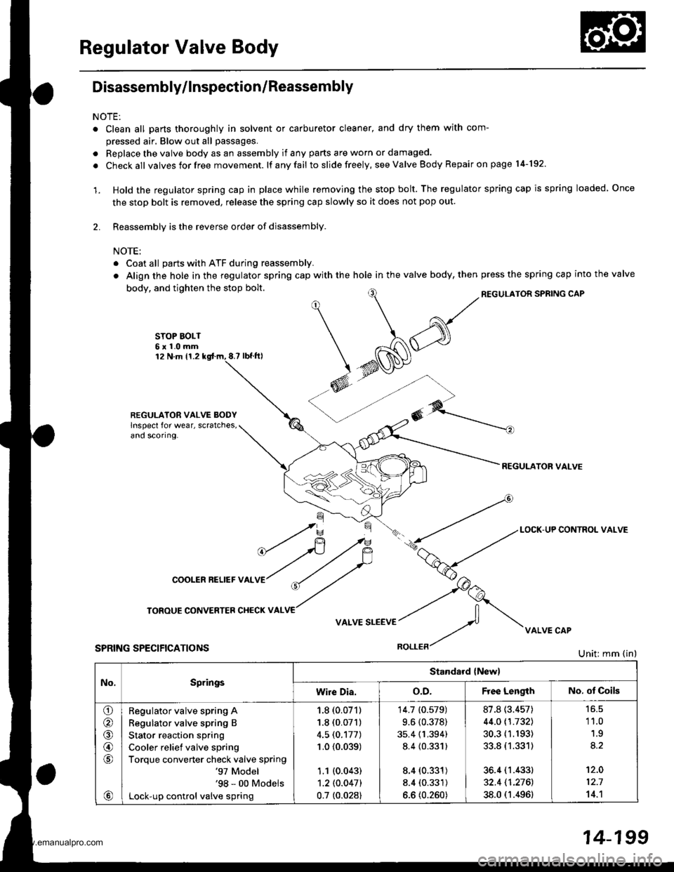
Regulator Valve Body
Disassembly/lnspection/Reassembly
NOTE:
o Clean all parts thoroughly in solvent or carburetor cleaner, and dry them with com-
pressed air. Blow out all passages.
. Replace the valve body as an assembly if any parts are worn or damaged.
. Checkall valvesforfree movement. lf anyfail toslidefreely, see Valve Body Repair on page l4-192.
'1. Hold the regulator spring cap in place while removing the stop bolt. The regulator spring cap is spring loaded Once
the stop bolt is removed, release the spring cap slowly so it does not pop out.
2. Reassembly is the reverse order of disassembly.
NOTE:
. Coat all parts with ATF during reassembly.
. Align the hole in the regulator spring cap with the hole in the valve body, thenpress the spring cap into the valve
REGULATOR SPSING CAPbody, and tighten the stop bolt.
STOP BOLT6x1.0mm12 N.m 11.28.? tbt.fil
REGULATOR VALVE BODYlnspect for wear, scratches,ano scoflng.
REGULATOR VALVE
No,SpringsStandard {New}
wire Dia.o.D.F ee LengthNo. ot Coils
o
@
@,6
a,
Regulator valve spring A
Regulator valve spring B
Stator reaction spring
Cooler relief valve spring
Torque converter check valve spring'97 Model'98 - 00 Models
Lock-up control valve spring
1.8 (0.071)
1.8 (0.071)
4.5 (0.177)
1.0 {0.039)
1.1 (0.043)
1.2lO.O47l
0.7 t0.028)
14.7 (0.579)
9.6 (0.378)
35.4 (1.394)
8.4 {0.331)
8.4 (0.331)
8.4 (0.331)
6.6 (0.260)
87.8 (3.457)
44.0 t1.7321
30.3 (1.193)
33.8 (1.331)
36.4 (1.433)
32.4 11.2761
38.0 (1.496)
'11.0
1.9
't2.0
12.7
14.'l
14-199
www.emanualpro.com
Page 717 of 1395
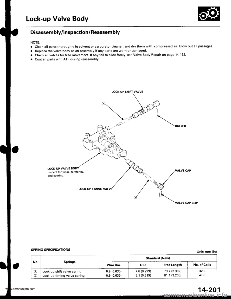
Lock-up Valve Body
Disassembly/lnspection/Reassem bly
NOTE:
. Clean all parts thoroughly in solvent or carburetor cleaner, and dry them with compressed air. Blow out all passages.
. Replace the valve body as an assembly if any parts are worn or damaged.
. Checkall valvesforfree movement. lf anyfailto slide freely, seeValve Body Repairon page 14-192.
. Coat all parts with ATF during reassembly.
LOCK.UP SHIFT VALVE
\/'
\-.xlO
@-tr
, ^ ,As'. \"o...*
LOCK-UP VALVE EODY
Inspect lor wear, scratches,
and scoring.
VALVE CAP
\uo.*"or".,,
LOCK-UP TIMING VAL
SPRING SPECIFICATIONSUnit: mm (in)
No.SpringsStandard lNewl
Wire Dia.o.D.Fle€ LengthNo. of Coils
O(Lock up shift valve spring
Lock-up timing valve spring
0.9 (0.035)
0.9 (0.035)
7.6 (0.299)
8.1 (0.319)
73.1 t2.902),
81.4 (3.205)
32.0
47 .8
14-201
www.emanualpro.com
Page 825 of 1395
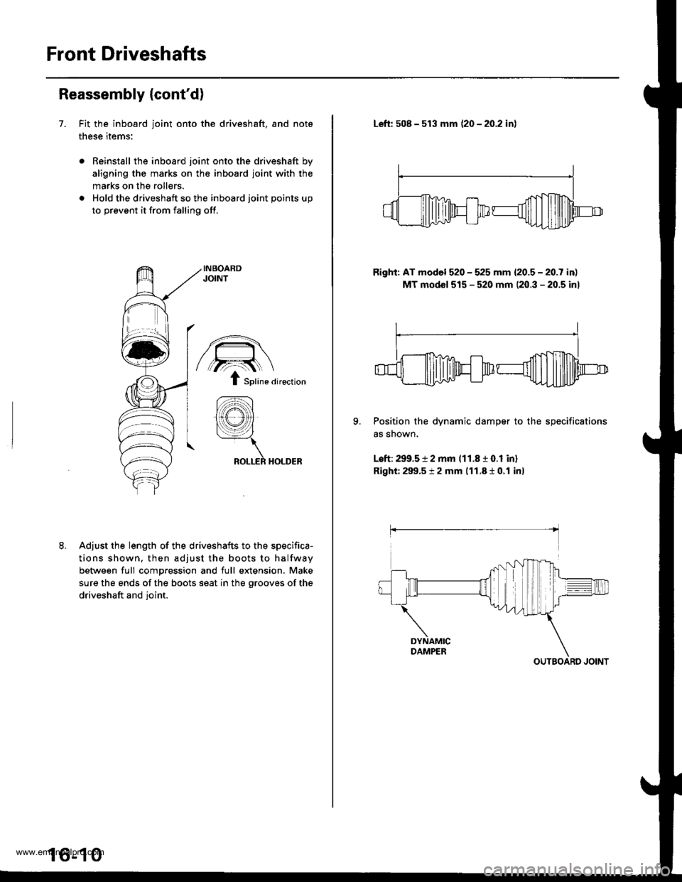
Front Driveshafts
Reassembly {cont'd)
7. Fit the inboard joint onto the driveshaft, and note
these items:
Reinstall the inboard joint onto the driveshaft by
aligning ths marks on the inboard joint with the
marks on the rollers.
Hold the driveshaft so the inboard joint points up
to prevent it from falling off.
Adjust the length of the driveshafts to the specifica-
tions shown. then adjust the boots to halfway
between full compression and full e)dension. Make
sure the ends of the boots seat in the grooves of the
driveshaft and Ioint.
/€\
/,?:..�{ \
t Sptine airection
lffi
tYl:\
ROLLER HOLDER
16-10
Left: 508 - 513 mm 120 - 2O.2 inl
Right: AT model 520 - 525 mm {20.5 - 20.7 in)
MT mod6l 515 - 520 mm (20.3 - 20.5 inl
II
-flm+dm@
9. Position the dynamic damper to the specifications
as snown.
Left: 299.5 t 2 mm 111.8 r O.l inl
Right: 299.5 t 2 mm 111.810.1 inl
OUTBOARO JOINT
www.emanualpro.com
Page 840 of 1395
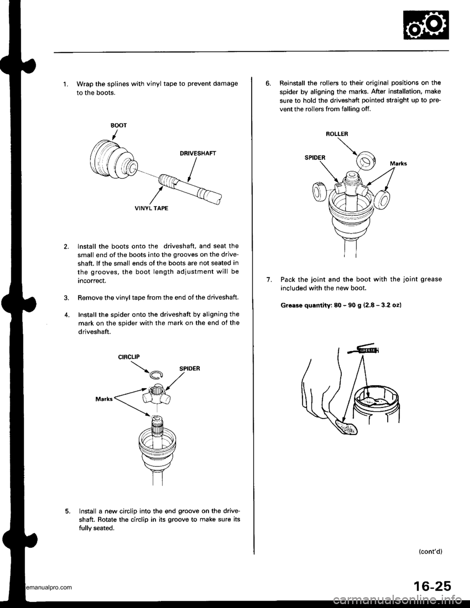
'1. Wrap the splines with vinyl tape to prevent damage
to the boots.
lnstall the boots onto the driveshaft, and seat the
small end of the boots into the grooves on the drive-
shaft, lf the small ends of the boots are not seated in
the grooves, the boot length adiustment will be
rncorrect.
Remove the vinyl tape from the end of the driveshaft.
Install the spider onto the driveshaft by aligning the
mark on the spider with the mark on the end of the
driveshaft.
lnstall a new circlip into the end g.oove on the drive-
shaft. Rotate the circlip in its groove to make sure its
fullv seated.
VINYL TAPE
6. Reinstall the rollers to their original positions on the
spider by aligning the marks. After installation, make
sure to hold the driveshaft pointed straight up to pre-
vent the rollers from falling off.
Pack the joint and the boot with the joint grease
included with the new boot.
Grease quantity: 80 - 90 s {2.8 - 3.2 o2)
7.
ROLLER
(cont'd)
16-25
www.emanualpro.com