Alternator HONDA CR-V 2000 RD1-RD3 / 1.G Owner's Manual
[x] Cancel search | Manufacturer: HONDA, Model Year: 2000, Model line: CR-V, Model: HONDA CR-V 2000 RD1-RD3 / 1.GPages: 1395, PDF Size: 35.62 MB
Page 179 of 1395
1.
2.
3.
RemovaUlnspection/lnstallation
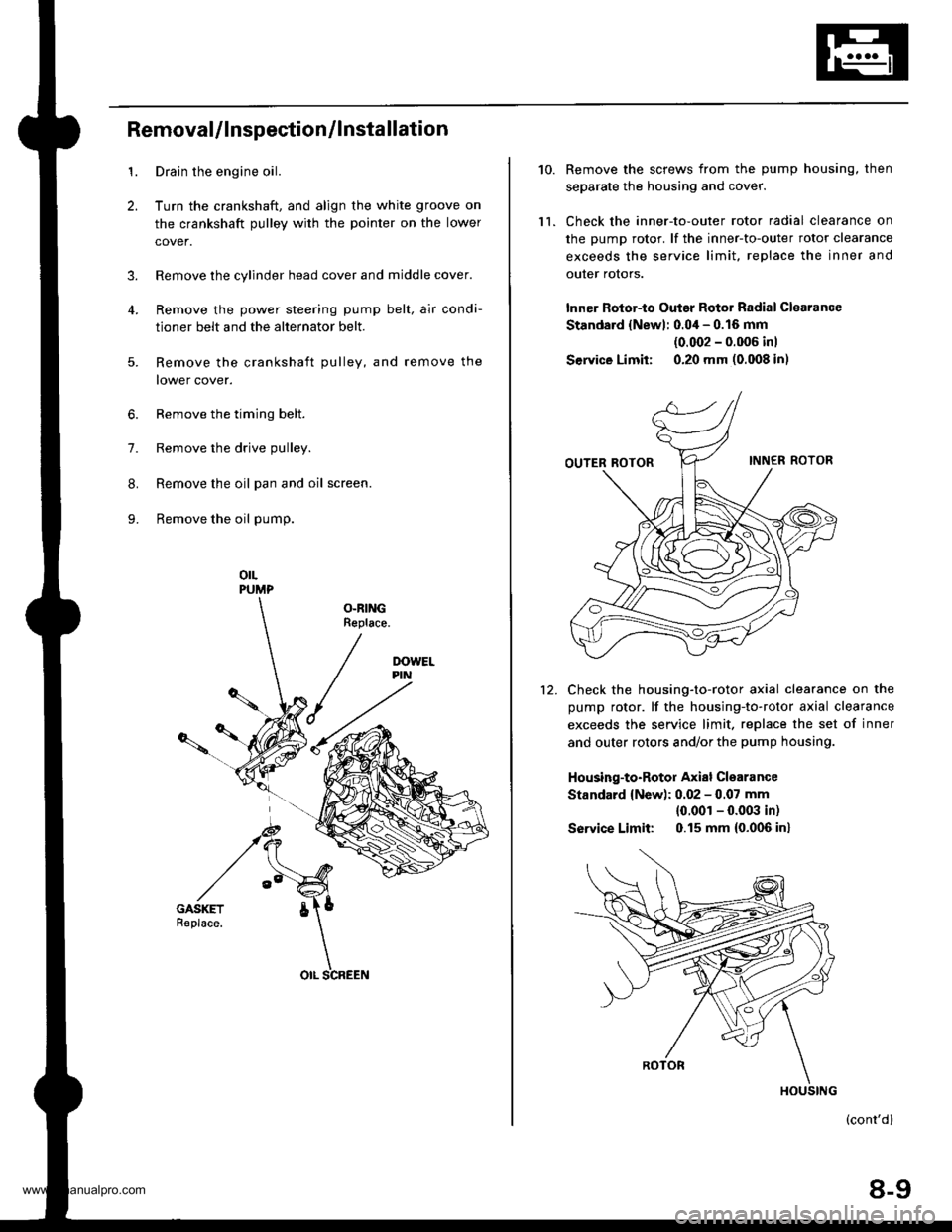
Drain the engine oil.
Turn the crankshaft, and align the white groove on
the crankshaft pulley with the pointer on the lower
cover.
Remove the cylinder head cover and middle cover.
Remove the power steering pump belt, air condi-
tioner belt and the alternator belt.
Remove the crankshaft pulley, and remove the
lower cover.
6. Remove the timing belt.
7. Remove the drive pulley.
8. Remove the oil pan and oil screen.
9. Remove the oil pump.
orLPUMP
OLRINGReplace.
5.
OIL SCREEN
10.
ll.
Remove the screws from the pump housing, then
separate the housing and cover.
Check the inner-to-outer rotor radial clearance on
the pump rotor. lf the inner-to-outer rotor clearance
exceeds the service limit. replace the inner and
outer rotors.
lnner Rotor-to Outar Rotor Radial Clearance
Standard {Newl: 0.04 - 0.16 mm
{0.002 - 0.006 inl
Service Limit: 0.20 mm (0.008 in)
Check the housing-to-rotor axial clearance on the
pump rotor. lf the housing-to-rotor axial clearance
exceeds the service limit. replace the set of inner
and outer rotors and/or the pump housing.
Housing-to-Rotor Axial Clearance
Standard {New): 0.02 - 0.07 mm
{0.001 - 0.003 in)
So|'�ice Limit: 0.15 mm (0.006 inl
(cont'd)
8-9
HOUSING
www.emanualpro.com
Page 204 of 1395

Fuel and Emissions
Special Tools ...................... 11-2
Component Locations
lndex ...................... ....,.... 11-3
Svstem Description
Vacuum Connections ...........,....,.,................. 1 1-9
Electrical Connections ................................... 1 1-15
System Connectors .,.,,.,............................,.,. 1 1-36
Troubleshooting
Troubleshooting Procedures,.,..................... 11-60
Engine Control Module/Powertrain ConttolModule Terminal Arrangement .............., 11-67
Diagnostic Trouble Code Chart .................... 1 t-75
How to Read Flowcharts .......,.....,.,............... I 1-79
PGM-Fl System
System Description .................,.,.,,,............... 1 1-80
Troubleshooting Flowcharts
Engine Control Module/PowertrainControl Module ........11-52
Manifold Absolute Pressure Sensor ............. 11-90
Intake Air Temperature Sensor .................... 1 1-95
Engine Coolant Temperature Sensor .,..,.,.... 1 1-99
Throttle Position Sensor ...........,.....,.,.,..,...... I 1'103
Primary Heated Orygen Sensor (Sensor 1) ... 11-110
Secondary Heated Oxygen Sensor{Sensor 2l .................. 1 1-117
Heated Oxygen Sensor Heater ..................... 11-121
Fuef Supply System ......11-124
Random Misfire ,....,.,..... 11-126
Mistire Detected in One Cylinder .....-........... 11-128
Knock Sensor ................ 11-130
CKP/TDC/CYP Sensor .................................... 1 1-131
Vehicle Speed Sensor ...............................,.... 1 1-135
Barometric Pressure Sensor .....,...,...,.,,........ 1 1-137
Electrical Load Detector ...,.,.......................... 1 1-138
CKF Sensor ................,.,, '11-112
ECM/PCM lnternaf Circuit ............................. 11'117
HO2S Replacement .,.,.,. 11-148
ldle Control System
System Description ............ 11-149
Troubleshooting Flowcharts
ldle Control System ...... 11-150
fdle Air Control Valve ......................,............. 11-152
Air Conditioning Signal ................................. I 1-155
Alternator FR Signal ...................................... 1 1-159
Starter Switch Si9na1 .................................... t l-161
Power Steering Pressure Switch Signal ...... 11-162
Brake Switch Si9na1 ...................................... 11-166
Fast ldle Thermo Valve .,.,.............................,.,.,. 11-168
ldle speed setting .............. 11-169
Fuel Supply System
Fuel Lines ............................ 11-171
Fuef Tube/Ouick-Conneci Fittings ..................... 11 -175
System Description ............ 11-178
Fuel Pressurg ...................... 11-178
Fuel Iniectors ................,..... 11-179
Fuel Pressure Re9u1ator .............................,.,...., f 1-181
Fuef Fifter ....,.,.,.,,,,.,............11-142
Fuel Pump ........................... 11-183
Fuel Gauge .......................... 11-184
Fuel Gauge Sending Unit ................................... I 1-185
Low Fuel Indicator System ...........,.,..,............... 1 1-185
PGM-FI Main Relay ............. 11-187
Fue|Tank................ ............. 11-191
Intake Air System
System Description ............ 11-193
Air Cleanel ,.,.,..................... 11-194
Throttle Cable ..................... 11-194
Throttle Body........ .............. 11-196
Emission Control System
System D$cription ...,....,.,. 11-199
Tailpipe Emission ............... 11-199
Three Way Catalytic Converter ..................,.,...,, 11-199
Positive Crankcase Ventilation System .,.,,,,.,.., 11-2O1
Evaporative Emission Controls .........,.,.,............ 11-203
www.emanualpro.com
Page 218 of 1395
![HONDA CR-V 2000 RD1-RD3 / 1.G Owners Manual
Electrical Connections -97 Model
f_ --- --- -t _l-1r -lla^^^ tirrnl
(.J
no 3wrcx (-]lrLt -o.:\-tlDl"ii
\
HT:
v
l-I
tl
I-6,
I
4
^li lGPlf----;;ltl
tl
T
FUEL lltlEcToes
oa 9I3
aEt30F
TDC3ErcON
ct HONDA CR-V 2000 RD1-RD3 / 1.G Owners Manual
Electrical Connections -97 Model
f_ --- --- -t _l-1r -lla^^^ tirrnl
(.J
no 3wrcx (-]lrLt -o.:\-tlDl"ii
\
HT:
v
l-I
tl
I-6,
I
4
^li lGPlf----;;ltl
tl
T
FUEL lltlEcToes
oa 9I3
aEt30F
TDC3ErcON
ct](/img/13/5778/w960_5778-217.png)
Electrical Connections -'97 Model
f_ --- --- -t _l-1r -lla^^^ tirrnl
(.J
no 3wrcx (-]lrLt -'o.:\-'tlDl"ii
\
HT:
v
l-I
tl
I-6,
I
4
' ^li lGPlf----;;ltl
tl
T
FUEL ll'tlEcToes
oa 9I3
aEt30F
TDC3ErcON
ctPSErAOi
CKF3EN30F
TO EIIF-
*f
ctovEu
A' lGI
aztL@,
Xo.2|NJ2 3
ca tDcP[{J3 A2
cra Tltcl
||tL
Gt ct(iP?
er2 cxP{
cfl ct(Ftr
1
Dta ELtr
c|| v!]3TL T'
t ^cc ^r?to l/C CLUTCfl BELAYto i^Ol^toh F tl REI Y,@III'C|{AEi FA'I iEL Y
rtT
c. K.uirEuNxcoi||lEctoh
SERVICECl|ECK@ NEqroi
I ^ca 6
d__-lb
qr 3c3
ilaALTF CI'
rt: usAEII ATPI{PE
6uI)r^ l
t*frl
E
t'-
bI. ATPfi
B2a AtPtX
E' TPDI
Att lEFOgn3wltc
gi7 alP:l
I
I
ON
Ei. ATPID{ND tir
FUSES :(D BACK uP (RADro) (7.sr0.
@ "o^n ttot (tuo)'(D BATfERY (IOOA) *
o rcl (4oA)*
GAIXIEASSEIBLY
(DFt E/ flsA).@ No.13 FUEL PU P ('l5A)
O No. 2s METER (7.5A)(D NO. 'I5 ALTERNATOR SP SENSOB (7.5A) *
O No. 3i STABTER SIGNAL (7.5A)*: In lhc und?r.lrood tu$/rclay bor
(cont'd)
1 1-15
www.emanualpro.com
Page 269 of 1395

Powertrain Control Module Terminal Arrangement -'97 Model
FCM CONNECTOR A (32P)NOTE: Standard battery voltage is 12 V.
Wire side of lemale terminals
f€rminalnumlreJWirecolor
Telminalnama
DescriptionSignal
YELlNJ4 (No.4 FUELINJECTOR)Drives No. 4 {uel injector.With engine running: duty controlled
2BLUlNJ3 (No.3 FUELINJECTOR)Drives No. 3luel injector.
REDlNJ2 {No.2 FUELINJECTOR)Drives No.2 tuel injector.
BRNlNJl (No. l FUELINJECTOR)Drives No. 1 fuel injector.
5BLK WHTSO2SHIC (SECONDARY
HEATED OXYGEN SENSOR HEATER CONTROL)
D ves secondary heated oxygensensor heater.With ignition switch ON {ll): battery voltageWith fully warmed up engino running: dutycontrolled
6BLKAr'YHT
PO2SHTC (PRIMARY
HEATED OXYGENSENSOR HEATERCONTROL}
Drives primary heated oxygensensor heater,With ignition switch ON lll): battery voltagewith fully warmed up engine running: dutycontroll6d
I8RN/BLKLGl (LOGIC GROUND}Ground forthe PCM control circuit.Less than 1.0 V at all times
10BLKPG1 lPOWER GROUND}Ground for the PCM power circuit.
l1YEUELKIGPl lPOWER SOURCE}Power source for the PCM controlcircuit.
With ignition switch ON (ll): battery voltageWith ignition switch OFF: 0 V
12BLI(BLUIACV {IDLE AIRCONTROL VALVE}Drives IACV.With €ngine running: duty controlled
REDryEL
PCS (EVAP PURGECONTFOL SOLENOIDVALVE)
Drives EVAP purge controlsolenoid valve.
With engine running, engine coolantbelow 154'F (68"C): battery voltageWith engine running, engine coolantabove 154"F (68"C): duty controlled
16GRN/VELFLR (FUEL PUMP RELAY)Drives Iuel pump relay.0 V for two seconds after turning ignition
switch ON lll), then battery voltage
118LI(REDACC (A,/C CLUTCHRELAY}Drives Ay'C clutch relay.With comoressor ON: 0 VWith compressor OFF: baftery voltage
18GRN/ORNMIL (MALFUNCTION
INDICATOR LAMP}Drives MlL.With MIL turned ON: 0 VWith MIL turned OFF: baftery voltage
19*WHT/GRNALTC (ALTERNATOR
CONTROL}Sends alternator control signal.With tully warmed-up engine running:
battery voltageDuring driving with smallelectrical load:0 '
20YEUGRNICM (IGNITION CONTROLMODULE)Sends ignition pulse.With ignition switch ON (ll): baftery voltageWith engine running: pulses
22BRN/BLKLG2 (LOGIC GROUND}Ground tor the PCM control circuit.Less than 1.0 V at alltimes
23BLKPG2 {POWER GROUND}Ground lor the PCM power circuit.
24YEUBLKIGP2 {POWER SOURCE}Power source for the PCM controlcircuit.
With ignition switch ON (ll): battery voltage
With engine switch OFF: 0 V
27GRNFANC (RADIATOR FANCONTROL)Drives radiator {an relay.With radiator fan running: 0 VWith radiator fan stopped: baftery voltage
*: USA
{cont'd)
11-67
www.emanualpro.com
Page 271 of 1395
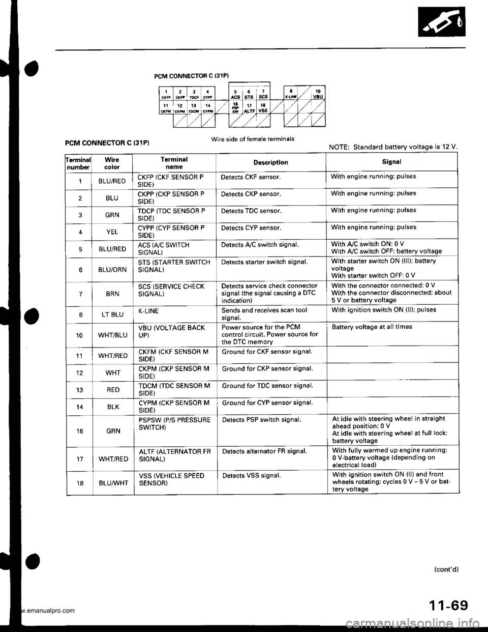
PCM CONNECTOR C (31PI
ferminalnumberWirecolorTerminalnameDoscriptionSignal
'tBLUiREDCKFP (CKF SENSOR PSIDE)Detects CKF sensor.With engine running: pulses
2BLUCKPP (CKP SENSOR PSIDE)Detects CKP sensor.With engine running: pulses
3GRNTDCP (TDC SENSOR PSIDE)Detects TDC sensor.With engine running: pulses
4YELCYPP (CYP SENSOR PSIDE)Detects cYP sensor.With engine running: pulses
5BLU,frEDACS (A/C SWTTCHSIGNAL)Detects A,/C switch signal.With AJC switch ON: 0 VWith A,/C switch OFF: battery voltage
BLU/ORNSTS (STARTER SWITCHSIGNAL)
Detects starter switch signal.With starter switch ON (lll): bafteryvoltageWith staner switch OFF: 0 V
7BRNSCS (SERVICE CHECKSIGNAL)
Detects service check connectorsignal (the signal causing a DTCindication)
With the connector connected: 0 V
With the connector disconnected: about
5 V or battery voltage
8LT BLUK-LINESends and receives scan toolsrgnal.With ignition switch ON (ll): pulses
10WHT/BLUVBUUP)
(VOLTAGE BACKPower source tor the PCMcontrol circuit. Power source for
the DTC memory
Battery voltage at all times
11WHT/REDCKFM (CKF SENSOR MSIDE)Ground for CKF sensor signal.
12WHTCKPM (CKP SENSOR I\4SIDE)Ground lor CKP sensor signal.
13REDTDCM (TDC SENSOR MSIDE}Ground for TDC sensor signal.
14BLKCYPM (CKP SENSOR MSIDE}Ground for CYP sensor signal.
16GRN
PSPSW (P/S PRESSUREswtTcH)Detects PSP switch signal.At idle with steering wheel in straightahead position:0 VAt idle with steering wheel at full lock:
battery voltage
17WHT/REDALTF (ALTERNATOR FRSIGNAL)
Detects alternator FR signal.With fully warmed up engine running:
0 V-battery voltage {depending onelectrical load)
18BLUA/VHTVSS (VEHICLE SPEEDSENSOR)Detects VSS signal.Wirh ignition switch ON (ll) and frontwheels rotating: cycles 0 V - 5 V or bat-tery voltage
Wire side of femaie terminalsPCM CONNECTOR C {31PINOTE: Standard battery voltage is 12 V.
(cont'd)
www.emanualpro.com
Page 275 of 1395
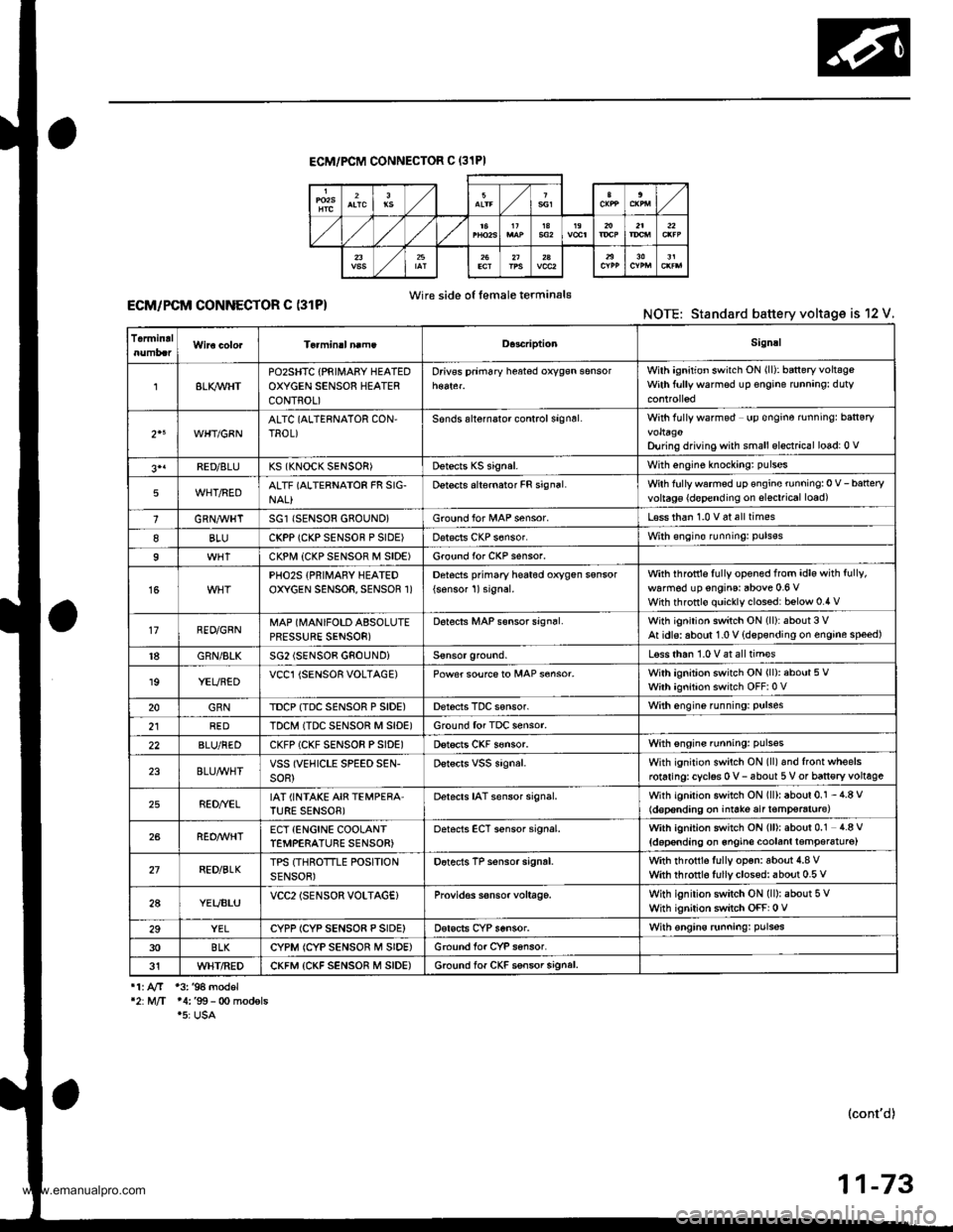
ECM/PCM CONNECTOF C (31PI
Wire side o{ female terminal€ECM/PCM CONNECTOR C (31P)NOTE: Standard battery voltage is 12 V.
TermidalD.3criptionSignal
8LI(WHTPOzSHTC {PRIII4ABY HEATEDOXYGEN SENSOR HEATERCONTROL)
Drivss prim6ry h$ted oxygsn sensorWilh ignition switch ON (ll): baneryvoltsgeWith ftrllywarmsd up €ngine runnang: duty
2"WHT/GBNALTC (ALTERNATOR CON,TROL)Sonds alternalor control signsl.With fully wafmod up €ngine rnningr ban€ryvoltagoDu ng driving with small elsctrical lo6d: 0 v
3'1FED/8LUKS (KNOCK SENSOR)Dstects KS signal.With engine knockang: pulses
5WHT/REDALTF (ALTERNATOR FR SIG-NAL}Detects alternator FR signal.Wth fullywarmed up €ngine running:0 V-batteryvoltag€ {d€pending on slsctrical load)
1GRN,4trHTSG1 (SENSOR 680UND}Ground for l/tAP sensor.L€ss than 1.0 v 6t all times
8BLUCKPP (CKP SENSOF P SIDE)Dat€cls CKP s6nsor.With €ngin€ runningr puls€s
9CKPI.,I| {CKP SENSOF M SIDE)Ground for CKP s€nsor.
15PHO2S {PRIMARY HEATEDOXYGEN SENSOR, SENSOR 1)Detocts pfimary he6t6d oxygen ssnsor
{sonsor 1)signal.with ihfottls fully opened from idle with fully,
walm6d up engins: above 0.6 VWith throttlo quickly clossd: below 0.4 v
17RED/GRNMAP (MANIFOLD ABSOLUTEPRESSURE SENSOR)
D6tects MAP s€nsor sign6l.With ignition switch ON (ll):about 3 VAt idls: aboul 1.0 V {dspsnding on engine speed)
18GRN/BLKSG2 (SENSOB GNOUNDiLsss than 1.0 V at all tim€s
19YEUBEDVCCl {SENSOR VOLTAGE)Power soufce to MAP s€nsor.With ignition switch ON (ll): about 5 VWith ignition switch OFF:0 V
20GRNTDCP {TDC SENSOR P SIDE)Derecis TDC sensor.With engine funning: Pulses
2lREDTDCM ITDC SENSOR M SID€)Ground for TDC sensor.
22BLU/REDCKFP (CKF SENSOR PSIDE)Dstscts CKF s€nsor.With sngins running: pulsss
23BLU/WHTVSS (VEHICLE SPEED SEN-soR)Dstscrs vss signal.With ignition switch ON (ll)and front wheelsrotaringrcyclss 0 v- 6bout 5 V or ban€ry voltage
25RED//ELIAT (INTAKE AIR TEMPERA'TURE SENSOB)Detacts IAT sensor signal.With igniiion switch ON (ll): about 0.1 - 4.8 V(d€p€nding on iniate air t€mp€raturc)
26REO/WHTECT {ENCINE COOLANTTEMPERATURE SENSOR)oetscts ECT sensor signal.With ignition switch ON (ll): about 0.1 4.8 V
{doponding on 6ngin€ coolanl lemper6tu16)
27RED/BLKTPS (THROTTLE POSITIONSENSOR)Dotects TP sensor signrl.with rhrottls fully op€n: aboui 4.8 vwith throtrl6 fullyclosed: about 0.5 v
2AYEUBLUVCC2lSENSOR VOLTAG€}Provid€s s€nsor voltage.With ignilion switch ON (ll): about 5 VWhh ignition switch OFF: 0 V
29YELCYPP ICYP SENSO8 P SIDE)Dsrscts CYP sensor.With €ngins runningr pulsss
30BLKCYPM (CYP SENSOR M SIDE)Ground for CYP sansor.
31WHT/REDCKFM {CKF SENSOR M SIDE)6.ound lof CKF ssnsor signal.
11. AfT 13. '94 model'2:M/T 14:'99- 0o modsls.5: USA
(cont'd)
11-73
www.emanualpro.com
Page 282 of 1395

PGM-FI System
System Description
INPUTS
CKP/TDC/CYP Sensor
CKF Sensor
MAP Sensor
ECT Sensor
IAT Sensor
TP Sensor
Primary HO2S
Secondary H02S
vss
KS*5
BARO Sensor
ELD*6
Starter Signal
ALT FR Signal
Air Conditioning Signal
Ay'T Gear Position Signal*1
Baftery Voltage (lGN.1)
Brake Switch Signal
PSP Switch Signal
Fuel Tank Pressuae Sensor*4. *5
Countershaft Speed Sensor*1
Mainshaft Speed Sensor*r
OVER-DRIVE Switch Signal*s
ENGINE CONTROL MODULE (ECM)/
POWERTRAIN CONTROL MODULE (PCM) OUTPUTS
|iuel 1"j""- Th,rhg ""d Drrafr";-l
Et*-.nt"tdt"cont.orl
to,r*,c;;trffi;]
l.----.---:. .Lrgnrnon |lmrng Lonrror I
Ecir/PcM B*k',p Fr""il]
m;"t-ll-r*'io*l
Fuel Injectors
PGM-Fl Main Relay (Fuel Pump)
MIL
IAC Valve
Ay'C Compressor Clutch Relay
Radiator Fan Relay
Condenser Fan Relay
ALT
tcM
EVAP Purge Control Solenoid
Valve
Primary HO2S Heater
Secondary H02S HeaterEVAP Bypass Solenoid Valve*a *5
EVAP Control Canister Vent Shut
DLC
Lock-up Control Solenoid Valve*l
Shift Control Solenoid Valve*1
Ay'T Clutch Pressure Control
Solenoid Valve*1
D4 Indicator Light'1 *3, *a
D Indicator Light,l *5
OVER-DRIVE OFF Indicator
Lighl*t *:
*1: A/T {3:'97 model'2: M/f +4:'98 model*5: '99 - 00 models"6: USA
PGM-Fl System
The PGM-Fl system on this model is a sequential multiport fuel injection system.
Fuel iniecior Timing and Duration
The ECM/PCM contains memories for the basic discharge durations at various engine speeds and manifold pressure. The
basic discharge duration, after being read out from the memory, is further modified by signals sent from various sensors
to obtain the final discharge duration.
ldle Air Control
ldle Air Control Valve (lAC Valve)
When the engine is cold, the Ay'C compressor is on, the transmission is in gear, the brake pedal is depressed, the P/S load
is high, or the alternator is charging, the ECM/PCM controls current to the IAC Valve to maintain the correct idle speed.
lgnition Timing Control
o The ECM/PCM contains memories for basic ionition timing at various engine speeds and manifold air flow rates.
lgnition timing is also adjusted for engine coolant temperature.
. A knock control system was adopted which sets the ideal ig nition timing for the octane rating of the gasoline used.*s
Other Control Funstions
1. Starting Control
When the engine is started. the ECM/PCM provides a rich mixture by increasing fuel injector duration.
2. Fuel Pump Control
. When the ignition switch is initially turned on (ll). the ECMiPCM suppli€s ground to the PGM-FI main relay that
supplies current to the fuel pump for two seconds to pressurize the fuel system.
. When the engine is running, the ECM/PCM supplies ground to the PGM-FI main relay that supplies current to the
fuel oumo.
. When the engine is not running and the ignition is on, the ECM/PCM cuts ground to the PGM-FI main relay which
cuts current to the fuel pump.
1 1-80
www.emanualpro.com
Page 283 of 1395

Fuel Cut-off Control
. During deceleration with the throttle valve closed, current to the fuel injectors iscutoffto improvefuel economyat
speeds over 970 rpm ('97 - 98 models), 920 rpm ('99 - 00 modelsl.
. Fuel cut-off action also takes place when engine speed exceeds 6,500 rpm ('97 - 98 models), 6900 rpm ('99 - 00
models), regardless of the position of the throttle valve, to protect the engine from over-rewing.
With Ay'T model. the PCM cuts the fuel at engine speeds over 5,000 rpm when the vehicle is not moving.*'�
4,./C Comoressor Clutch Relav
When the ECM/PCM receives a demand for cooling from the air conditioning system, it delays the compressor from
being energized, and enriches the mixture to assure a smooth transition to the Ay'C mode.
Evaporative Emission (EVAP) Purge Control Solenoid Valve
When the engine coolant temperature is above 154"F (68'C), the ECM/PCM controls the EVAP purge control solenoid
valve which controls vacuum to the EVAP purge control canister,
Alternator Control
The system controls the voltage generated at the alternator in accordance with the electrical load and driving mode.
which reduces the engine load to improve the fuel economy.
PCM Fail-saf e/Back-up Functions
1. Fail-safe Function
When an abnormality occurs in a signal from a sensor, the ECM/PCM ignores that signal and assumes a pre-pre
grammed value for that sensor that allows the engine to continue to run.
2. Back-up Function
When an abnormality occurs in the ECM/PCM itself, the fuel injectors are controlled by a back-up circuit independent
of the system in order to permit minimal driving.
3. Self-diagnosis Function IMalfunction Indicator Lamp (MlL)l
When an abnormality occurs in a signal from a sensor, the ECM/PCM supplies ground for the MIL and stores the DTC
in erasable memory. When the ignition is initially turned on {ll), the ECM/PCM supplies ground for the MIL for two
seconds to check the MIL bulb condition.
4. Two Trio Detection Method
To prevent false indications, the Two Trip Detection Method is used for the HO2S*1, fuel metering-related. idle control
system, ECT sensor and EVAP control system self-diagnostic functions. When an abnormality occurs, the ECM/PCM
stores it in its memory. When the same abnormality recurs after the ignition switch is turned OFF and ON (ll) again,
the ECM/PCM informs the driver by lighting the MlL. However, to ease troubleshooting, this function is cancelled
when you jump the service check connector, The MIL will then blink immediately when an abnormality occurs.
5. Two (or Three) Driving Cycle Detection Method {'97 model)
A "Driving Cycle" consists of starting the engine, beginning closed loop operation, and stopping the engine. lf misfir-
ing that increases emissions or EVAP control system malfunction is detected during two consecutive driving cycles.
or TWC deterioration is detected during three consecutive driving cycles, the ECM/PCM turns the MIL on. However, to
ease troubleshooting, this function is cancelled when you jump the service check connector. The MIL will then blink
immediately when an abnormality occurs.
*1: '97 - 98 models*2: '99 - 00 models
5.
www.emanualpro.com
Page 325 of 1395
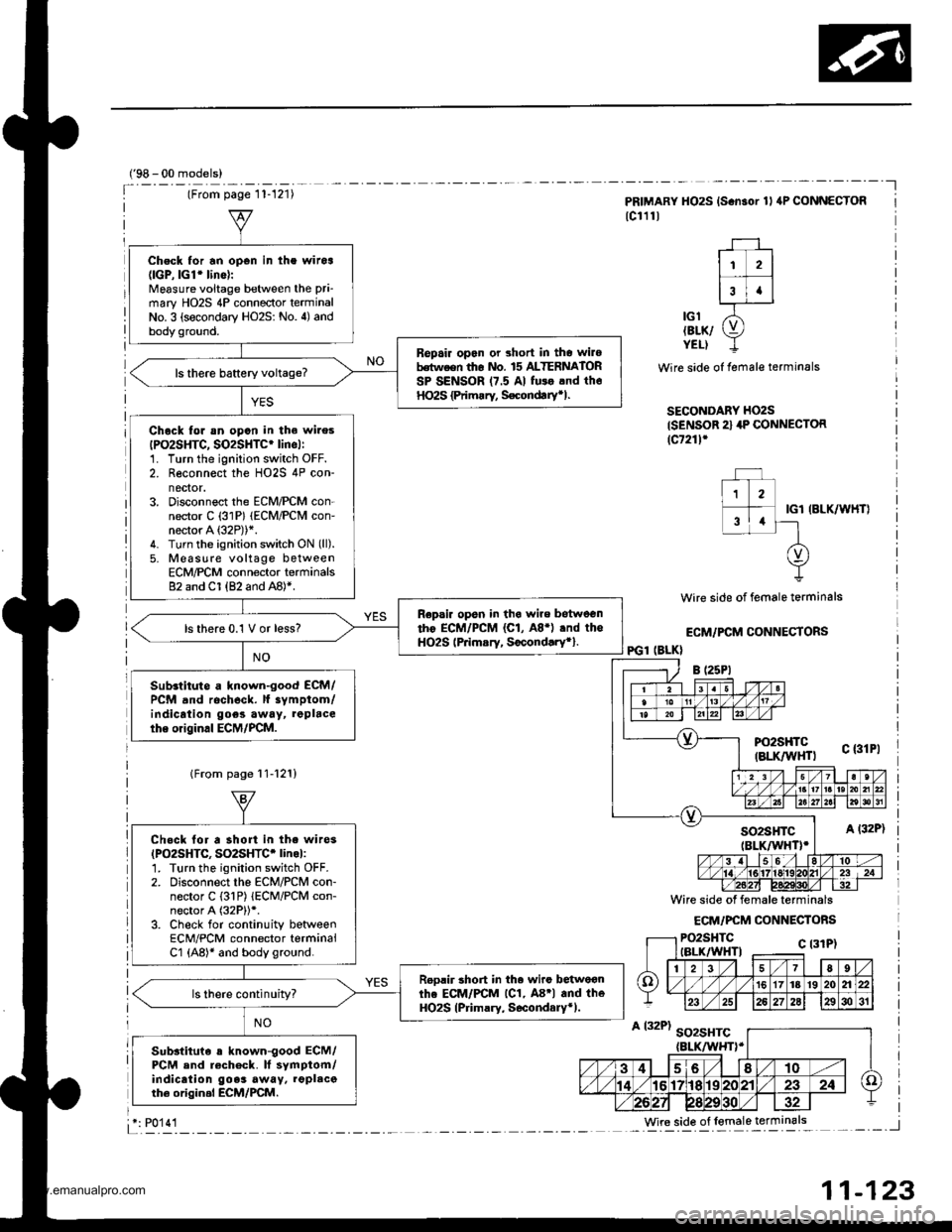
Check for an open in the witoa(lGP,lGl'lino):
Mgasure voitage between the pri-
mary HO2S 4P connector terminalNo. 3 (secondary HO2S: No. 4) andbody ground.
Bepair opan or short in tho wilobdtween th6 nlo. 15 ALTERNATORSP SENSOR 17.5 Al fu$ .nd th6HO2S {Primrry, S€condtrytl.
Chock lor sn opon in the wires
IPO2SHTC, SO2SHTC' lincl:1. Turn the ignition switch OFF.2. Reconnect the HO2S 4P con-nector.3. Disconnect the ECM/PCM con-nector C (31P) (ECM/PCM con-neaor A (32P))*.
4. Turn the ignition switch ON (ll).
5. Moasure voltage betweenECM/PCM connector terminals82 and Cl (82 and A8)*.
Repsir opsn in tha wire betweentho ECM/PCM (C1, A8.) .nd theHO2S lPrimsry, Socond.ry*}.ls there 0.1 V or less?
Sub.titute a known-good ECM/PCM and rocheck. lf iymptom/indicrtion goes away, repbcethe original ECM/PCM.
('98 - 00 models)
Wire side of female terminals
ECM/FCM CONNECTORS
IGl IBLK/WHT}
PRIMARY HO2S {S.n3or 1l aP CONNECTOR
lc111l
11 2l
r--T -l3t.lL-.IJ------J
lcl /5'tErK/ g,YELI I
Wire side of female terminals
SECONDARY HO2S
{SENSOR 2} 4P CONNECTOR(c7211'
PGl (BLK}
lFrom page 11-12'!)
Chock lor a short in the wi.es(PO2SHTC, SO2SHTC' linol:1. Turn the ignition switch OFF.2. Disconnect the EcM/PcM con-nector C {31P) lECM/PCM con-nector A (32P))*.
3. Check for continuity betweenECM/PCM connector terminalCl (A8)* and body ground.
Roolir 3hort in th. wiro betwoonthe ECM/PCM lC1, A8'l and theHO2S (Primary, S6condary*).ls there continuity?
Sub3tituie s known-good ECM/PCM and rech6ck. It symptom/indicaiion goes away. lgplacoth6 origin.l ECM/PCM.
Wire side of lemale terminals: P0'14'l
11-123
www.emanualpro.com
Page 342 of 1395
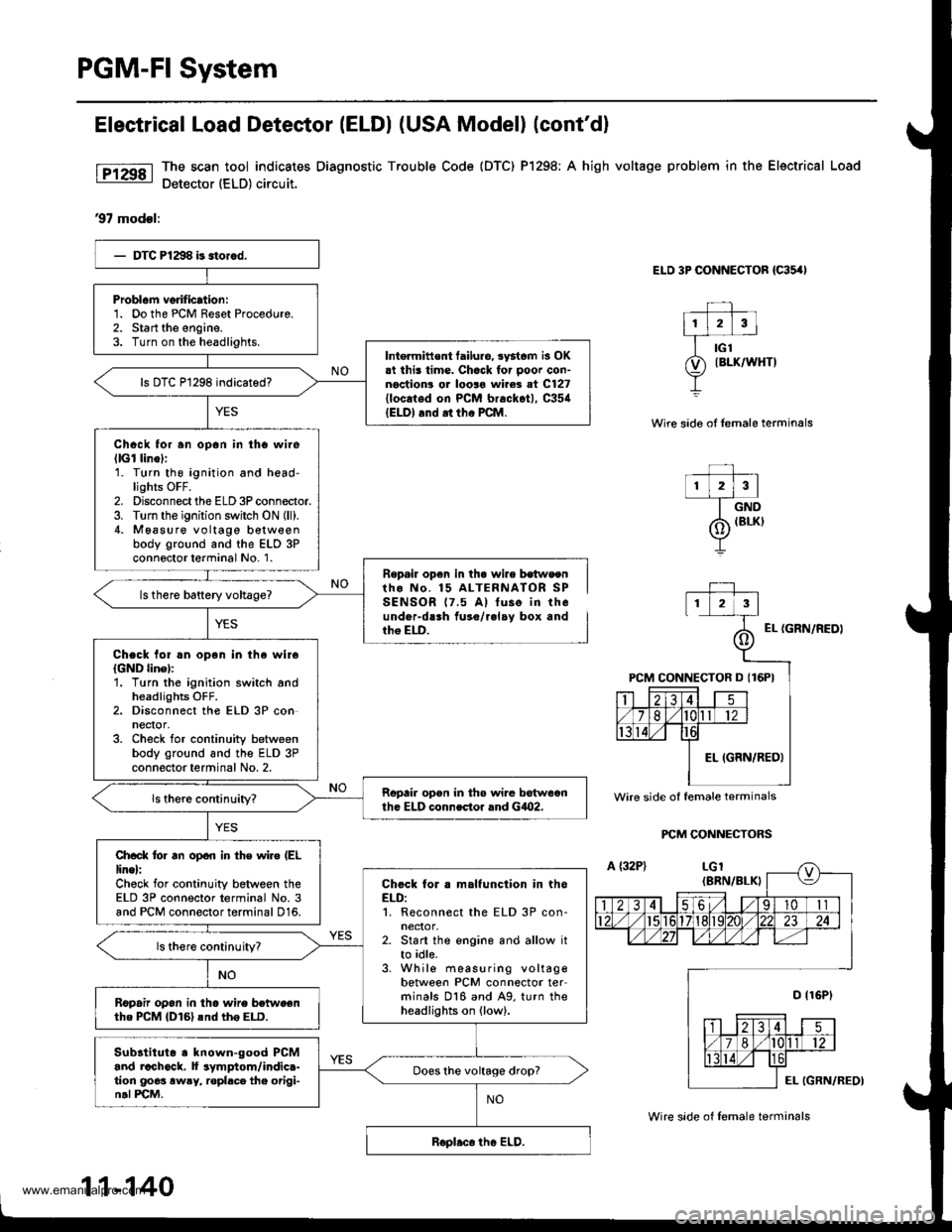
PGM-FI System
Electrical Load Detestor (ELDI (USA Model) (cont'dl
The scan tool indicates Diagnostic Trouble Code {DTC) Pl298; A high voltage problem in the Electrical Load
Detector (ELD) circuit.
97 modsl:
ELD 3P CONNECTOR {C35,'I
Wire sido oI lemale terminals
r lzlrl--T_ow
/6 IBLKI
Y
Repail op€n in th. wire b€tws€ntho No. 15 ALTERNATOR SPSENSOR 17.5 A) tuse in theunder-dlrh fuso/r.lay box andth6 ELD.EL {GRN/NEDI
PCM CONNECTORS
Problam verification:1. Do the PCM Reset Procedure.2. Start the engine.3. Turn on the headlights.Intermittent tailuro, systcm is OK.t this time. Chack for ooor con-noction! or looro wire3 at C127{locaied on PCM brackot), C35{{ELDI and .t tho PCM.
Chack for an opan in tho wilellGl linol:1. Turn thg ignition and head-lights OFF.2. Disconnect the ELD 3P connector.3. Turn the ignition switch ON {ll).4. M6asure voltage b€tw€enbody ground and the ELD 3Pconnoctor terminal No. 1.
Chock lol !n open in the wireIGND linel:'1. Turn the ignition switch andheadlights OFF.2. Disconnect the ELD 3P conneqor,3. Check for continuity betweenbody ground and the ELD 3Pconnector terminal No. 2.
Ropair opon in th6 wi.e betweonth. ELD connector rnd GiO2,
Ch.ck lo. an open in th€ wiro (EL
line):Check for continuity between theELD 3P connector terminal No. 3and PCM connector terminal 016.
Chock for . malfunction in theELD:1. Reconnect the ELD 3P con-neclor,2. Start the engine and allow itto idle.3. While measuring voltagebetween PCM connector terminals 016 and A9. turn theheadlights on (low).
ls there continuityT
R6pafu op6n in tho wire betweenthe PCM {D161snd th6 ELD.
Subltituto . known-good PCMand rachock, f symptom/indic.-tion goes awry, ropl.ce the origi-n.l PCM.
Does the voltage drop?
Wire side of lemale terminals
11-140
Wire side of lemale terminals
www.emanualpro.com