Engine mounting HONDA CR-V 2000 RD1-RD3 / 1.G Owner's Manual
[x] Cancel search | Manufacturer: HONDA, Model Year: 2000, Model line: CR-V, Model: HONDA CR-V 2000 RD1-RD3 / 1.GPages: 1395, PDF Size: 35.62 MB
Page 907 of 1395

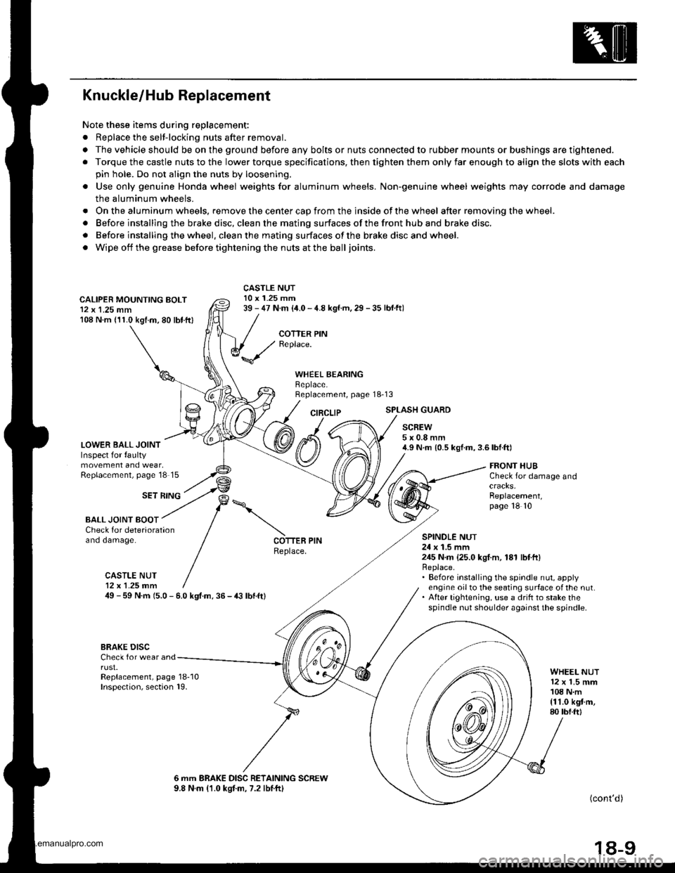
Knuckle/Hub Replacement
Note these items during replacement:
. Replace the selt-locking nuts after removal.
. The vehicle should be on the ground before any bolts or nuts connected to rubber mounts or bushings are tightened.
. Torque the castle nuts to the lower torque specifications, then tighten them only far enough to align the slots with each
pin hole. Do not align the nuts by loosening.
o Use only genuine Honda wheel weights for aluminum wheels. Non'genuine wheel weights may corrode and damage
the aluminum wheels.
. Onthealuminum wheels, remove the center cap from the inside of the wheel after removing the wheel.
. Before installing the brake disc, clean the mating surfaces of the front hub and brake disc.
. Before installing the wheel. clean the mating surfaces ofthe brake disc and wheel.
. Wipe off the grease before tightening the nuts at the balljoints.
CALIPER MOUNTING BOLT12 x 1.25 mm108 N.m (11.0 kgtm.80 lbt.ftl
LOWER BALL JOINTInspect for faultymovement and wear,Replacement, page'18 15
CASTLE NUT10 x 1.25 mm39 - 47 N.m (i1.0 - 4.8 kgf.m, 29 - 35 lbf.ftl
COTTER PINReplace.
WHEEL BEARINGBeplace.Replacement, page 18-13
CIRCLIPSPLASH GUARD
SCREW5x0.8mm4.9 N.m {0.5 kgf.m,3.6lbf.ft)
SET RING
FRONT HUBCheck for damage and
Replacement,page 18 10
BALL JOINT BOOTCheck for deteriorationano oamage.SPINOLE NUT24 x 1.5 mm245 N.m {25.0 kgI.m, 181 lbtft}Replace.. Before installing the spindle nut, applyengine oil to the seating surface of the nut.. After tightening, use a drift to stake thespindle nut shoulder against the spindle.
COTTER PINReplace.
CASTLE NUT12x 1.25 fim49 - 59 N.m 15.0 - 6.0 kgt.m. 36 - € lbf.ft)
BRAKE DISCCheck for wear andrust.Replacement, page 18-10Inspection, section 19.
WHEEL NUT12 x 1.5 mm108 N.m{11.0 kgt m,80 tbf.ftl
6 mm BRAKE DISC RETAINING SCREW9.8 N.m (1.0 kgtm, 7.2 lbtftl(cont'd )
18-9
www.emanualpro.com
Page 1141 of 1395

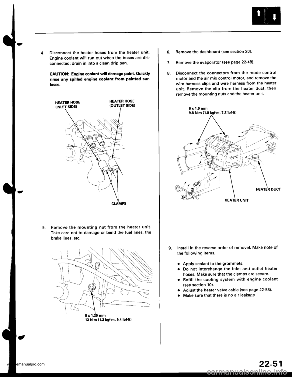
4. Disconnect the heater hoses from the heater unit.
Engine coolant will run out when the hoses are dis-
connected; drain in into a clean drip pan.
CAUTION: Engino coolant will damage p8int. Ouickly
rinse any spill€d engine coolant Itom painted sur-
faces.
HEATER HOSEIOUTLET SIDE)
Remove the mounting nut from the heater unit.
Take care not to damage or bend the fuel lines, the
brake lines. etc.
CLAMPS
13 N.m 11.3 kg{.m,9.4 lbtftl
22-51
7.
ll.
Remove the dashboard (see section 20).
Remove the evaporator (see page 22-48).
Disconnect the connectors from the mode control
motor and the air mix control motor, and remove the
wire harness clips and wire harness from the heater
unit. Remove the clip from the heater duct, then
remove the mounting nuts and the heater unit
6x1.0mm9,8 N.m (1.0 kgt m,7.2lblft)
qInstall in the reverse order of removal. Make note of
the following items.
a
a
a
a
Apply sealant to the grommets.
Do not interchange the inlet and outlet heater
hoses. Make sure that the clamps are secure.
Refill the cooling system with engine coolant
{see section 10).
Adiust the heater valve cable (see page 22-53).
Make sure that there is no air leakage.
HEATER UNIT
www.emanualpro.com
Page 1152 of 1395

Compressor
Replacement
lf the compressor is marginally operable. run the
engine at idie speed, and let the air conditioner
work for a few minutes. then shut the engine off.
Disconnect the negative cable from the battery.
Recover the refrigerant with a recovery/recycling/
charging station (see page 22-59).
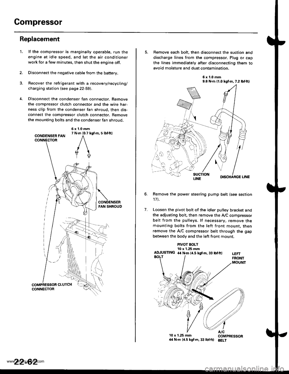
Disconnect the condenser fan connector. Remove
the compressor clutch connector and the wire har-
ness clip from the condenser fan shroud, then dis-
connect the compressor clutch connector. Remove
the mounting bolts and the condenser fan shroud,
CONDENSER FANCONNECTOR
6x1.0mm7 N.m 10.7 kg{.m, 5 lbl.ftl
'L
2.
5. Remove each bolt, then disconnect the suction and
discharge lines from the compressor. Plug or cap
the lines immediately after disconnecting them to
avoid moisture and dust contamination,
6x1.0mm9.8 N.m 11.0 kgf.m,7.2 lbf.ft)
DISCHARGE LINE
Remove the power steering pump belt (see section
17t.
Loosen the pivot bolt of the idler pulley bracket and
the adiusting bolt, then remove the Ay'C compressor
belt from the pulleys. lf necessary, remove themounting bolts from the left front mount, thenremove the A,/C compressor belt through the gap
between the bodv and the left front mount.
6.
7.
PIVOT BOLT10 x 1.25 mmAIUUSTING 4,t N.m (4.5 kgf.m, 33 tbf.ftlt€FTFRONTMOUltlT
10x 1.25 mm COMPRESSOR/t4 N.m (4.5 kgl.m,33 lbtftl BELI
LINE
www.emanualpro.com