Pulsers/Wheel Sensors
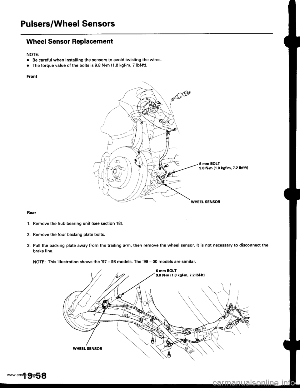
Wheel Sensor Replacement
NOTE;
. Be carefulwhen installing the sensors to avoid twisting the wires.
. The torque value of the bolts is 9.8 N.m ( 1.0 kgf.m, 7 Ibf.ft).
Front
6 mm BOLT9.8 N.m {1.0 kgtm. ?.2lbf'ft)
WHEEL SENSOR
Rgar
1. Remove the hub bearing unit (see section 18).
2. Remove the tour backing plate bolts.
3, Pull the backing plate away from the trailing arm, then remove the wheel sensor. lt is not necessary to disconnect the
brake line.
NOTE: This illustration shows the '97 - 98 models, The '99 - 00 models are similar.
6 mm BOLT9,8 N.m 11.0 kgf.m, 7.2lbf.ft)
\all
19-58
WHEEL SENSOR
www.emanualpro.com
a
Heater and Air Conditioning
Heater ...........21
NOTE: Section 21 ("Heater") is included in section 22.
Air Conditioning ......'..'.. '.'22'1
SUPPLEMENTAL RESTRAINT SYSTEM (SRS}
This model has an SRS which includes a driver's airbag in the steering wheel hub, a passenger's airbag in the dashboard
above the glove box ('97,00 models). and seat belt tensioners in the seat belt retractors ('98 - 00 models). Information
necessary to safely service the SRS is included in this Service Manual. ltems marked with an asterisk (*) on the contents
page include. or are located near, SRS components. Servicing, disassembling or replacing these items will require special
precautions and tools, and should only be done by an authorized Honda dealer.
@. To avoid rendering the SRS inoperative, which could lead to personal iniury or death in the event of 8 severe frontal
collision, all SRS service work must be performed by an authotized Honda dealer.
lmproper service procedures, including incorrect removal and installation of the SRS, could lead to personal iniury
caused by unintentional deployment of the airbags ('97 - 00 models), and seat belt tensioners 138 - 00 models).
Do not bump the SRS unit. Otherwise, the system may fail in case of a collision, or the airbags may deploy when the
ignition switch is ON {lll.
SRS eleqtrical wiring harnesses are identified by yellow color coding. Related components are located in the steering
column, front console, dashboard, dashboard lower panel, and in the dashboard above the glove box. Do not use elec-
tricaltest equipment on thes€ cilcuils.
www.emanualpro.com
Gable Reel
Replacement (cont'dl
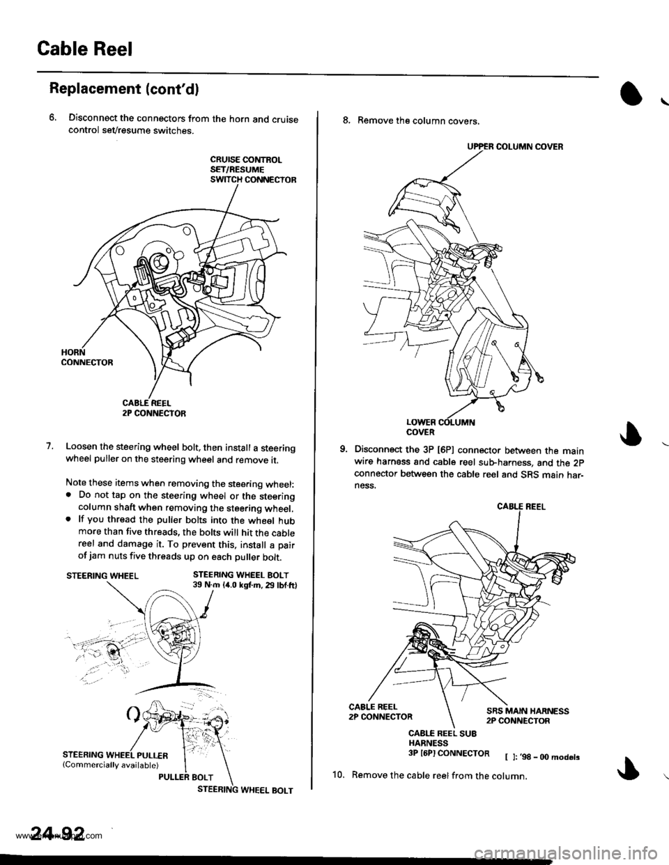
6, Disconnect the connectors from the horn and cruisecontrol sevresume switches.
cRursE coNtRoLSET/RESUMESWITCH CONNECTOR
1.Loosen the steering wheel bolt, then install a steeringwheel puller on the steering wheel and remove it.
Note these items when removing the stee.ing wheel:. Do not tap on the steering wheel or the steeringcolumn shaft when removing the steering wheel,. lf you thread the puller bolts into the wheel hubmore than five threads, the bolts will hit the cablereel and damage it. To prevent this. install a pair
of jam nuts five threads up on each puller bolt.
STEERING WHEEL BOLT39 N.m 14.0 kgf.m. 29 lbf.ftlSTEERING WHEEL
STEERING
2P CONNECTOR
24-92
8. Remove the column covers,
Disconnect the 3P [6P] connector between the mainwire harness and cable reel sub-harness, and the 2pconnector between the cable reel and SRS main har-ness.
CAALE REEL SU8HARNESS3P l6Pl CONNECTOR [ ]:,98_00modets
10. Remove the cable reelfrom the cotumn,
COVER
www.emanualpro.com


