Cat HONDA CR-V 2000 RD1-RD3 / 1.G Workshop Manual
[x] Cancel search | Manufacturer: HONDA, Model Year: 2000, Model line: CR-V, Model: HONDA CR-V 2000 RD1-RD3 / 1.GPages: 1395, PDF Size: 35.62 MB
Page 1032 of 1395
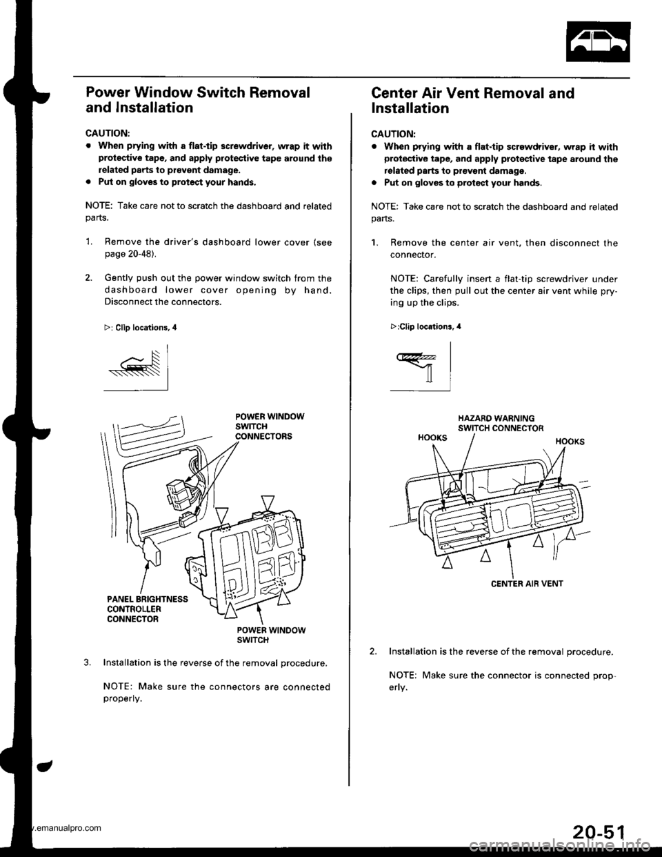
Power Window Switch Removal
and Installation
CAUTION:
. When prying with a flat.tip screwdriver, wrap it withprotective tape, and apply protective tape around th€
related parts to ptavgnt damage.
. Put on gloves to protect your hands.
NOTE: Take care not to scratch the dashboard and relatedparts.
'L Remove the driver's dashboard lower cover (see
page 20-48).
2. Gently push out the power window switch from the
dashboard lower cover opening by hand.
Disconnect the connectors.
>: Clip locations, 4
POWER WTNOOWSWITCH
Installation is the reverse of the removal procedure,
NOTE: Make sure the connectors are connectedproperly.
Center Air Vent Removal and
Installation
CAUTION:
. When prying with a flat.tip screwdriver, wrap h withprotective tape, and apply proteqtive tape around the
rolated parts to prevont damage.
. Put on gloves to protect your hands.
NOTE: Take care not to scratch the dashboard and related
pans.
1. Remove the center air vent. then disconnect the
connector.
NOTE: Carefullv insen a flat-tio screwdriver under
the clips, then pull out the center air vent while pry-
ing up the clips.
Installation is the reverse of the removal procedure.
NOTE; Make sure the connector is connected prop-
>:Clip locations.,l
I
ffil
CENTER AIB VENT
20-51
www.emanualpro.com
Page 1033 of 1395
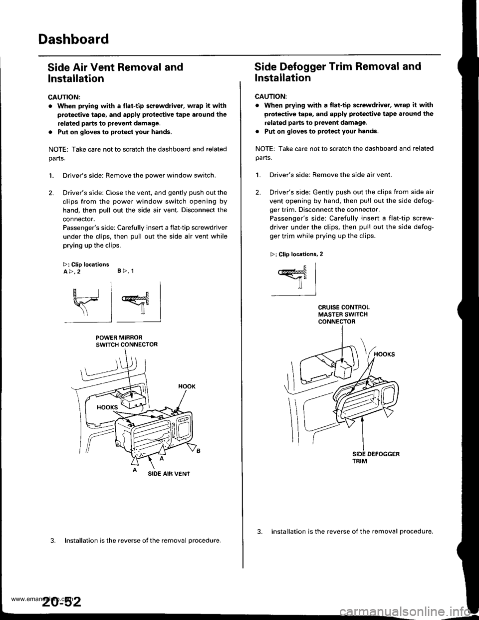
Dashboard
Side Air Vent Removal and
lnstallation
CAUTION:
. When prying with a flat-tip screwdriver, wrap it with
protec'tive tape, and apply protcctive tape around the
related parts to provent damage.
. Put on glov€s to protect your hands.
NOTE: Take care not to scratch the dashboard and related
parts.
1. Driver's side: Remove the Dower window switch.
2. Driver's side: Close the vent, and gently push out the
clips from the power window switch opening by
hand, then pull out the side air vent. Disconnect the
connector.
Passenger's side: Carefully insert a flat-tip screwdriver
under the clips. then pull out the side air vent while
prying up the clips.
>: Clip locationsA>,2 B>, 1
sl 4
POWER MIRRORSWITCH CONNECTOR
SIDE AIB VENT
3. Installation is the reverse ofthe removal procedure.
20-52
3. Installation is the reverse of the removal procedure.
Side Defogger Trim Removal and
lnstallation
CAUTION:
. when prying whh a flat-tip sctewdriver, wrap it with
protective tape, and apply protectiv€ tape around the
relatgd parts to prevent damagg.
. Put on gloves to protect your hands.
NOTE: Take care not to scratch the dashboard and related
oa rts.
1. Driver's side: Remove the side air vent.
2. Driver's side: Gently push out the clips from side air
vent opening by hand, then pull out the side defog-
ger trim. Disconnect the connector.
Passenger's side: Carefully insert a flat-tip screw-
driver under the clips, then pull out the side defog-
ger trim while prying up the clips.
>: Clip locations, 2
c1
ffil-t
TRIM
www.emanualpro.com
Page 1034 of 1395
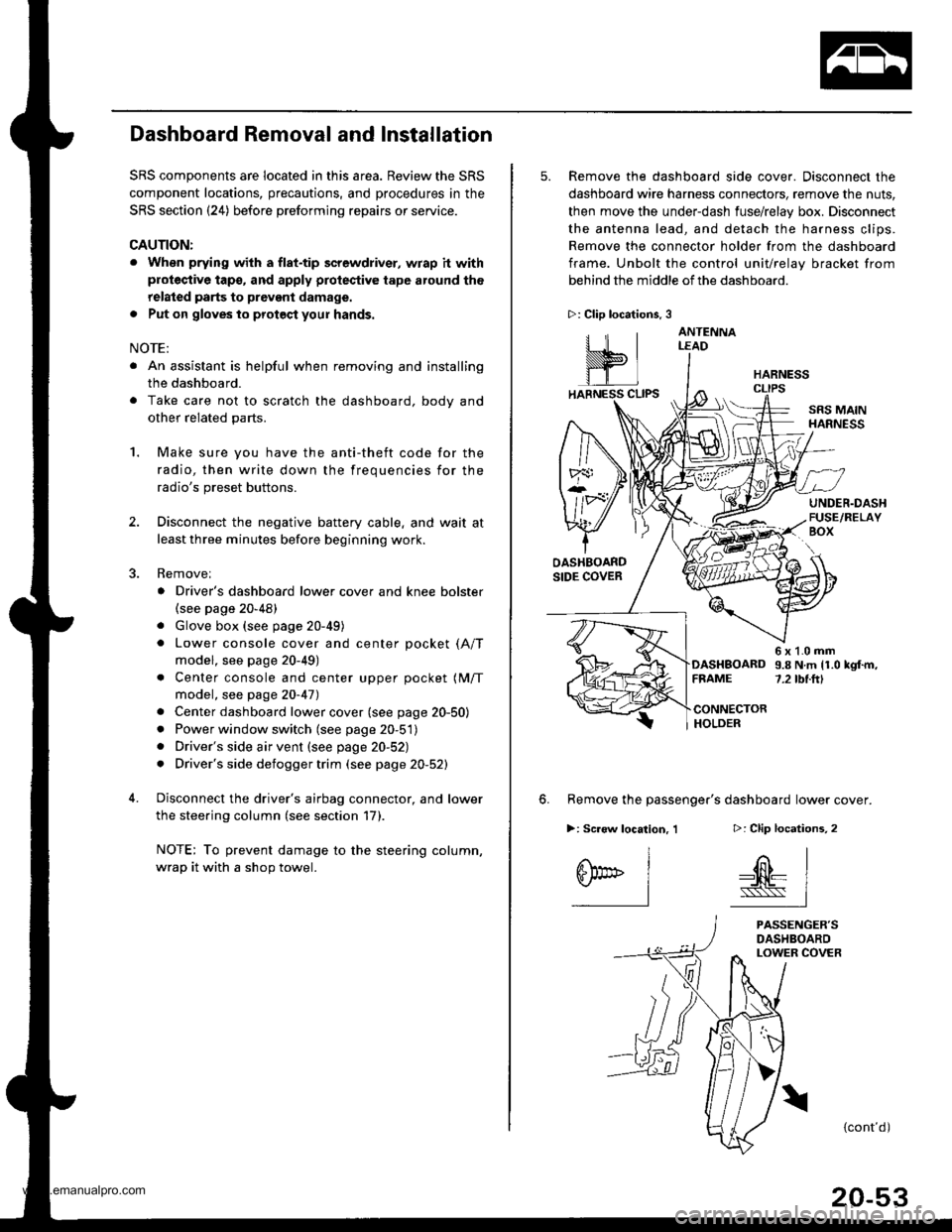
Dashboard Removal and Installation
SRS components are located in this area. Review the SRS
component locations, precautions, and procedures in the
SRS section {24) before preforming repairs or service.
CAUTION:
. When prying with a flat-tip screwdriver, wrap h withprotective tap€, and apply protective tape around the
related parts to prevgnt damage.
. Put on gloves to prot€ct your hands.
NOTE:
. An assistant is helpful when removing and installing
the dashboard.
. Take care not to scratch the dashboard, bodv and
other related parts.
1.Make sure you have the anti-theft code for the
radio, then write down the frequencies for the
radio's preset buttons.
Disconnect the negative battery cable. and wait at
least three minutes before beginning work.
Removei
a Driver's dashboard lower cover and knee bolster(see page 20-48)
. Glove box (see page 20-49)
. Lower console cover and center pocket (A/T
model, see page 20-49)
. Center console and center upper pocket (M/T
model, see page 20-47)
. Center dashboard lower cover (see page 20-50)
. Power window switch (see page 20-51)
. Driver's side air vent (see page 20-52)
. Driver's side defogger trim (see page 20-52)
Disconnect the driver's airbag connector, and lower
the steering column (see section 17)
NOTE: To prevent damage to the steering column,
wrap it with a shop towel.
2.
5. Remove the dashboard side cover. Disconnect the
dashboard wire harness connectors, remove the nuts,
then move the under-dash fuse/relay box. Disconnect
the antenna lead, and detach the harness clips.
Remove the connector holder from the dashboard
frame. Unbolt the control unit/relay bracket from
behind the middle of the dashboard.
HARNESS
6. Remove the passenger's dashboard lower cover.
D: Clip locations,
nl
-$t- Issj
I
ANTENNALEAD
>: Clip locations.
rttl
slllll
>: Scr€w location, 1
I
SF:oo I-l
SRS MAINHARNESS
UNDER.DASHFUSE/RELAYBOX
OASHBOARDSIDE COVER
6x1.0mm9.8Nm11.0kgf.m,7.2tbt.ftlDASHBOARDFFAME
CONNECTORHOLDER
PASSENGER'SDASHBOARDLOWER COVER
{cont'd)
www.emanualpro.com
Page 1036 of 1395
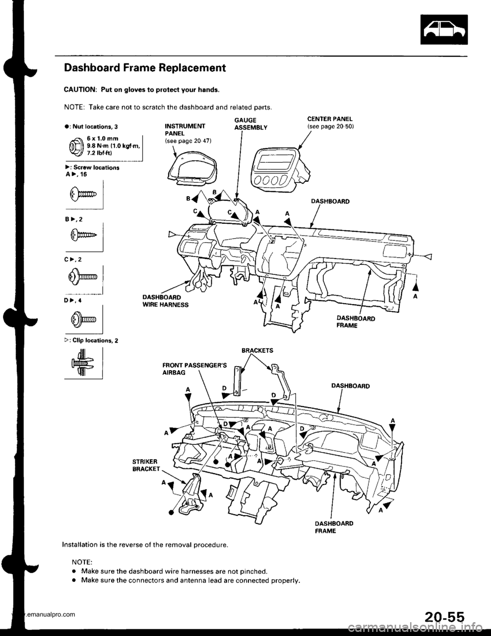
Dashboard Frame Replacement
CAUTION: Put on gloves to prolect your hands.
NOTE: Take care not to scratch the dashboard and related parts.
GAUGEa: Nut locations,3INSTRUMENTPANEL(see page 20 47)
\,.\
/ ,.-------f,\
lu /A
w
CENTER PANEL{see page 20 50)
6x1.0mm9.8 N.rn 11.0 kgf.m,7.2 tbt.ftl
>i Screw locationsA>,16
I
\,r*
B>,2
^l
S@t' 1-l
c >,2
I
0@l"l
D>.a
^l
0Fl-l
>: Clip localions.2
.dr IIhll'rifi- |-wr
i
DASHBOARDFRAME
DASHBOARDwlRE HARNESS
Installation is the reverse oI the removal orocedure.
NOTE:
. Make sure the dashboard wire harnesses are not Dinched.. Make sure the connectors and antenna lead are connected properly.
FRONT PASSENGER'S
www.emanualpro.com
Page 1037 of 1395
Seats
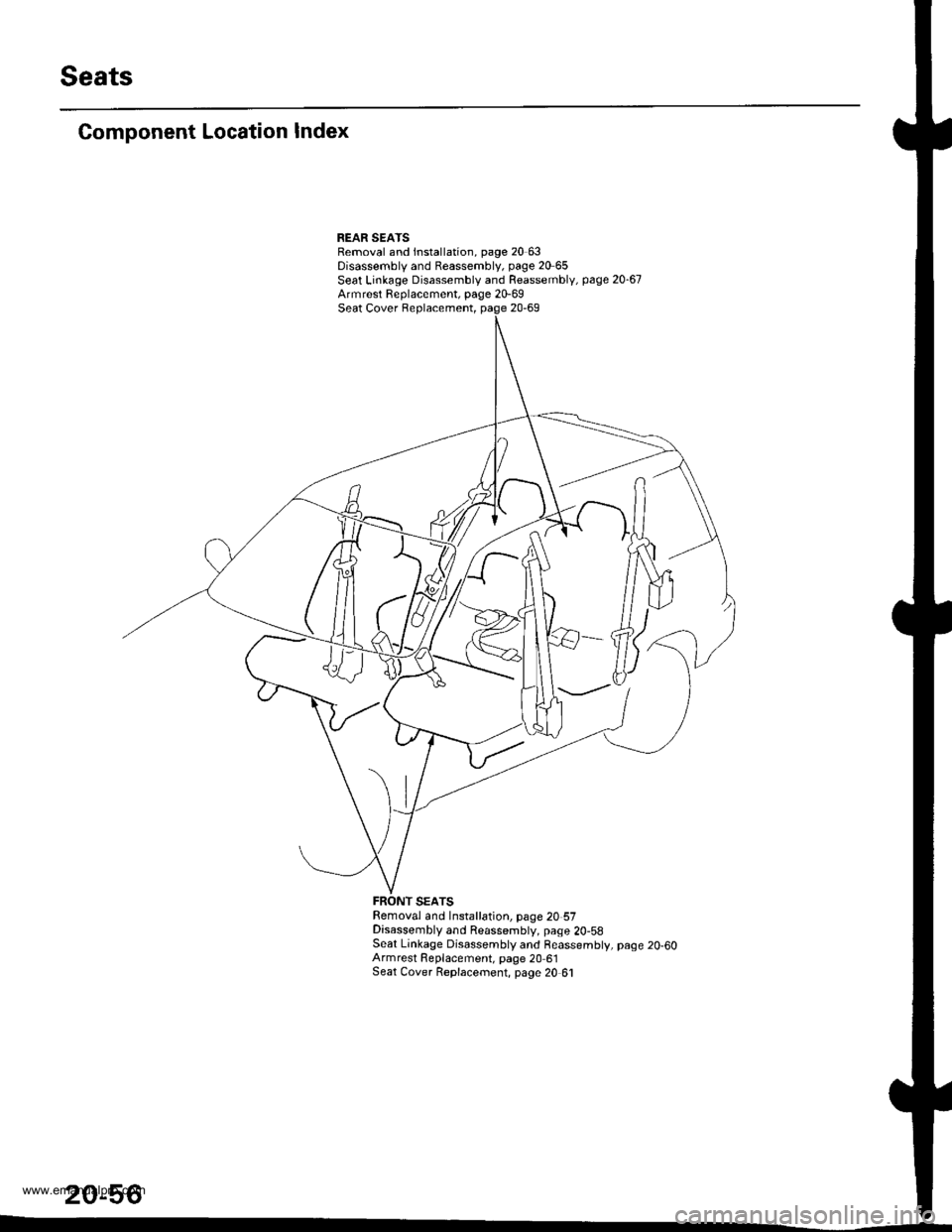
Component Location Index
REAR SEAISRemoval and lnstallation, page 20 63Disassembly and Reassembly, page 20 65Seat Linkage Disassembly and Reassembly, page 20-67Armrest Replacement, page 20-69Seat Cover Replacement, page 20-69
Removal and Installation, page 20 57Disassembly and Reassembly, page 2O-58Seat Linkage Disassembly and Reassembly, page 20-60Armrest Fleplacement, page 20 61Seat Cover Replacernent, page 20 61
20-56
www.emanualpro.com
Page 1039 of 1395
Seats
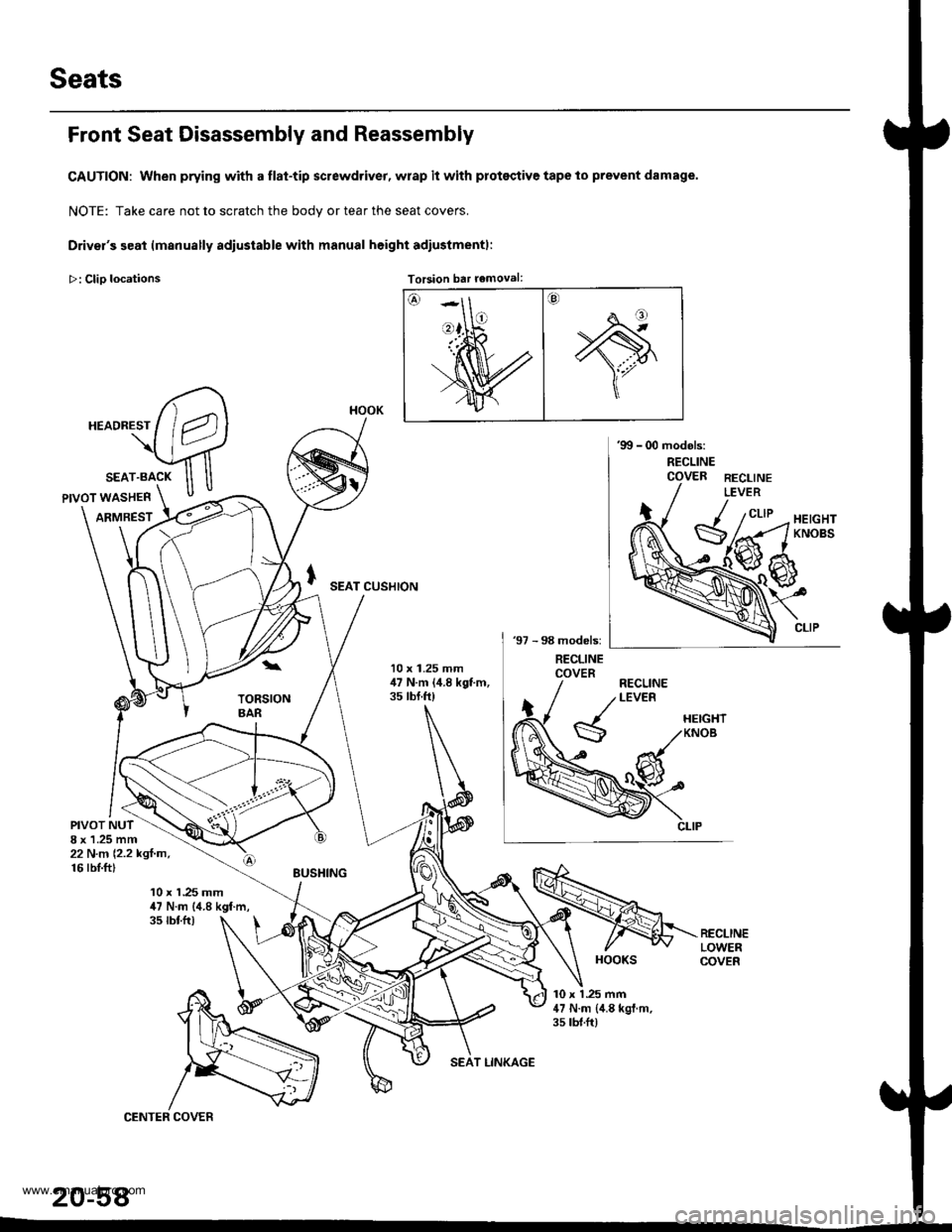
Front Seat Disassembly and Reassembly
CAUTION: When prying with a flat-tip screwdriver, wrap it with protsqtive tape to prevent damage.
NOTE: Take care not to scratch the bodv or tear the seat covers.
Driver's seat lmanually adiustable with manual height adiustmentl:
>: Clio locations Torsion bar removal:Torsion bar removal:
SEAT CUSHION
10 x 1.25 mm,17 N.m (,1.8 kgt m,35 tbt.ft)
PIVOT NUT8 x 1.25 mm22 N.n 12.2 kgl.m,16 rbI.ft)
10 x 1.25 mm47 N.m (4.8 kgf.m,35 tbtfr)
10 x 1 .25 mm47 N.m {,1.8 kgl.m.35 rbt.ft)
20-58
HOOK
HOOKS
www.emanualpro.com
Page 1040 of 1395
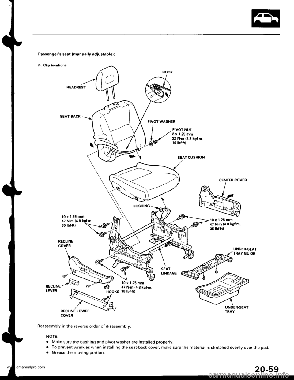
Passenger's seat (manually adiustablel:
>: Clip locations
HEADREST
SEAT.BACK
10 x 1.25 mm
PIVOT WASHER
PIVOT NUT8 x 1.25 mm22 N.m 12.2 kgl..n,16 tbt.ftl
SEAT CUSHION
CENTER COVER
BUSHING
COVER
Reassembly in the reverse order of disassembly.
NOTE:
. Make sure the bushing and pivot washer are installed properly.
. To prevent wrinkles when installing the seat-back cover, make sure the. Grease the moving portion.
'10 x 1.25 mm47 N.m {4.8 kgf m,
35 rbl.ft)
UNDER-SEATTRAY GUIDE
,U N.m 14.835 rbt.ft)
dHOOKS
10 x 1.25 mm17 N.m {4.8 kgl.m,35 tbf.ft)
HOOK
material is stretched evenly over the pad.
www.emanualpro.com
Page 1042 of 1395
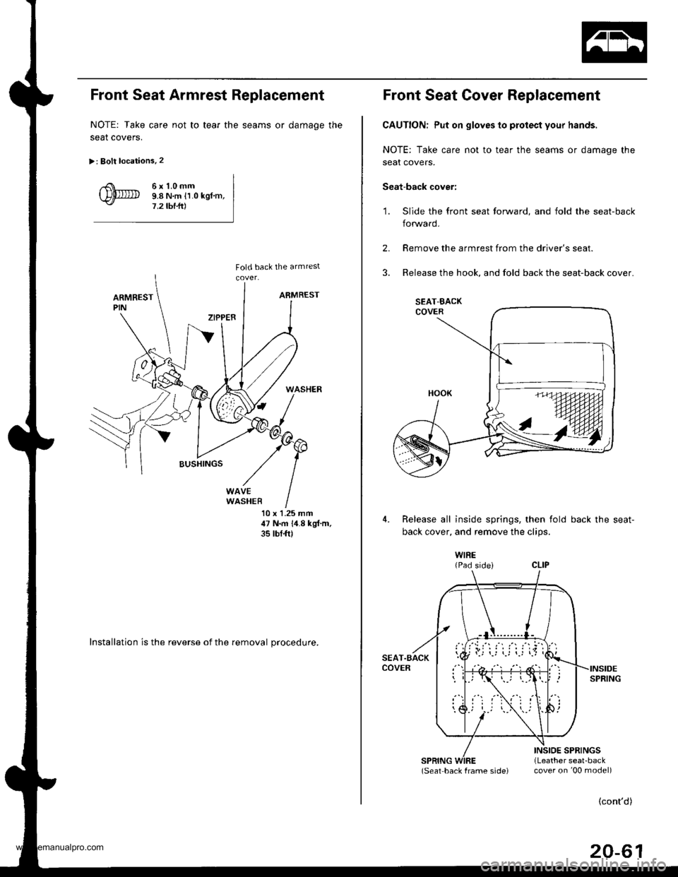
Front Seat Armrest Replacement
NOTE: Take care not to tear the seams or damage the
seat coverS.
>: Bolt locations.2
6r1.0mm9.8 N,m ll.0 kgl.m,7,2 tbf.ft)
10 x 1.25 mm47 N.m 1,1.8 kgf,m,35 tbt{t)
Installation is the reverse of the removal procedure.
Front Seat Cover Replacement
CAUTION: Put on gloves to protect your hands.
NOTE: Take care not to tear the seams or damage the
seat covers.
Seat-back cover:
'1. Slide the front seat forward, and fold the seat-back
forward.
2.
3.
Remove the armrest from the driver's seat.
Release the hook, and fold back the seat-back cover.
4.Release all inside springs, then fold back the seat-
back cover. and remove the clios.
WIRE{Pad sidei
(Seat back frame sjde) cover on '00 model)
(cont'd)
20-61
SEAT-BACK
www.emanualpro.com
Page 1044 of 1395
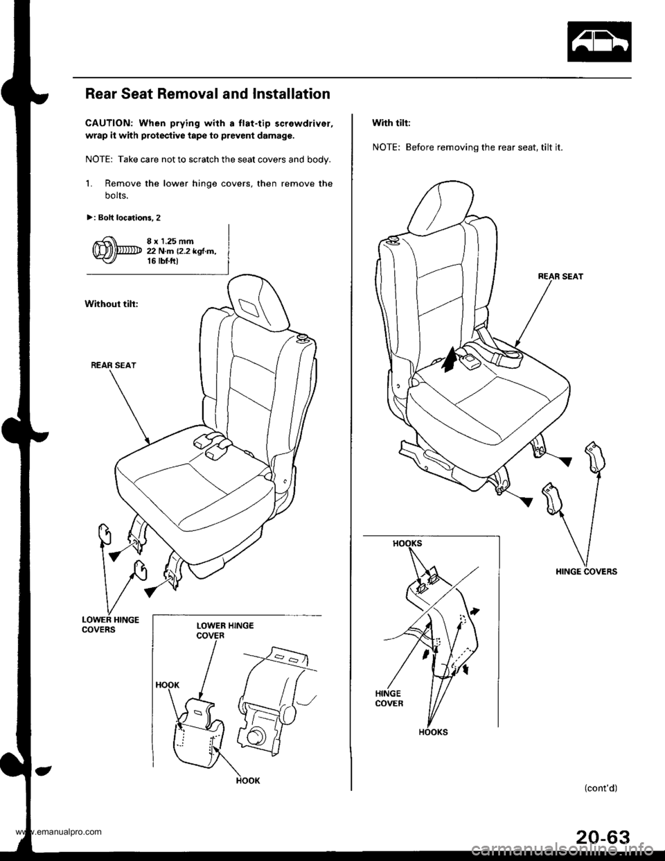
Rear Seat Removal and lnstallation
CAUTION: When prying with a llat-tip screwdrivsr,
wrap it with protective tape to prevent damage.
NOTE: Take care not to scratch the seat covers and bodv.
l� Remove the lower hinge covers, then remove the
bolts.
>: Boh locations. 2
8 r 1.25 mm2 N.m 12.2 kgl,n,16 tbf ttl
LOWER HINGEcovERsLOWER HINGECOVER
with tilt:
NOTE: Before removing the rear seat, tilt it.
(cont'd)
20-63
www.emanualpro.com
Page 1053 of 1395
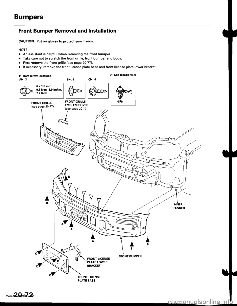
Bumpers
Front Bumper Removal and Installation
CAUTION: Put on gloves to protec,t your hands.
NOTE:
. An assistant is helpful when removing the front bumper.
. Take care not to scratch the front grille, lront bumper and body.
o First remove the front grille (see page 20-77).
. lf necessary, remove the front license plate base and front license plate lower bracket.
B>, 4 C>,4
4 .<\l
S))PF | ffi)m>lv I Y./ |
FRONT GRILLEEMBLEM COVER(see page 20-77)
>: Clip locations,5
.r., I
w€lw
FENDER
IB
FRONT BUMPER
20-72
>: Boli screw locationsA>,3
6x1.0mm9.8 N.m (1.0 kgf.m,7.2 tbt t0
FRONT GRILLE(see page 20-77)
tx -
\{_:
www.emanualpro.com