Connection HONDA CR-V 2000 RD1-RD3 / 1.G Service Manual
[x] Cancel search | Manufacturer: HONDA, Model Year: 2000, Model line: CR-V, Model: HONDA CR-V 2000 RD1-RD3 / 1.GPages: 1395, PDF Size: 35.62 MB
Page 1111 of 1395
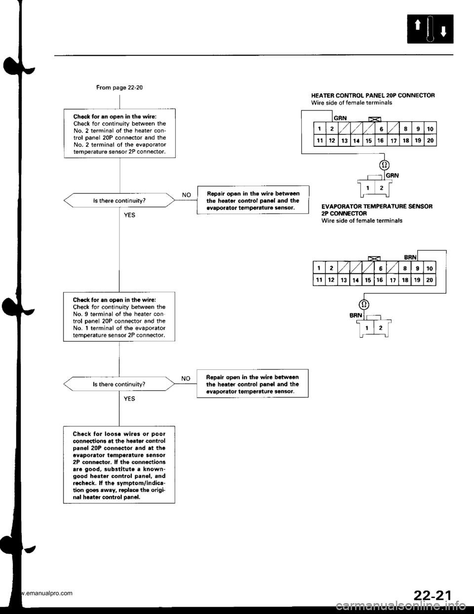
From page 22-20
Chock tor an oDen in th€ wire:Check for continuity betlveen theNo. 2 terminal of the heater con-trol oanel 20P connector and theNo.2 terminal oI the evaporatortemperature sensor 2P connoctor.
Fopair open in the wiro betweentho heato. control penel and theevaporator tempetatule sensor.
Check for rn opsn in tha wiJe:Check for continuity between theNo. 9 terminal of the heater control oanel 20P connector and theNo. 'l terminal ot the evaporatortemperature sensor 2P connector,
Ropair open in tho wire betwegnthe heater control oanel and theevaporator tgmpcrature sen3or.
Chgck fol loose wiros or pool
connectrons at the hoator controloan6l 20P connector and at theeveporator temperatura Sensol2P connector. It the connectionsare good, substitute a known-good he.tel contlol panel, andrech€ck. ll thg symptom/indica-tion 90o3 rwey, roplsce the origi-nal heater control oanel.
HEATER CONTROL PANEL 2OP CONNECTORWire side ol female terminals
EVAPORATOB TEMPERATURE SENSOR2P CONNECTORWire side oI temale terminals
1810
1112131a1516't7181920
GIIN
12,/ l,/689t0
'tl1213lat1516'1718't920
o
+
li-L:t
www.emanualpro.com
Page 1113 of 1395
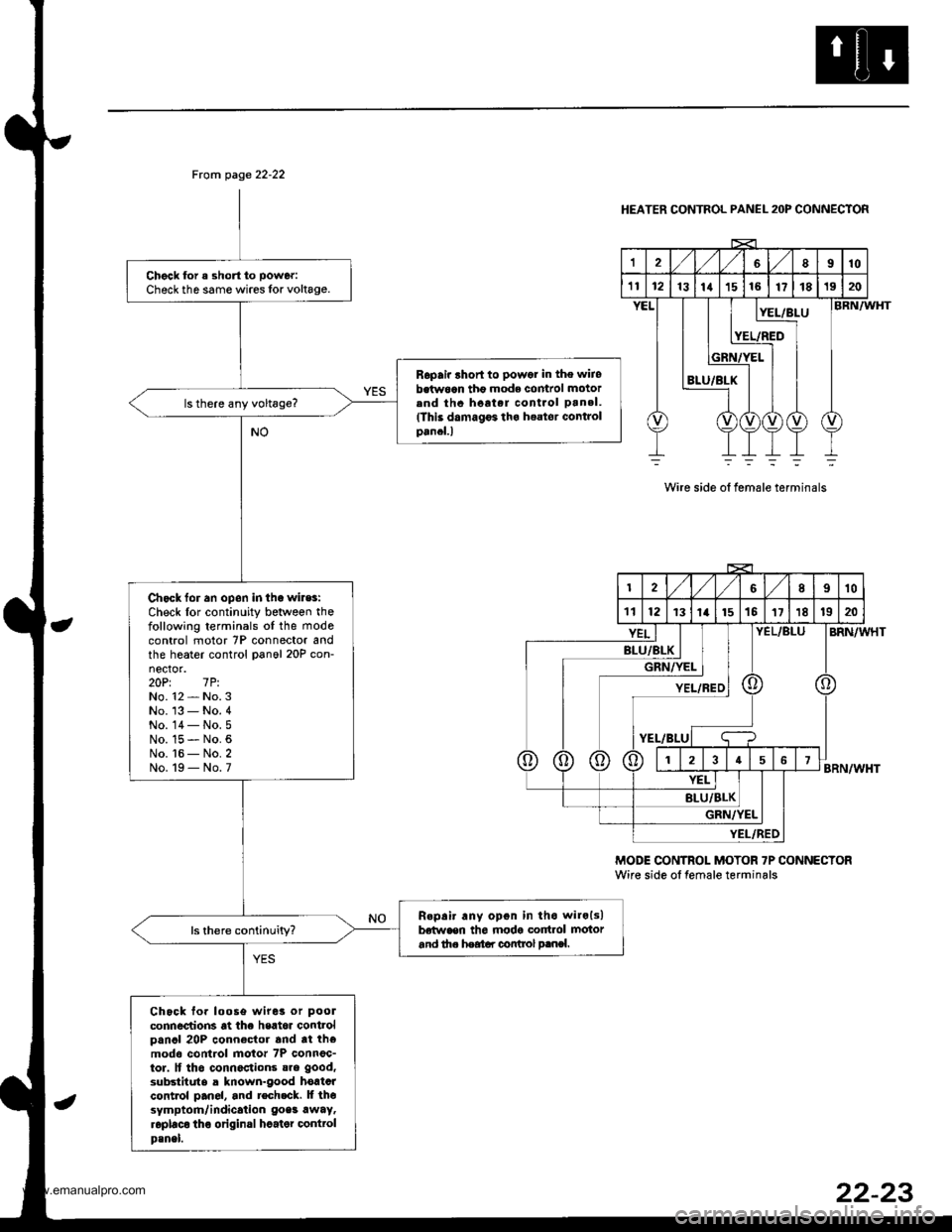
From page 22-22
Chgck for a short to power:
Check th6 same wires lor voltage.
Ropair lhort to powor in the wiiobetw6an tho mode comrol motorend thc hoat.r cont.ol pan.l.(This damagF tha h€ator Gontrolpancl.l
Chack for an opon in tha wiles:Check lor continuity between thefollowing terminals oI the mode
control motor 7P connector andthe heater control panol 20P con-nector.20Pt 7P.No. 12 - No. 3No. '13 - No. 4No. 14- No.5No. 15 - No. 6No. t6 - No. 2No. 19 - No. 7
R.pair any opon in tho wilols)betwaen th6 modg cortrol motorand th. heatar control p.nsl.
Chock fo. loose wiret or pool
connections at the heat6r controlpancl 20P connector and tt themodo control motor 7P connoc-tor. lf tho connactions sre good,
substitute a known-good hortcrcontrol pan6l, and tech.ck. lf thesymptom/indication goes awaytroplaco tho original hcater @nttolp3nel.
HEATER CONTROL PANEL 2OP CONNECTOR
12'VVLgl8910
't112rslrrlrslre17181920
8LU/BLX
:L/BLUBRN/WHT
BRN/WHT
BRN/WHT
Wire side ot female terminals
MODE CONTROI- MOTOR 7P CONNECTORWire side ol temale terminals
2,/1,/l/II10
111213t14t151511181920
BLU/BL
GRi
YEL/
Kt I I|/YEL I IIYEL/REDI
t-BLUI q
;f;T;T;
YEL/BLU
YEL
BLU/BLK
GRN/ItEL
YI:L/FED
22-23
www.emanualpro.com
Page 1115 of 1395
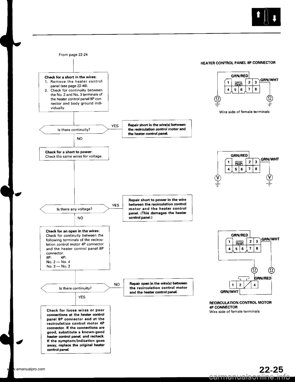
Ftom page 22-24
Check tol a short in the wit6:1. Remove the heater controlpanel {see page 22-46)2. Check for continuity betweenthe No.2 and No.3terminals of
the heater controlpanel8P connector and body ground indi-vidually.
Reoaii short in tfte wir€{s) b€irv€€nthe redrc{lstion conttol motor and
ihe hedter control panel.
Check for a shon to power:
Check the same wires lor voltage.
Repair short to power in the wite
between the rocirculation controlmotor and lh€ heator controlpanel. (This demsges the heater
conlrol panel.l
ls there any voltage?
Ch€ck tor an open in the wires:Check for continuity between thefollowing terminals ol the recircu'lation control motor 4P connectorand the heater control panel 8P
8P: 4P:No.2 - No.4No.3- No.2
Ropair open in the wile(sl betweenthe recirculalion control motorand the heeter cortrol Pan€|.
Check for loose wires or pool
connections at the heat€r control
Danel 8P connoctor and .t therocirculation control motor 4Pconnector. lf lhe connec{ions aregood, substitule a known-goodhester control oanel, and rochock.lI the symptom/indication goes
away, .eplace the otiginal heater
control pan€|.
HEATER CONTROL PANEL 8P CONNECTOR
Wire side of female terminals
GRN/REO---1 T'lF Iir l516 I
213
;T;
1ffiIVI4I
GRN/WHT
RECIRCULATION CONTROL MOTOR,lP CONNECTORwire side ot female terminals
22-25
www.emanualpro.com
Page 1123 of 1395
Both Fans
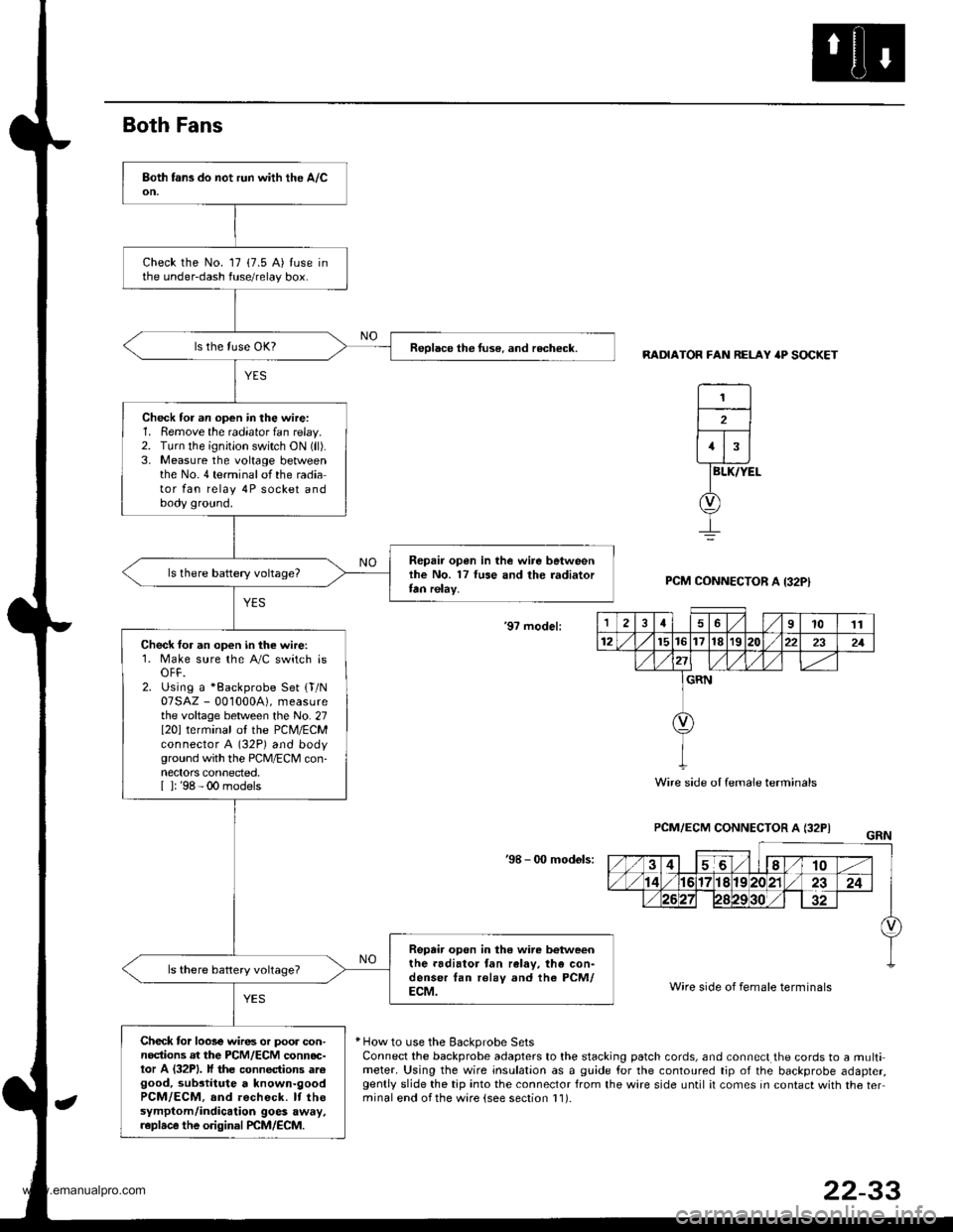
RADIATOR FAN RELAY 'P SOCKET
BLK/YEL
PCM CONNECTOR A I32PI
'9? model:
PCM/ECM CONNECTOR A (32PI
'98 - 0O mod6ls:
Wire side of female terminals
* How to use the Backprobe SetsConnect the backprobe adapters to the stacking patch cords, and connect the cords to a multimeter. Using the wire insulation as a guide for the contoured tip of the backprobe adapter,gently slide the tip into the connector from the wire side until it comes in contact with the terminal end ofthe ware {see section l1).
Check the No. 17 (7.5 A) tuse inthe under-dash fuse/relay box.
Reolace the tuse. and recheck.
Check for an op€n in the wire:1. Remove the radiator fan relay.2. TLrrn the ignition switch ON (ll).
3. Measure the voltage betweenthe No.4 terminalofthe radiator fan relay 4P socket andbody ground.
Repair open in the wire betweenlhe No. 17 luse and the radiatortan relay.
Check for an open in the wire:1. Make sure the A/C switch isOFF.2. Using a *Backprobe Set {T/N07SAZ - 001000A), measurethe voltage between the No. 27I20l terminal ol the PCM/ECMconnector A (32P) and bodyground with the PCM/ECM con-nectors connected.[ ]: '98 - 00 models
Repair open in the wire b€tweenthe.adiator fan ralav, the con-denser tan rolay and the PCM/ECM.
Check tor loose wires or poor con-nodions at the PCM/ECM connoc-tor A (32P1. lf the connections arcgood, substitute a known-goodPCM/ECM, and recheck. It thesymptom/indicalion goes away,r.plrce the original PCM/ECM.
1
2
1
12461011
12t5t61718r9222321
GRN
Wire side oI female terminals
22-33
www.emanualpro.com
Page 1126 of 1395
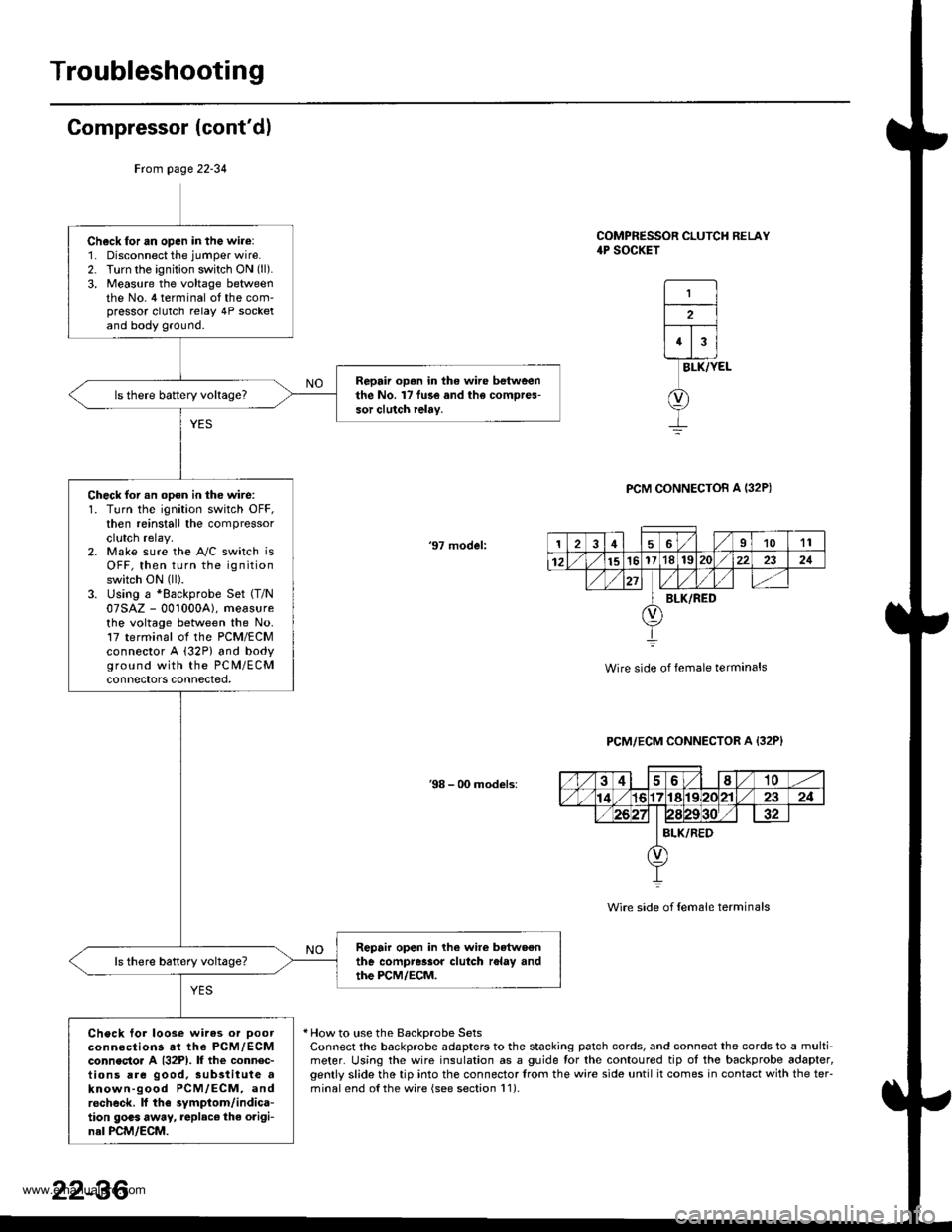
Troubleshooting
Compressor (cont'dl
COMPRESSOR CLUTCH RELAY4P SOCKET
1
2
43
BLK/YEL
PCM CONNECTOB A I32P)
'97 model:
Wire side of female terminals
PCM/ECM CONNECTOR A {32P}
38 - 00 models:
Wire side of {em6le terminals
* How to use the BackDrobe SetsConnect the backprobe adapters to the stacking patch cords, and connect the cords to a multi-meter. Using the wire insulation as a guide for the contoured tip ot the backprobe adapter,gently slide the tip into the connector trom the wire side until it comes in contact with the teFminalend o{the wire {see section l1).
Frcm page 22-34
Ch6ck for an open in the wire:1. Disconnect the jumper wire.2. Turn the ignition switch ON (ll).
3, Measure the voltage betweenthe No. 4 terminal ot the com'pressor clutch relay 4P socketand body ground.
Repair op.n in the wire betweenthe No. l7 fu3e and the compres-sor clutch ielay.
Check for an opon in the wire:1. Turn the ignition switch OFF,then reinstall the compressorclutch relay.2. Make sure the A"/C switch isOFF, then turn the ignitionswitch ON (ll).
3. Using a *Backprobe Set (T/N
07SAZ - 001000A), measurethe voltage between the No.17 terminal ol the PCM/ECMconnector A (32P) and bodyground with the PC M/ECMconnectors connected,
Repair open in lhe wire betwoonthe compressor clutch r6lay andthe PCM/ECM.
Check tor loose wires or Doorconnections at the PCM,/ECMconnecto. A {32P1. lf the connec-tions are good, sub3titute aknown-good PCM/ECM, androcheck. lf the symptom/indica-tion goas away, replac€ the origi-nal PCM/ECM.
126I1011
12151617'181S222321
BLK/RED
22-36
www.emanualpro.com
Page 1127 of 1395
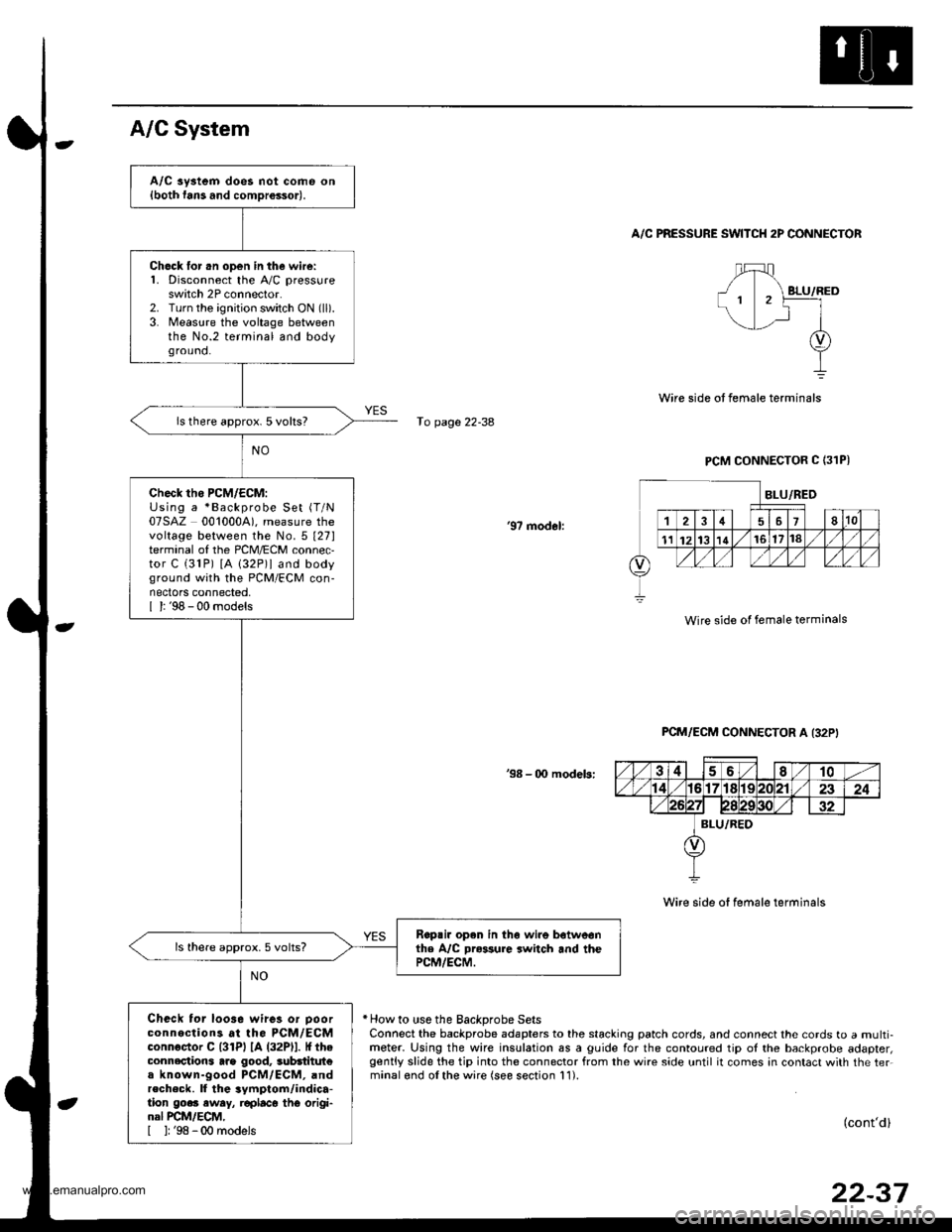
A/C aystem does not come on{both fans and comDrossor).
Ch6ck lor .n open in the wire:1. Disconnect the A,/C pressureswitch 2P connector.2. Turn the ignition switch ON (ll).
3. Measure the voltage betweenthe No.2 terminal and bodyground.
ls there approx. 5 volts?
check tho PcM/EcM:Using a *Backprobe Set (T/N
07SAZ 0010004). measure thevoltage between the No.5 t27lterminal of the PCM/ECM connec,tor C (31P) [A 132P)l and bodyground with the PCM/ECM con-nectors connected,I l: '98 - 00 models
Rop.ir open in th6 wire botweonthe A/C Dr*sure switch and thePCM/ECM.
ls there approx.5 volts?
Check tor loo3e wires or Doorconnections at the PCM/ECMconnoctor C l3lPl lA (32Pll. It theconnections arg good, 3ubdtitut€a known-good PCM/ECM, andrecheck. ll the 3ymptom/indica-tion go.. eway, r€placo thG origi-nal PCM/ECM,[ ]: '98 -00 models
A/C System
A/C PRESSURE SWITCH 2P CONNECTOR
fo page 22-38
PCM CONNECTOR C (31PI
'97 modol:
Wire side of female terminals
PCM/ECM CONNECTOR A I32P'
38 - 00 modeb:
Wire side of female terminals
* How to use the Backprobe SetsConnect the backprobe adapters to the stacking patch cords, and connect the cords to a multi-meter. Using the wire insulation as a guide for the contoured tip ol the backprobe adapter,gently slide the tip into the connector from the wire side until it comes in contact with the ter.minalond olthe wire (see section 11).
(cont'd)
22-37
www.emanualpro.com
Page 1128 of 1395
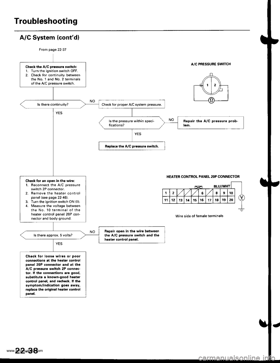
Troubleshooting
A/G System {cont'd)
From page 22-37
A/C PRESSURE SWITCHCheck th€ A/C pressure switch:1. Turn the ignition switch OFF.2. Check lor continuity bgtweenthe No. 1 and No.2 terminalsofthe A,/C pressure switch.
Check for proper Ay'C system pressure.
Roplece tha A/C pr€ssure switch.
Chock lor an opgn in thg wire:1. Feconnect the A/C pressure
switch 2P connector,2. Remove the heater controlpanel (see page 22-46).3. Turn the ignition switch ON llli.4. Measure the voltage betweenthe No. 10 terminal of theheater control panel 20P con-nector and body ground.
Repair open in the wir. botwcenthe A/C pres3ur€ switch and theheater control oanel.ls there approx. 5 volts?
Check lor loos6 wiras or pool
connections at the heater controlDanel 20P connoctor and at theA/C pr.ssule switch 2P connsc-tor. lf the connections ere good,
substitute a known-good heatarco trol pangl, end recheck. lf thesymptom/indication goes away,replace the original heater conlrolpanel.
HEATER CONTROL PANEL 2OP CONNECTOR
Wire side ol female terminals
22-38'
www.emanualpro.com
Page 1129 of 1395
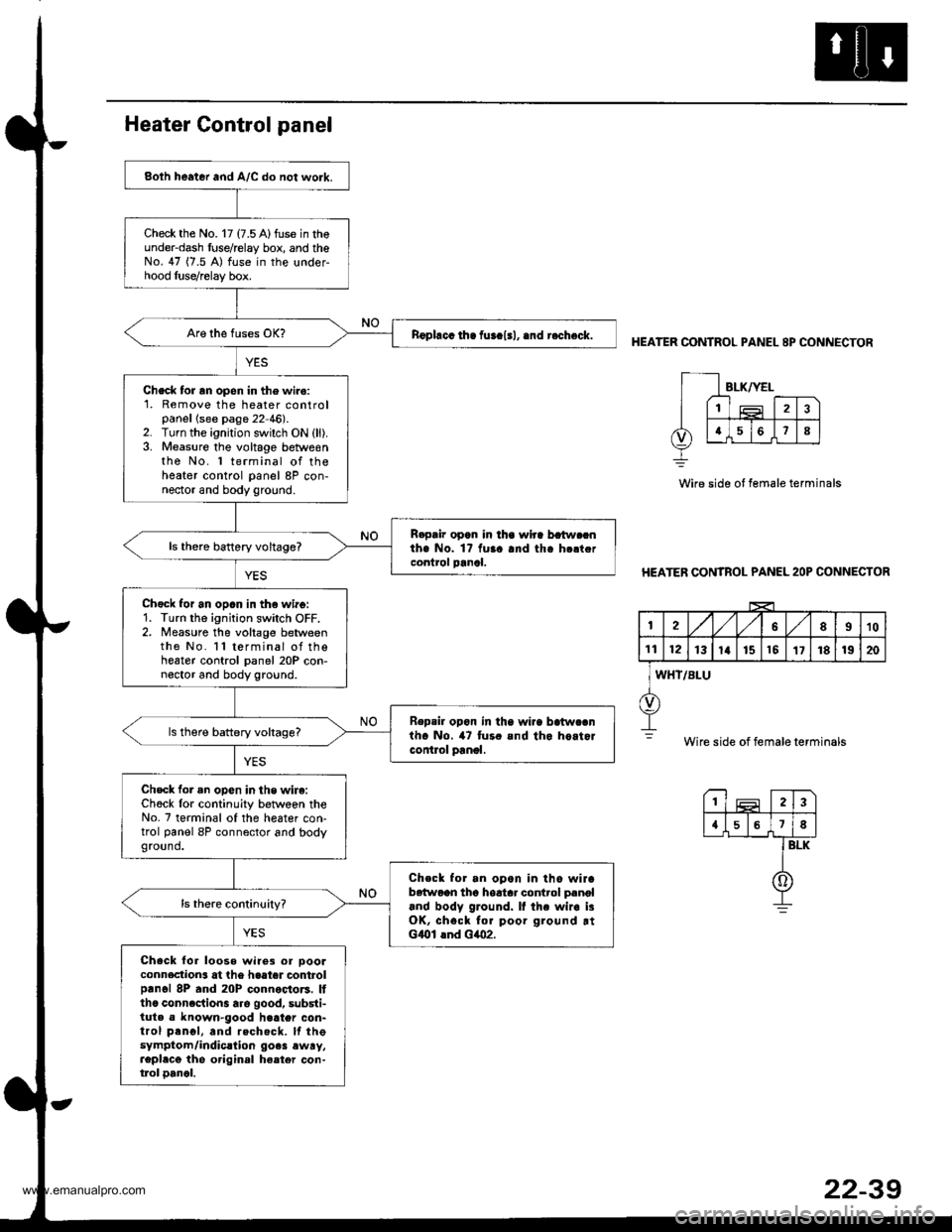
Both heater and A/C do not work.
Check the No. 17 (7.5 A)fuse in theunder-dash fuse/relay box, and theNo. 47 (7.5 A) fuse in the under-hood luse/relay box.
nophcc ih. fur.l.l, .nd r.check.
Check tor rn open in the wiro:1. Remove the heater controlpanellsee page 22 46).2. Turn the ignition switch ON (ll).3. Measure the voltage betweenthe No. 1 terminal of theheater control panel 8P con-nector and body ground.
R.pair opan in lha wlra batw.cnthe No. 1? fuaa and tha h.ltcrcontrol panal.ls thero battery voltage?
Chgck for an opan in th€ wirg:1. Turn the ignition switch OFF.2. Measure the voltage betweenthe No. l l terminal of thoheater control panel 20P con-noctor and body ground.
Repsil opon in tha wi.a batwcanth. No. 47 tur. and tho hoitorcontlol panol.
ls there battery voltags?
Check for an opon in the wire:Ch6ck lor continuity betwoen theNo. 7 terminal of the heater con-trol panel 8P connector and bodyground.
Check for an opon in tho wirab6{woon tho hoatar control p.noland body ground. It the wir. i3OK, chsck for poor ground rtGlOl lnd Glo2.
Check for loose wire3 or oooaconnection3 at the haater controlprnol 8P and 20P connoctors. Itthc conncction3 are good, substi-tuta a known-good h€ater con-trol prnol, and rechecft. lf thesymptom/indic.lion go.3 ewry,repl.cg the original ha.ter con-tlol oancl.
HEATER CONTROL PANEL 8P CONNECTOR
Wire side ot female terminals
HEATER CONTROL PANEL 2OP CONNECTOR
I2A,/1,/58910
1t12131a151517181920
WHT/BLU
Wire side of female terminals
23
{578
BLK
0
www.emanualpro.com
Page 1131 of 1395
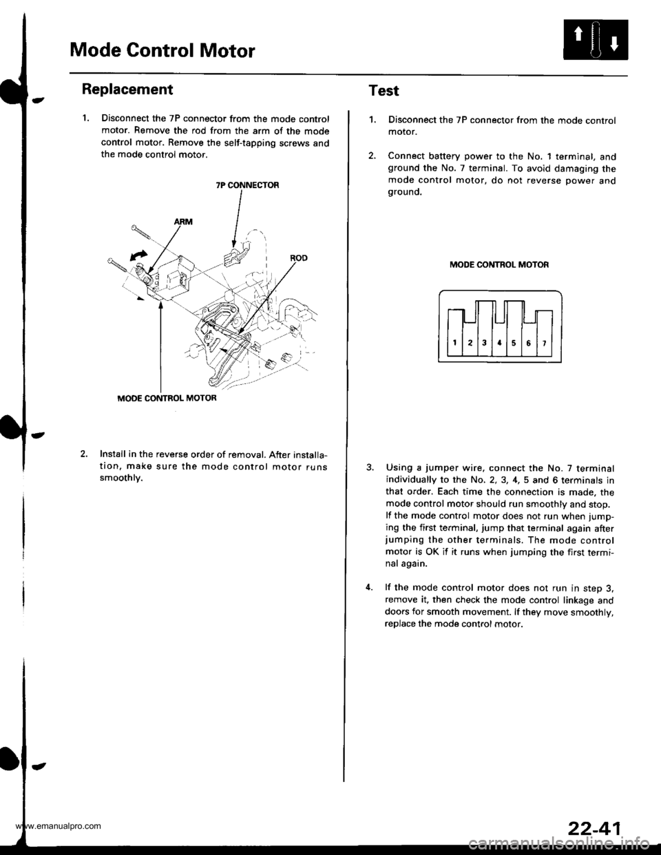
Mode Control Motor
Replacement
1. Disconnect the 7P connector from the mode control
motor. Remove the rod from the arm of the mode
control motor, Remove the self-tapping screws and
the mode control motor.
2.Install in the reveGe order of removal. After installa-
tion, make sure the mode control motor runssmoothlv.
7P CONNECTOR
MODE CONTROL MOTOR
Test
1.Disconnect the 7P connector from the mode control
motor.
Connect battery power to the No. 1 terminal, andground the No. 7 terminal. To avoid damaging the
mode control motor, do not reverse power andgrouno.
MODE CONTROL MOTOR
Using a jumper wire. connect the No. 7 terminalindividually to the No, 2,3, 4,5 and 6 terminals in
that order. Each time the connection is made. the
mode control motor should run smoothly and stop.
lf the mode control motor does not run when jump-
ing the first terminal, jump that terminal again afterjumping the other terminals. The mode control
motor is OK it it runs when jumping the first termi-
nal again.
lf the mode control motor does not run in step 3,remove it, then check the mode control linkage and
doors for smooth movement. lf they move smoothly,
reDlace the mode control motor.
www.emanualpro.com
Page 1133 of 1395
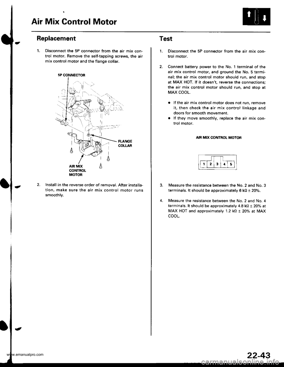
Air Mix Gontrol Motor
Replacement
1. Disconnect the 5P connector from the air mix con-
trol motor. Remove the self-tapping screws, the air
mix control motor and the flange collar.
AIR MIXCONTROLMOTOR
A
6
Install in the reverse order of removal. After installa-
tion. make sure the air mix control motor runs
smoothlv.
5P CONNECTOR
22-43
Test
1.Disconnect the 5P connector from the air mix con-
trol motor.
Connect battery power to the No. I terminal of the
air mix control moto., and ground the No, 5 termi-
nal; the air mix control moto. should run, and stop
at MAX HOT. lf it doesn't, reverse the connections;
the air mix control motor should run, and stoo at
MAX COOL.
lf the air mix control motor does not run, remove
it, then check the air mix control linkage and
doors for smooth movement.
lf they move smoothly, replace the air mix con-
trol motor.
AIR MIX CONTROL MOTOR
4.
Measure the resistance between the No. 2 and No. 3
terminals. lt should be approximately 6 kO t 20%.
Measure the resistance between the No. 2 and No, 4
terminals, lt should be approximately 4.8 kO:t 20% at
MAX HOT and approximately '1.2 kO t 20% at lilAx
cooL.
www.emanualpro.com