Solenoid HONDA CR-V 2000 RD1-RD3 / 1.G Repair Manual
[x] Cancel search | Manufacturer: HONDA, Model Year: 2000, Model line: CR-V, Model: HONDA CR-V 2000 RD1-RD3 / 1.GPages: 1395, PDF Size: 35.62 MB
Page 532 of 1395
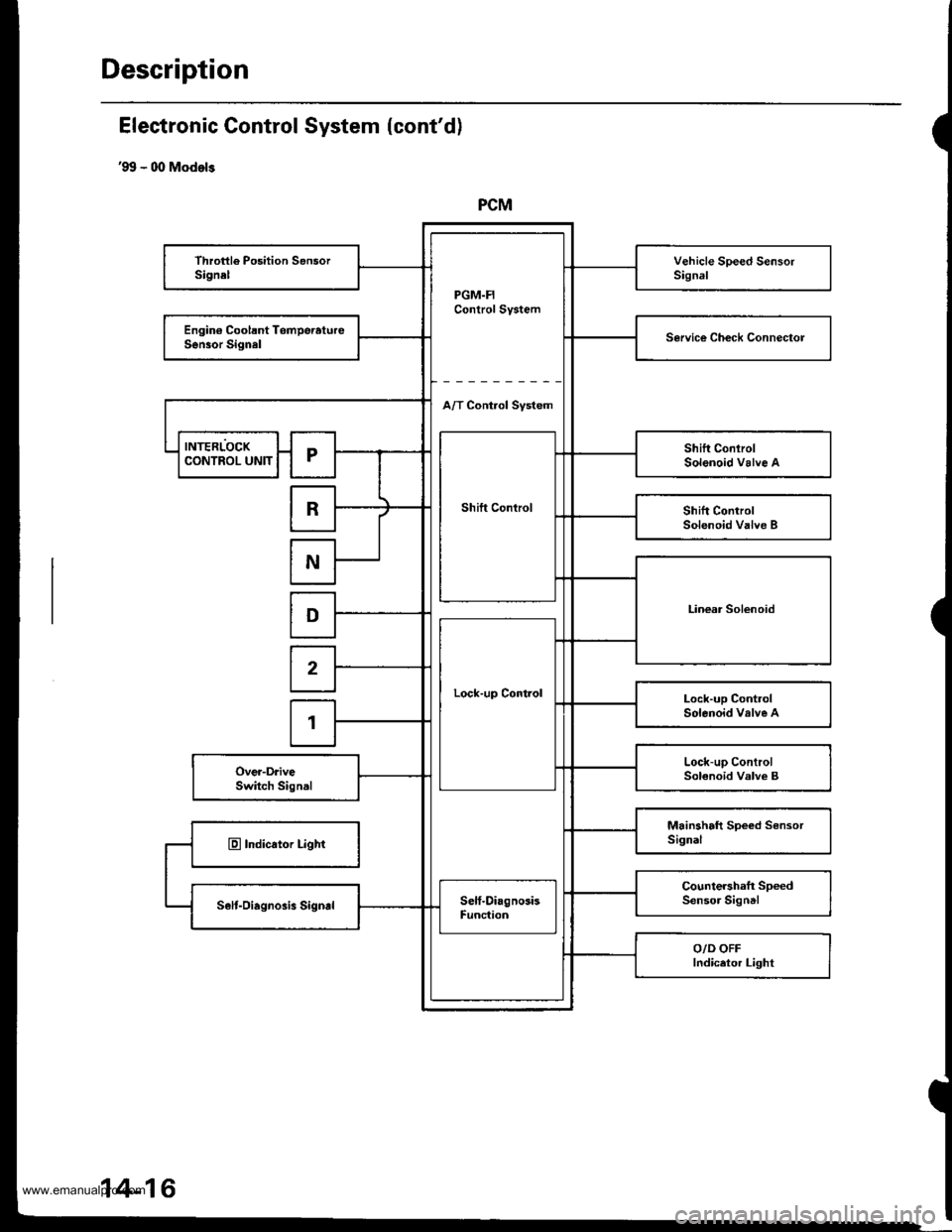
Description
PCM
PGM.FIControl System
Throttle Position SensorSignelVehicle Speed SensorSignal
Engin€ Coolsnt TomperatureSen30r SignalService Ch€ck Connectol
A/T Control Svstem
INTERLOCK
Shift Control
Shift ConlrolSolenoid Valve ACONTROL UNITr
RShift ControlSolenoid Valve B
N
Linear SolenoidD
Lock-up Control
2
Lock-up ControlSolenoid valve A1
Lock-up ControlSolenoid Valve BOver-DriveSwitch Signal
Mainshaft Speed SensorSignalE Indicator Light
Countershaft SpeedSensor SigntlSelt-Oiagnosis SigndSelf-DiagnosisFunc{ion
O/D OFFIndicetor Light
Electronic Gontrol System (cont'd)
'99 - 00 Models
14-16
www.emanualpro.com
Page 533 of 1395
Shift Control
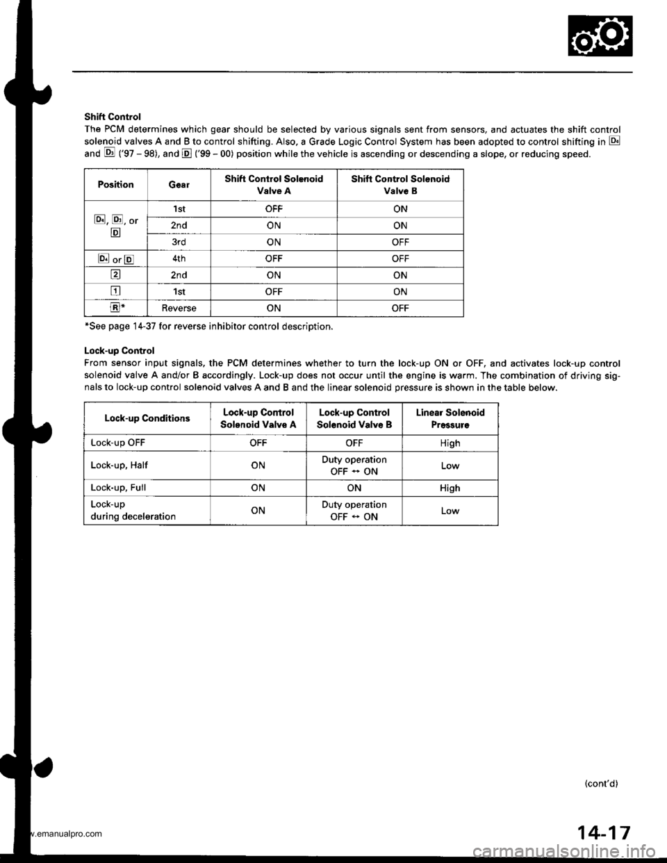
The PCM determines which gear should be selected by various signals sent from sensors, and actuates the shift control
solenoid valves A and B to control shifting. Also. a Grade Logic Control System has been adopted to control shifting in E
anO E ('gZ - gg), and E ('99 - 00) position while the vehicle is ascending or descending a slope, or reducing speeo.
PositionGearShift Control Solenoid
Valve A
Shift Control Solonoid
Valve B
E, E, Or
E
'I stOFFON
2ndONON
3rdONOFF
E orE4thOFFOFF
a2ndONON
tr1stOFFON
E-ReverseONOFF
*See page 14-37 for reverse inhibitor control description.
Lock-up Control
From sensor input signals, the PCM determines whether to turn the lock-up ON or OFF, and activates lock-up control
solenoid valve A and/or B accordingly. Lock-up does not occur until the engine is warm. The combination of driving sig-
nals to lock-up control solenoid valves A and B and the linear solenoid pressure is shown in the table below.
Lock-up ConditionsLock-up Control
Solonoid Valve A
Lock-up Control
Solenoid Valve B
Linear Solenoid
Pressuro
LOCK-Up \JrrOFFOFFHigh
Lock-up, HalfONDuty operation
OFF - ON
Lock-up, FullONONHish
Lock-up
during decelerationONDuty operation
OFF - ONLow
(cont'd)
14-17
www.emanualpro.com
Page 537 of 1395
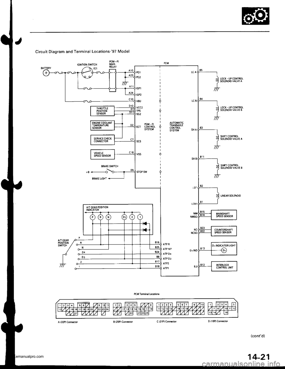
Circuit Diagram and Terminal Locationsr9T Model
IGNITIONSWITCH
LOC( UPCONTROL
LOCK UPCONTROLSOLEITOIDVALVE B
sf Frc0|lltF0LSOLENOIDVALVE A
sHrFr c0r{TnoLSOLEI{OID VALVE B
UNEASSOLINOID
14-21
www.emanualpro.com
Page 540 of 1395
Description
Hydraulic Control
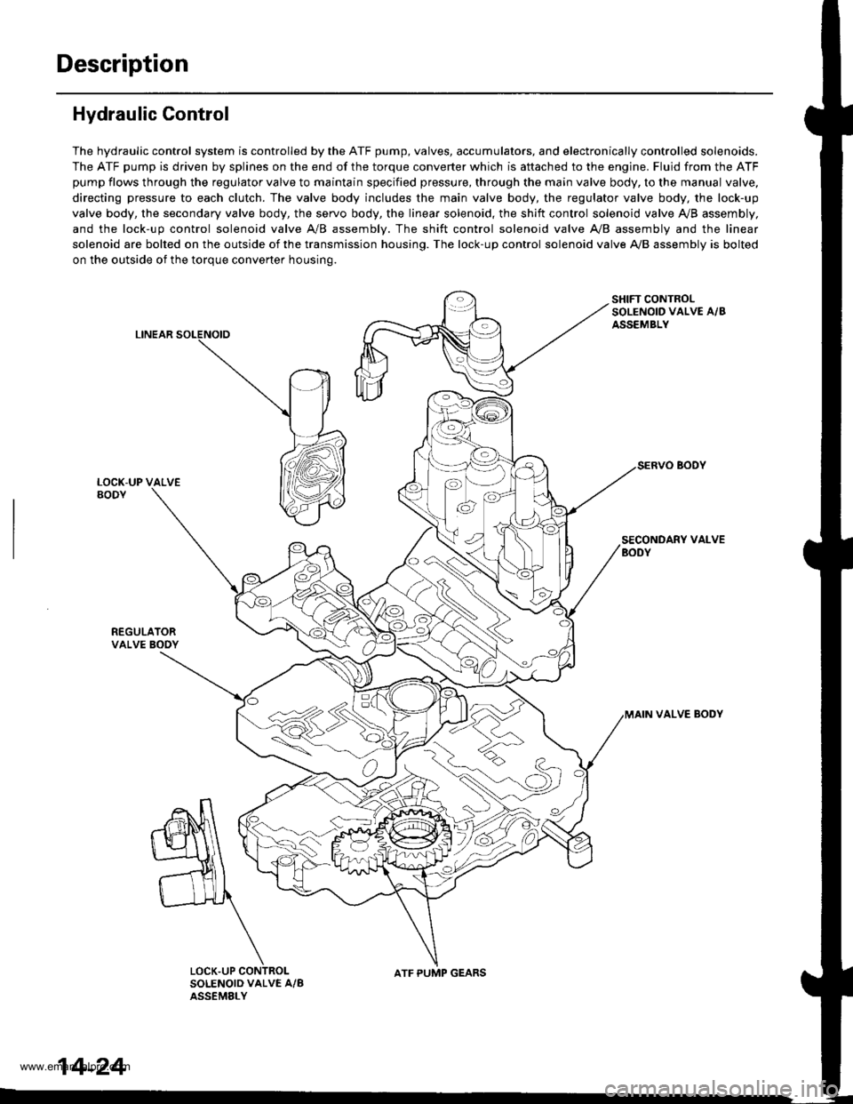
The hydraulic control system is controlled by the ATF pump, valves, accumulators, and electronically controlled solenoids.
The ATF pump is driven by splines on the end of the torque converter which is aftached to the engine. Fluid from the ATF
pump flows through the regulator valve to maintain specified pressure, through the main valve body, to the manual valve,
directing pressure to each clutch. The valve body includes the main valve body, the regulator valve body, the lock-up
valve body, the secondary valve body, the servo body, the linear solenoid, the shift control solenoid valve Ay'B assembly,
and the lock-up control solenoid valve A/B assembly. The shift control solenoid valve A,/B assembly and the linear
solenoid are bolted on the outside of the transmission housing. The lock-up control solenoid valve A,/B assembly is bolted
on the outside of the torque converter housing.
LINEAR
SHIFT CONTROLSOLENOID VALVE A/BASSEMBLY
SECONDARY VALVEBODY
REGULATORVALVE BOOY
VALVE BODY
SOLENOID VALVE A/BASSEMELY
N
ATF PUMP GEARS
14-24
www.emanualpro.com
Page 545 of 1395
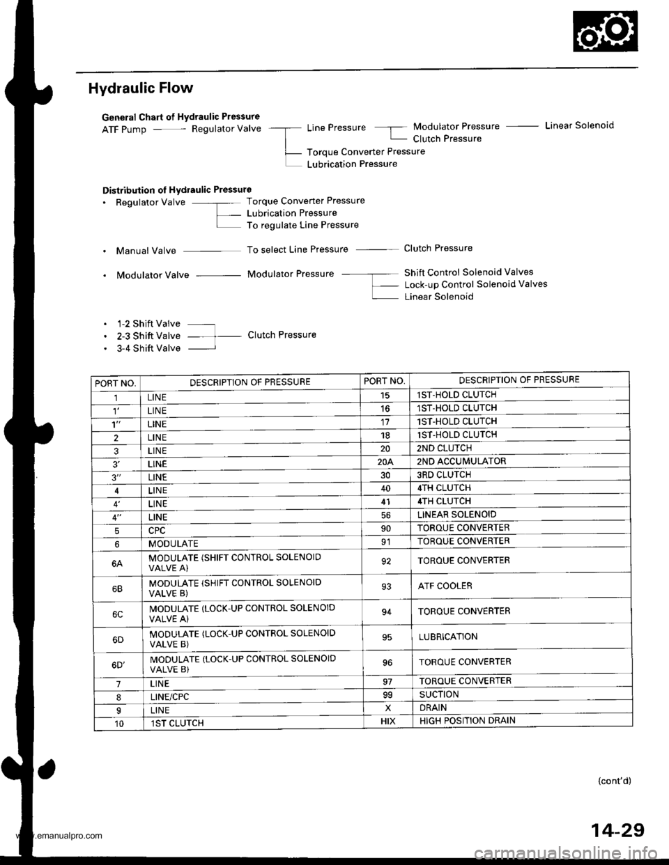
Hydraulic Flow
General Chart of Hydraulic Pressure
ATF pump - Regulator Valve -a LinePressure 5 Modulator Pressure - Linear Solenoid
| - Clutch Pressure
L- Toroue Converter Pressure
L LUbrication Pressure
Distribution ol Hydraulic Pressure
. Regulator Valve -"- Torque Converter Pressure
L- Lubrication PressureI To regulate Line Pressure
. Manual Valve To select Line Pressure - Clutch Pressure
. Modulator Valve Modulator Pressure -- ---- Shift Control Solenoid Valves
f- Lock-up Control Solenoid valves
L Linear Solenoid
. 1-2 Shift Valve ---
. 2-3 Shift Valve -- t- Clutch Pressure
. 3-4 Shift Valve I
PORT NO,DESCRIPTION OF PRESSUREPORT NO,DESCRIPTION OF PRESSURE
1LINE15lST-HOLD CLUTCH
LIN E1ST-HOLD CLUTCH
't'LINE171ST-HOLD CLUTCH
2LINE181ST-HOLD CLUTCH
3LINE202ND CLUTCH
3'�LINE20A2ND ACCUMULATOR
3"LINE303RD CLUTCH
LINE404TH CLUTCH
LINE414TH CLUTCH
LINELINEAR SOLENOID
590TOROUE CONVERTER
MODULATE91TOROUE CONVERTER
6AMODULATE (SHIFT CONTROL SOLENOIOVALVE A)92TOROUE CONVERTER
MODULATE (SHIFT CONTROL SOLENOID
VALVE B)93ATF COOLER
IVODULATE (LOCK.UP CONTROL SOLENOID
VALVE A)94TOROUE CONVERTER
MODUTATE (LOCK-UP CONTROL SOLENOID
VALVE B)95LUBRICATION
6D'MODULATE (LOCK-UP CONTROL SOLENOID
VALVE B)TOROUE CONVERTER
7LIN E97TOROUE CONVERTER
8LINE/CPC99SUCTION
ILINExDRAIN
101ST CLUTCHHIXHIGH POSITION DRAIN
{cont'd)
14-29
www.emanualpro.com
Page 547 of 1395
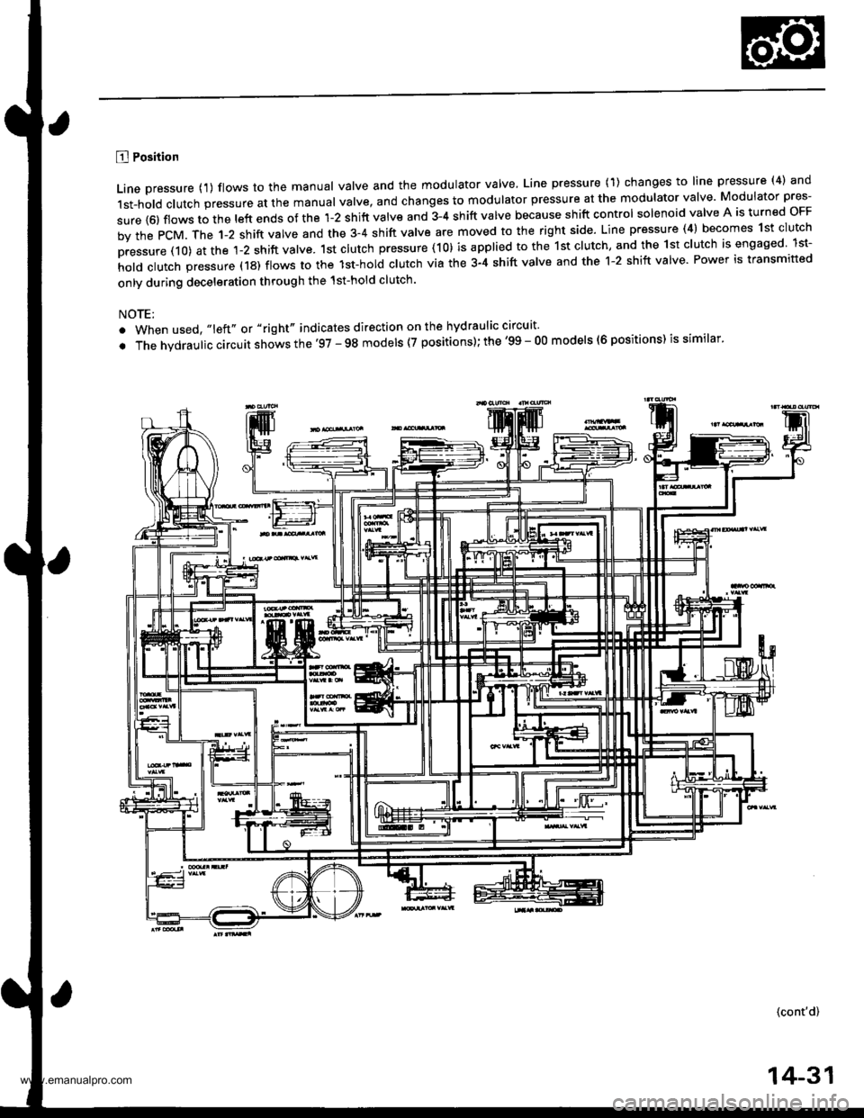
B Position
Line pressure {1) flows to the manual valve and the modulator valve, Line pressure (1) changes to line pressure (4) and
1st-hold clutch pressure at the manual valve, and changes to modulator pressure at the modulator valve Modulator pres-
sure {6) flows to the left ends of the 1-2 shift valve and 3-4 shift valve because shift control solenoid valve A is turned oFF
by the PcM. The 1-2 shift valve and the 3-4 shift valve are moved to the right side. Line pressure (4) becomes 1st clutch
pressure (10) at the 1-2 shift valve. 1st clutch pressure (10) is applied to the 1st clutch, and the 1st clutch is engaged lst-
hold clutch pressure (18) flows to the lst-hol; clutch via the 3-4 shift valve and the 1-2 shift valve Power is transmitted
only during deceleration through the 1st-hold clutch.
NOTE:
. When used, "left" or "right" indicates direction on the hydraulic circuit'
. The hvdraulic circuit shows the'97 - 98 models (7 positions); the '99 - O0 models (6 positions) is similar'
(cont'd)
14-31
www.emanualpro.com
Page 548 of 1395
Description
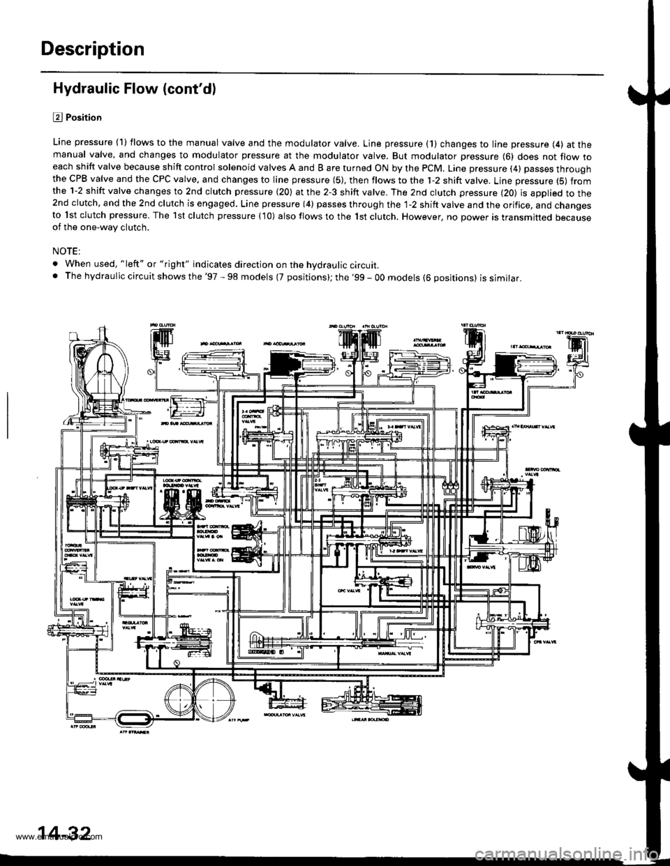
Hydraulic Flow (cont'dl
l?J Position
Line pressure {1) flows to the manual valve and the modulator valve. Line pressure (1} changes to line pressure (4) at themanual valve, and changes to modulator pressure at the modulator valve. But modulator pressure {6} does not flow toeach shift valve because shift control solenoid valves A and B are turned ON by the PCM. Line pressure (4) passes throughthe CPB valve and the CPC valve, and changes to line pressure (5), then flows to the 'l-2 shift valve. Line pressure (5) fromthe 1-2 shift valve changes to 2nd clutch pressure (20) at the 2-3 shift valve. The 2nd clutch pressure (20) is applied to the2nd clutch, and the 2nd clutch is engaged, Line pressure (4) passes through the 1-2 shift valve and the orifice, and changesto lst clutch pressure. The 1st clutch pressure {10) also flows to the 1st clutch. However, no power is transmitted becauseof the one-way clutch.
NOTE:
. When used, "left" or "right" indicates direction on the hvdraulic circuit.. The hydraulic circuit shows the '97 - 98 models (7 positions); the '99 - OO models (6 positions) issimilar.
14-32
www.emanualpro.com
Page 549 of 1395
![HONDA CR-V 2000 RD1-RD3 / 1.G Repair Manual
E] or E Position (97 - 98 Models), and D Position (99 - 00 Modelsl
1. lst Gear
Fluid flow through the torque converter circuit is the same as in E] position. Line pressure flows to the manual valve HONDA CR-V 2000 RD1-RD3 / 1.G Repair Manual
E] or E Position (97 - 98 Models), and D Position (99 - 00 Modelsl
1. lst Gear
Fluid flow through the torque converter circuit is the same as in E] position. Line pressure flows to the manual valve](/img/13/5778/w960_5778-548.png)
E] or E Position ('97 - 98 Models), and D Position ('99 - 00 Modelsl
1. lst Gear
Fluid flow through the torque converter circuit is the same as in E] position. Line pressure flows to the manual valve
and the modulator valve. Line pressure changes to modulator pressure (6) at the modulator valve and to line pressure
{4) at the manual valve. Modulator pressure (6) flows to the left end of the 1-2 shift valve and the 3-4 shift valve
because shift control solenoid valve A is turned oFF and B is turned oN by the PcM. The 1-2 shift valve is moved to
the right side. Line pressure {4) changes to 'lst clutch pressure (10} at the 1-2 shift valve and the orifice The 1st clutch
pressure (10) is applied to the 1st clutch and the 1st accumulator; the vehicle will move as the engine power is trans-
mitted.
NOTE:
. When used, "left" or "right" indicates direction on the hydraulic circuit.
. The hvd rau lic circuit shows th e '97 - 98 models (7 positions); the '99 - 00 models {6 positions) issimilar.
(cont'dl
14-33
www.emanualpro.com
Page 550 of 1395
Description
Hydraulic Flow (cont'dl
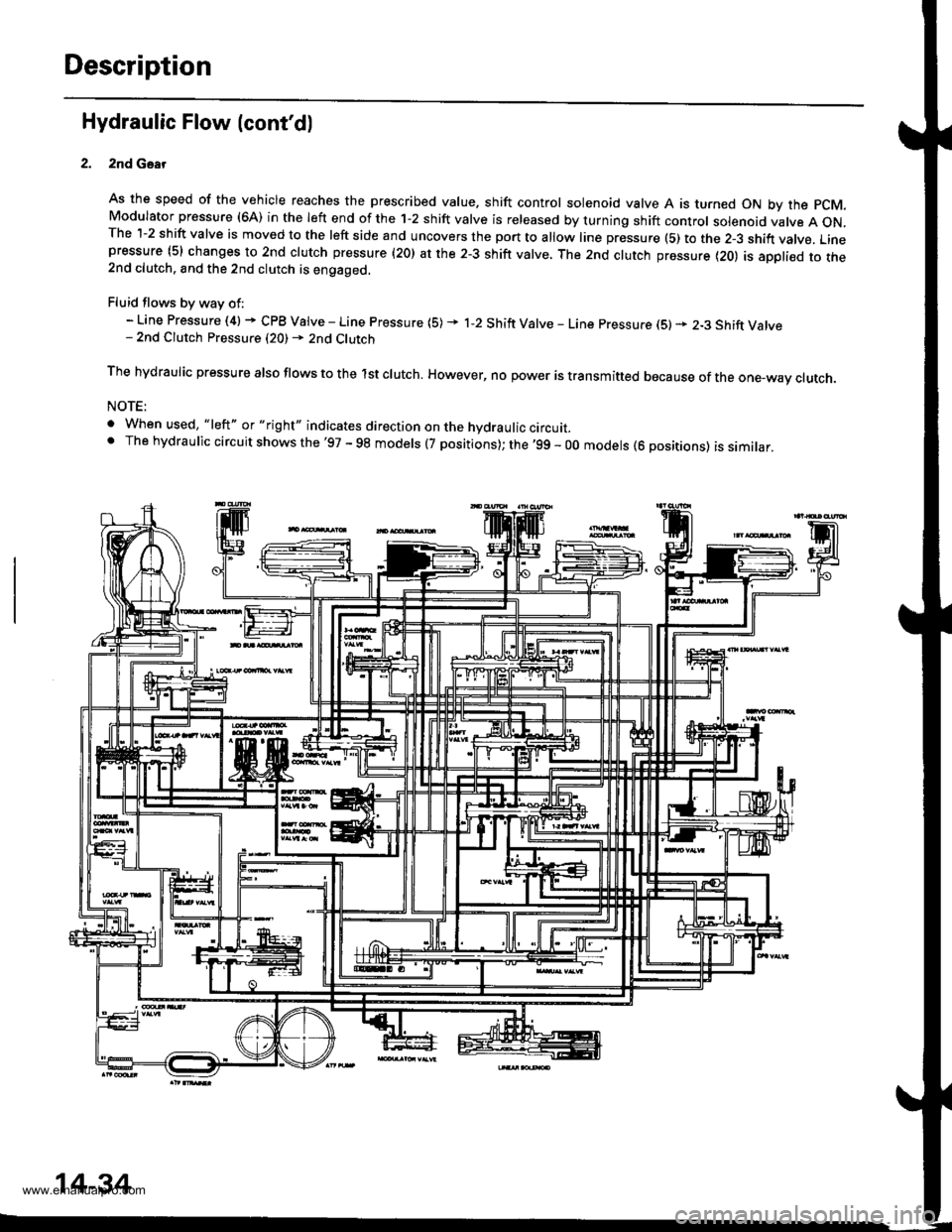
2nd Gsar
As the speed of the vehicle reaches the prescribed value. shift control solenoid valve A is turned ON by the pCM.Modulator pressure (6A) in the left end of the 1-2 shift valve is released by turning shift control solenoid valve A ON.The 1-2 shift valve is moved to the left side and uncovers the port to allow line pressure (5) to the 2-3 shift vatve. Linepressure (5) changes to 2nd clutch pressure (20) at the 2-3 shift valve, The 2nd clutch pressure {20) is appli€d to the2nd clutch. and the 2nd clutch is engaged.
Fluid flows by way of:- Line Pressure (4) + CPB Valve - Line Pressure (5) * 1-2 Shift Valve - Line pressure (S) * 2-3 Shift Valve- 2nd Clutch Pressure (20) - 2nd Clutch
The hydraulic pressure also flows to the lst clutch. However, no power is transmitted because of the one-wav ctutch.
NOTE:
. When used, "|eft" or "right" indicates direction on the hydraulic circurr_' The hydraulic circuit shows the'97 - 98 models (7 positions); the '99 - 00 models (6 positions) is similar,
14-34
www.emanualpro.com
Page 551 of 1395
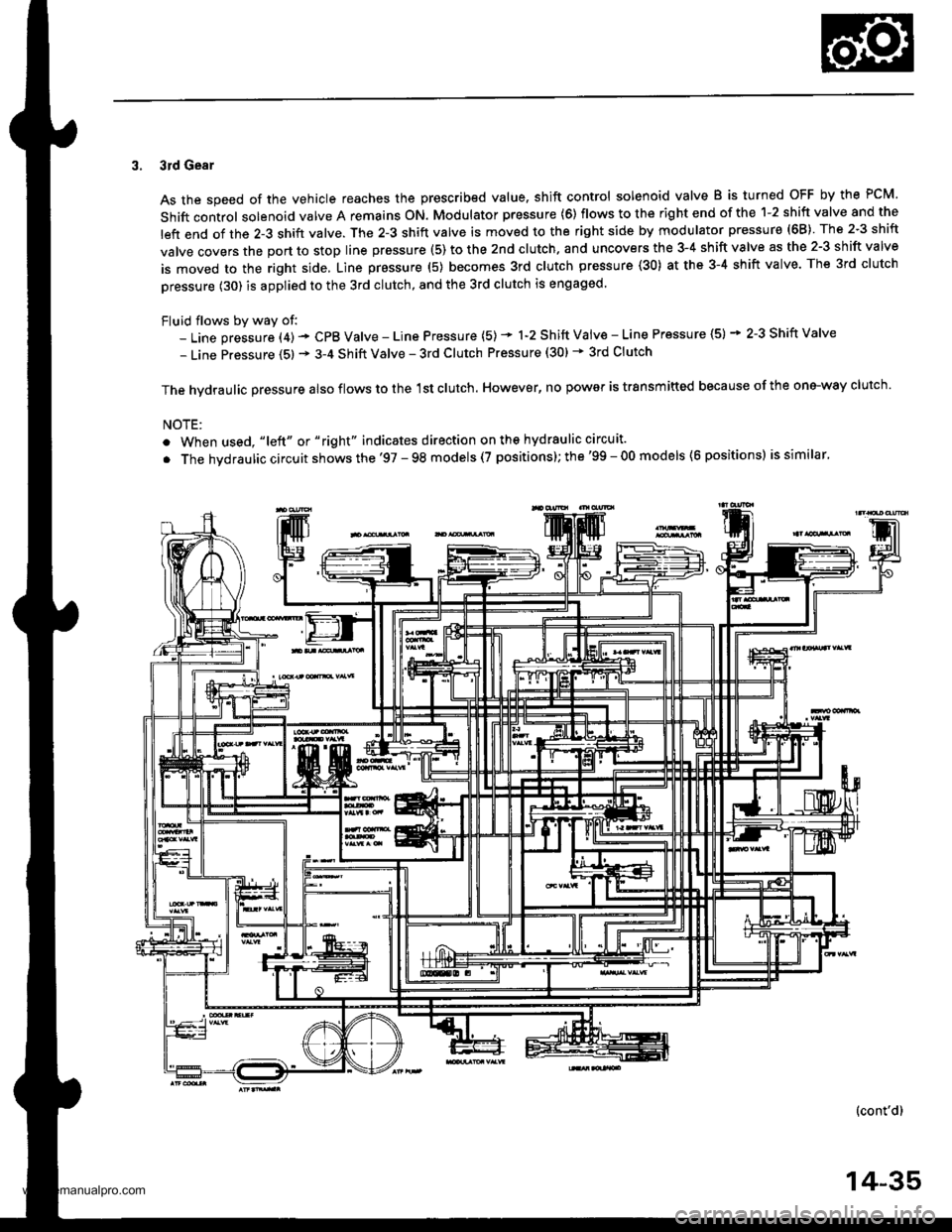
3. 3rd Gear
As the speed of the vehicle reaches the prescribed value. shift control solenoid valve B is turned OFF by the PCM.
Shift control solenoid valve A remains ON. Modulator pressure (6) flows to the right end of the 1-2 shift valve and the
left end of the 2-3 shift valve. The 2-3 shift valve is moved to the right side by modulator pressure (68) The 2-3 shift
valve covers the port to stop line prsssure (5) to the 2nd clutch. and uncovers the 3-4 shift valve as the 2-3 shift valve
is moved to the right side, Line pressure (5) becomes 3rd clutch pressure (30) at the 3-4 shift valve. The 3rd clutch
pressure (30) is applied to the 3rd clutch, and the 3rd clutch is engaged.
Fluid flows by way of:- Line pressure (4) - CPB Valve - Line Pressure (5) * 1-2 Shift Vaiv€ - Line Pressure (5) * 2-3 Shift Valve
- Line Pressure (5) * 3-4 Shift Valve - 3rd Clutch Pressure (30) * 3rd Clutch
The hvdraulic Dressure also flows to the 1st clutch. However, no power is trsnsmitted because of the one-way clutch.
NOTE:
. When used, "|eft" or "right" indicates direction on ths hydraulic circuit.
. The hvdraulic circuit shows the '97 - 98 models (7 positions); the'99 - 00 models (6 positions) is similar.
(cont'd)
14-35
www.emanualpro.com