abs HONDA CR-V 2000 RD1-RD3 / 1.G Repair Manual
[x] Cancel search | Manufacturer: HONDA, Model Year: 2000, Model line: CR-V, Model: HONDA CR-V 2000 RD1-RD3 / 1.GPages: 1395, PDF Size: 35.62 MB
Page 975 of 1395
![HONDA CR-V 2000 RD1-RD3 / 1.G Repair Manual
Troubleshooting
DTG 54: Main Relay
IWHT/GRNI
AAS CONTROL UNIT 26P CONNECTON
Wire side of female terminals
ABS COf{TROL UN]T 22P CONNECTOR
PCOMIGRN/WHTIscoM{BLK/WHTI
Wire side of female terminals
- Wi HONDA CR-V 2000 RD1-RD3 / 1.G Repair Manual
Troubleshooting
DTG 54: Main Relay
IWHT/GRNI
AAS CONTROL UNIT 26P CONNECTON
Wire side of female terminals
ABS COf{TROL UN]T 22P CONNECTOR
PCOMIGRN/WHTIscoM{BLK/WHTI
Wire side of female terminals
- Wi](/img/13/5778/w960_5778-974.png)
Troubleshooting
DTG 54: Main Relay
IWHT/GRNI
AAS CONTROL UNIT 26P CONNECTON
Wire side of female terminals
ABS COf{TROL UN]T 22P CONNECTOR
PCOMIGRN/WHTIscoM{BLK/WHTI
Wire side of female terminals
- With the ignition switch ON(lll, the ABS indicator doesnot go off.- With the SCS service connec-tor connected {see page 19-381,DTC 54 is indicatod.
Check the ABS +B 120 A) fuse inthe under-hood ABS luse/relaybox, and reinstall the fuse if it isoK.
FeDlace the tu3e and recheck.
Ch€ck tor an open in the 81, 82circuit:Measure the voltage betweenbody ground and the ABS controlunit 26P connector terminal No. 14and No. 15 individually.
Repair open in the wiro bstweonth6 ABS conirol unit and theunder-hood ABS fuse/rolay box,
ls there battery voltage?
Check for a short to body groundin the PMR circuit:L Turn the ignition switch OFF.2. Remove the pump motor relay.3. Disconnect the ABS controlunit 22P connector.4. Check lor continuity betweenterminal No. 19 and bodygrouno.
Repair short to body ground inthe wire betweon the under-hood ABS lGe/r.lay box and theABS control unit.
Check for a short to body groundin the PCOM, SCOM cilcuit:1. Disconnect the ABS controlunit 26P connector.2. Check tor continuity betweenbody ground and the ABS con-trol unit 26P terminals No- 1and No.2 individually.
. R€pair short to body ground inth€ P1COM circuit wire betweenthe ABS control unit and theund6r-hood ABS tuse/r6layoox.. R6p.ir short to body ground inthe PCOM or SCOM circuit wirebetweon th6 ABS control unitand lhe mod!lator unit.. R.Dlece tho modulrtor unit.(Short circuit inside the unitl
ls there continuity?
(To page 19-53)
www.emanualpro.com
Page 976 of 1395
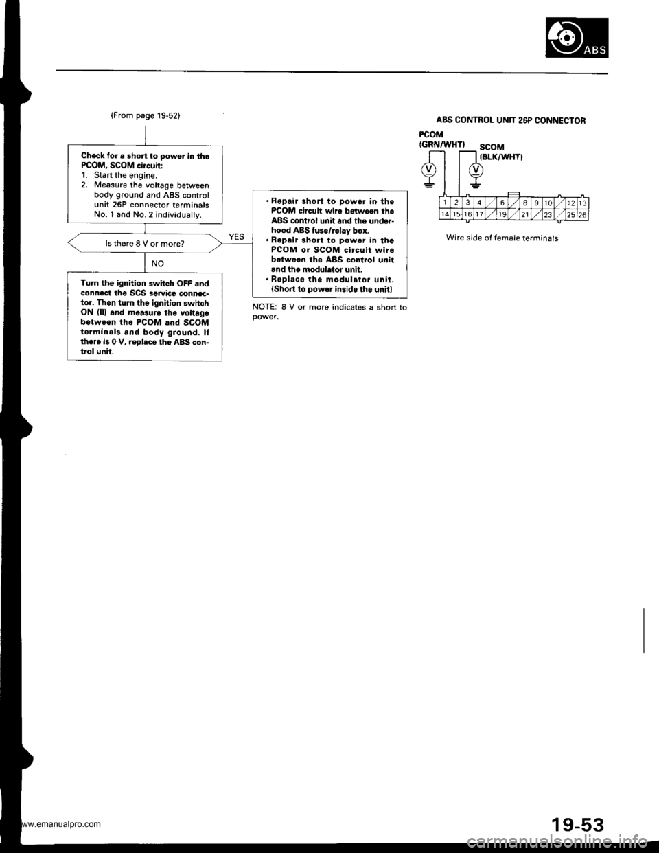
Check fo. a short to power in thaPCOM, SCOM circuhi1. Start the engine.2. Measure the voltage betweenbody ground and ABS controlunit 26P connector terminalsNo. I and No.2 individually.
'Repair short to powor in thsFCOM circuit wiro botwoon th€ABS control unit and the under-hood ABS tuse/r.lay box.. Repeir 3hort to power in thoPCOM or SCOM circuit wirebetwegn tho ABS control uniiand ths modulator unh,. R.placo tha modulatoi unit.(Shon to power in.ido th6 unitl
ls there 8 V or more?
Tu.n tho ignhion switch OFF andconnect thc SCS 3orvice connec-tor. Then turn thc ignition switchON (lll and measure tha voltagobotween the PCOM .nd SCOMtsrminal3 and body gJound. Itther6 is 0 V, .epleco tho ABS con-trol unit.
ABS CONTROL UNIT 26P CONNECTOR
PCOM
Wire side of temale terminals
NOTE: 8 V or more indicates a short to
(GRN/WHTI SCOM
www.emanualpro.com
Page 977 of 1395
Troubleshooting
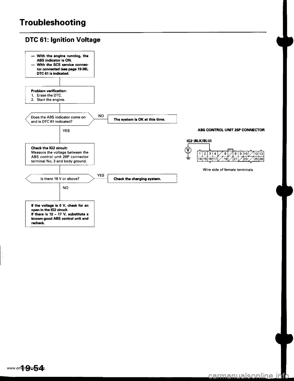
DTC 61: lgnition Voltage
- Whh the .ngine running. theABS indicator b ON,- With the SCS servicc connaetor connoctod {sao prgo 1998},DTC 61 b indi)atod.
Problom vorification:1. Erase the DTC.2. Start the engine.
Does the ABS indicator come onand is DTC 61 indicated?Tho ryrtom i. OK rt thb timo.
Ch.ck the lG2 circuit:Measure the voltage betweon theABS control unit 26P connectorterminal No.3 and body ground.
ls there 18 V or above?
lf the volt gc b 0 V, ch6d( to. anoD€n in lhe lG2 circuh.I thole ir 12 - 17 V, subatilui. !known-good ABS control unit .ndr€d|eck.
Wire side of temale termioals
www.emanualpro.com
Page 978 of 1395
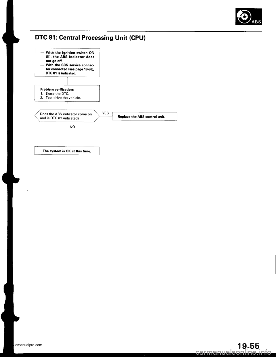
DTC 81: Central Processing Unit (CPUI
- with the ignition 3witch ON{ll}. the ABS indicator doesnot go off.- Whh the SCS sewice connec-tor connectod {see page 1938),DTC 81 b indicatod.
Problem vorific.tion:L Erase rne u t L.2. Test-drive the vehicle.
Does the ABS indicator come onand is DTC 81 indicated?R€place th. ABS control unit.
The system is OK at this time.
19-55
www.emanualpro.com
Page 979 of 1395
Modulator Unit
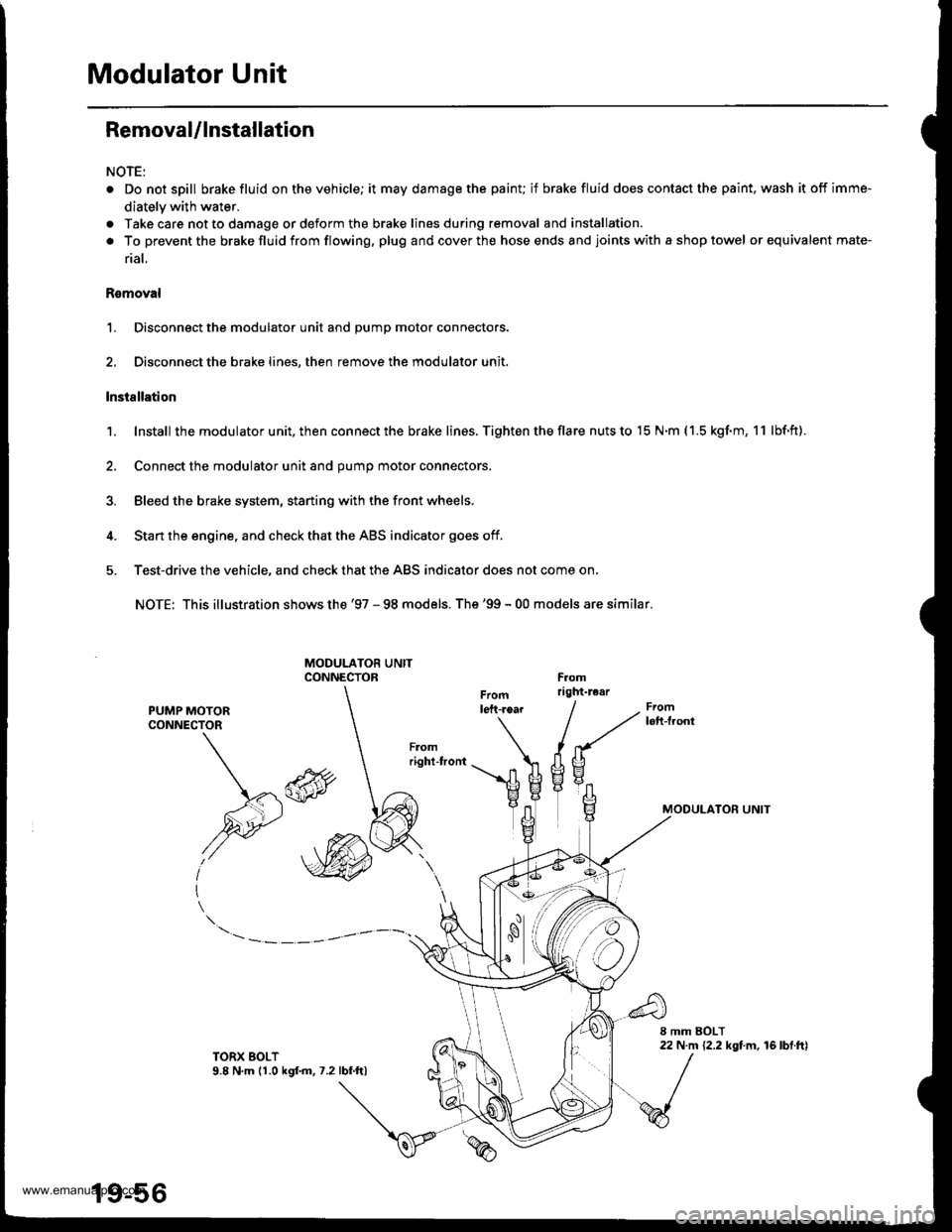
Removal/lnstallation
NOTE:
. Do not spill brake fluid on the vehicle; it may damage the painu if brake fluid does contact the paint, wash it off imme-
diately with water.
a Take care not to damage or deform the brake lines during removal and installation.
. To prevent the brakefluidfrom flowing, plug and coverthe hose ends and joints with a shop towel or equivalent mate-
rial,
Romoval
1. Disconnect the modulator unit and Dump motor connectors.
2. Disconnect the brake lines, then remove the modulator unit.
lnstallation
1. Install the modu lator u nit. then con nect the brake lines. Tighten the flare nuts to 15 N.m ( 1.5 kgf.m, 1 1 lbf.ft).
2. Connect the modulator unit and oumo motor connectors.
3. Bleed the brake system, staning with the front wheels.
4. Start the engine, and check that the ABS indicator goes off.
5. Test-drive the vehicle, and check that the ABS indicator does not come on,
NOTE: This illustration shows the '97 - 98 models. The'99 - 00 models are similar.
PUMP MOTORCONNECTOR
MODULATON UNIT\*\
,@
I
TORX EOLT9.8 N,m (1.0 kgf.m.7.2lbf ftl
19-56
www.emanualpro.com
Page 980 of 1395
ABS Control Unit
Pulsers/Wheel
Sensors
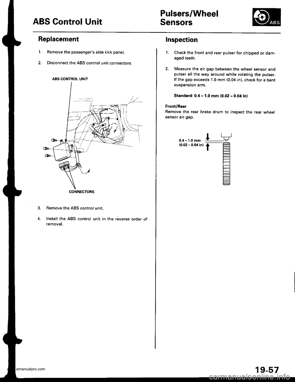
Replacement
Remove the passenger's side kick panel.
Disconnect the ABS control unit connectors.
Remove the ABS control unit.
Install the ABS control unit in the reverse order ofremovat.
ABS CONTROL UNIT
CONNECTORS
L
Inspection
1.Check the front and rear pulser for chipped or dam-
aged teeth.
Measure the air gap between the wheel sensor andpulser all the way around while rotating the pulser.
lf the gap exceeds 1.0 mm (0.04 in), check for a bentsusDension arm.
Standard: o.il - 1.0 mm 10.02 - 0.04 inl
Front/Rear
Remove the rear brake drum to insDect the rear wheolsensor air gap,
0.4 - 1.0 mm(0.02 - 0.04 inl
19-57
www.emanualpro.com
Page 1097 of 1395
Description
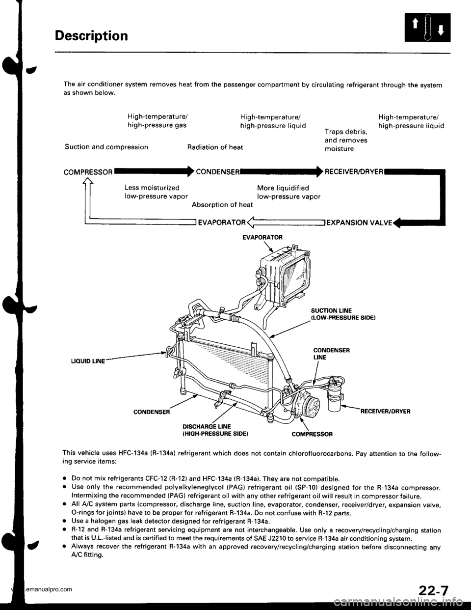
The air conditioner system removes heat from the passenger compartment by circulating refrigerant through the systemas shown below.
High'temperature/ High-temperature/
high-pressure gas h igh-pressure liquid
Suction and compression Radiation of heat
High-temperature/
high-pressu re liq uidr raps oeons,
and removes
motsture
More liquidified
row-pressure vapor
EVAPoRAToR (-l EXPANSToN vAL
SUCTION LINEtLow-PRESSURE S|OEt
LIOUID LINE
CONDENSER
coMpREssoR Il- coruoerusenl* necetve
Less moisturized
low-pressure vapor
Absorption of heat
DISCHARGE LINEIHIGH.PRESSURE SIDEI
This vehicle uses HFC-I34a (R-l34a) refrigerant which does not contain chlorofluorocarbons. Pay attention to the follow-ing service items:
. Do not mix refrigerants CFC-12 (R-12) and HFC-l34a (R-134a). They are not compatible.. Use only the recommended polyalkyleneglycol (PAG) refrigerant oil (SP-10) designed for the R-134a compressor.Intermixing the recommended (PAG) refrigerant oil with any other refrigerant oil will result in compressor failure.. Afl Ay'C system parts (compressor, discharge line. suction line, evaporator, condenser. receiver/dryer, expansion valve,O-rings for joints) have to be proper for refrigerant R-134a. Do not confuse with R-12 parts.
. Use a halogen gas leak detector designed for refrigerant R-134a.. R-12 and R-134a refrigerant servicing equipment are not interchangeable. Use only a recovery/recycling/charging stationthat is U.L.iisted and is certified to meet the requirements of SAE J2210 to service R-134a air conditioning system.. Always recover the refrigerant R-134a with an approved recovery/recycling/charging station before disconnecting anylVC fitting.
EVAPORAYOR
22-7
www.emanualpro.com
Page 1144 of 1395
A/C Service Tips and Precautions
The air conditioner system uses HFC-'134a (R-134a) refrigerant and polyalkyleneglycol {PAG) refrigerant oil*, which are not
compatible with CFC-12 (R-12) refrigerant and mineral oil. Do not use R-12 refrigerant or mineral oil in this system, and do
not attempt to use R-12 servicing equipmenu damage to the air conditioner system or your servicing equipment will
resutr.
*KEIHIN SP-10:
. P/N 38897 - Pl3 - A01AH: 120 m{ (4 fl.oz, il.2 lmp.oz)
. P/N 38899 - Pl3 - A01: 40 mf 11113tl.oz,1.4 lmp.oz)
Use only service equipment that is U.L.-listed and is certified to meet the requirements of SAE J2210 to remove R-134a
from the air conditioner system,
CAUTION: Exposure to air conditioner refrigerant and lubricant vapor or misl can irritats eyes, nose and throat. Avoid
breathing the air conditioner refrigerant and lubricant vapor or mist,
lf accidental system discharge occurs, ventilate work area before resuming service.
R 134a service equipment or vehicle air conditioner systems should not be pressure tested or leak tested with compressed
air.
E@ Some mixtures of air and R-13,1a have been shown to be combustible at elevat€d pressures and can result
in fire or explosion causing iniury or property damage. Never use complessed air to pressure test R-l3,[a service equip-
ment or vehicle air conditioner systems.
Additional health and safety information may be obtained from the refrigerant and lubricant manufacturers.
1. Always disconnect the negative cable from the battery whenever replacing air conditioning parts.
2. Keep moisture and dust out of the system. When disconnecting any lines, plug or cap the fittings immediately; don't
remove the caps or plugs until just before you reconnect each line.
3. Before connecting any hose or line. apply a few drops of refrigerant oilto the O-ring,
4. When tightening or loosening a fitting, use a second wrench to support the matching fitting.
5. When discharging the system, use a R l34a refrigerant recovery/recycling/charging station; don't release refrigerant
into the atmosphere.
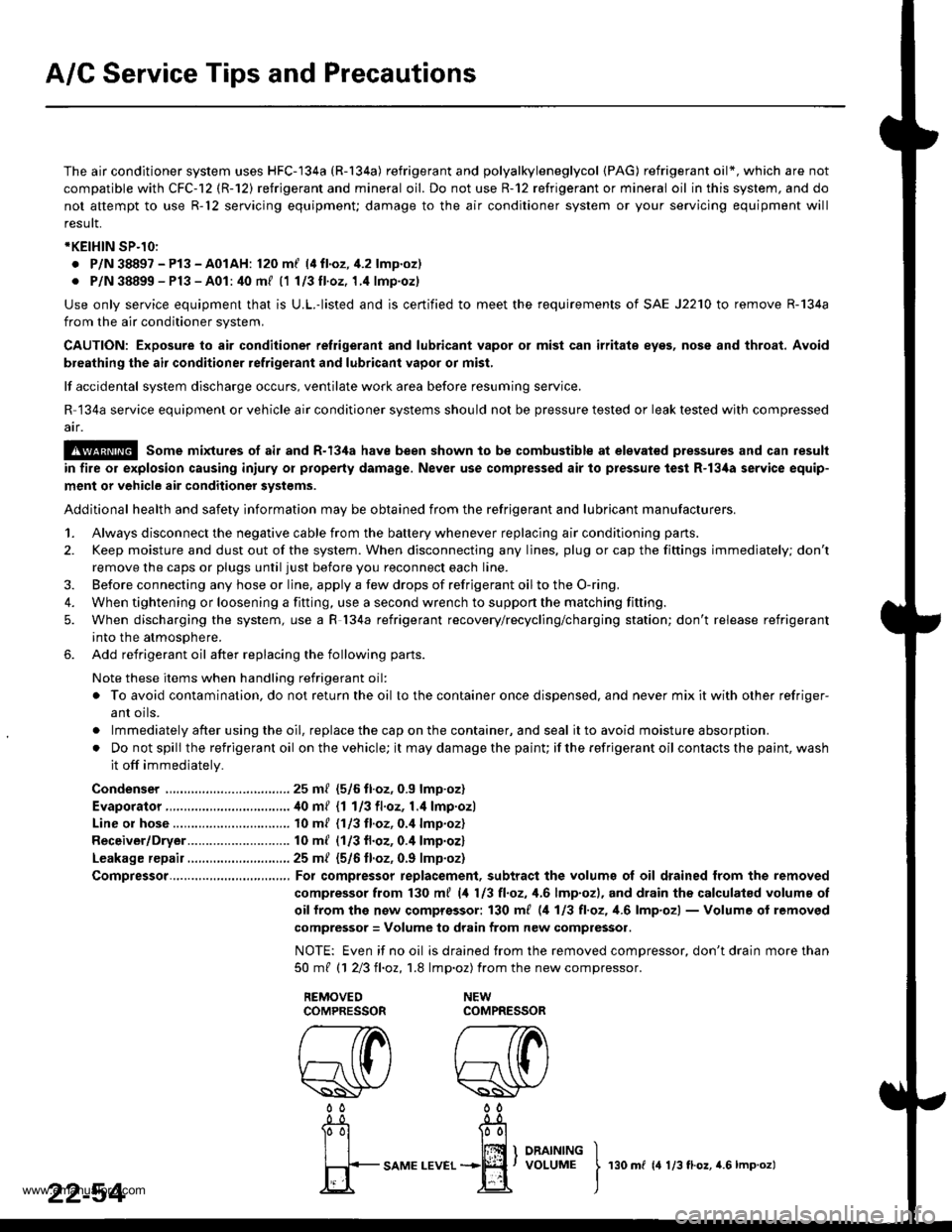
6. Add refrigerant oil after replacing the following parts.
Note these items when handling refrigerant oil:
o To avoid contamination, do not return the oil to the container once dispensed, and never mix it with other refriger-
ant oils.
. lmmediately after using the oil, replace the cap on the container, and seal it to avoid moisture absorption.
. Do not spill the refrigerant oil on the vehicle; it may damage the painu if the refrigerant oil contacts the paint, wash
it off immediately.
Condenser . 25 ml (5/6 tl.oz, 0.9 lmp.oz)
Evaporator.,................................40 m/ 11 113ll.oz,l.4 lmp.ozl
Line or hose ........... 10 ml (1/3 fl.oz, 0.4 lmp.oz)
Receiver/Dryer....... 10 ml (1/3 fl.oz, 0.4 lmp.oz)
Leakage repair............................ 25 m/ (5/6 ll.oz, 0.9 lmp.oz)
Compressor.......,..., For compressor replacement, subtract the volumg ol oil drained from the removed
compressor from 130 m{ (4 113 tl.oz, 1,6lmp.ozl, and drain the calculatsd volume of
oif from the now comprossor: 130 ml (,1 113 tl,oz, 1.6lmp'ozl - Volume of removed
compressor = Volume to drain from new compressor.
NOTE: Even if no oil is drained trom the removed compressor, don't drain more than
50mt 11 213ll,oz,1.8 lmp.oz) from the newcompressor.
22-54I
rso m r rr:0.o., r.s r-o.o.t
www.emanualpro.com
Page 1161 of 1395

Body Electrical
Speciaf Toofs ,...,..,.............-.23-2
Troubleshooting
Tips and Precautions ......,.,..........,.................. 23-3
Five-step Troubleshooting ........,.,.,...,,.,......... 23-5
Wire Color Codes ...,....,.. 23-5
Relay and Control Unit Locations
Engine Compartment ..,.,......,......................... 23-6
Dashboard ,.,.,..............-.- 23-7
Door ....................... .........23-10
Index to Cilcuits and Sysiems
Accessory Socket .. ,....,.,..,.,. 23-95*Airbags ................ .,....,. Sestion 24
Air Conditioning ,.,.,.... Section 22
Alternator ................... Section 4
Anti-lock Brake System {ABSI ................... Section 19'A/T Gear Position Indicator ....................... Section 1,1
Automatic Transmission System ...........,.. Section 14
Battery ................... ..............23-50
Blower Controls .,...,.,, Section 22
Charging System ....... Seqtion il
Clock -'98 Model ................ 23-98
Connector ldentification and Wire HarnessRouting .................. ......... 23.11
Cruise Control ............ Ssction 4
Dash Lights Brightness Contlo||er ..................... 23-90
Fan Conlrols ...,......,.... Section 10
Fuel Pump ,..,.,...,....,.... Section 11
Fuses...................... .,,.,.,.,.,,.,23-40*Gauges
Circuit Diagram ......-....-..23-58
Fuel Gauge .....,.,..... Section 11
Speedometer ..,..........,... 23-56
Ground Distribution ,....,.,...23-46
Hatch Glsss ODenor .........................,.,.,.,.,..,.,.,.,,. 23-121
Heater Controls .-........ Soction 21*Horns.,...,..,.,.,....... ................23"104*fgnition Switch ,,.,.,..,.,.,,.,.,.,23-51
lgnition Key Light System -'97 Mod6l .............. 23.88
-+
BODY
www.emanualpro.com
Page 1164 of 1395
Troubleshooting
Tips and Precautions (cont'dl
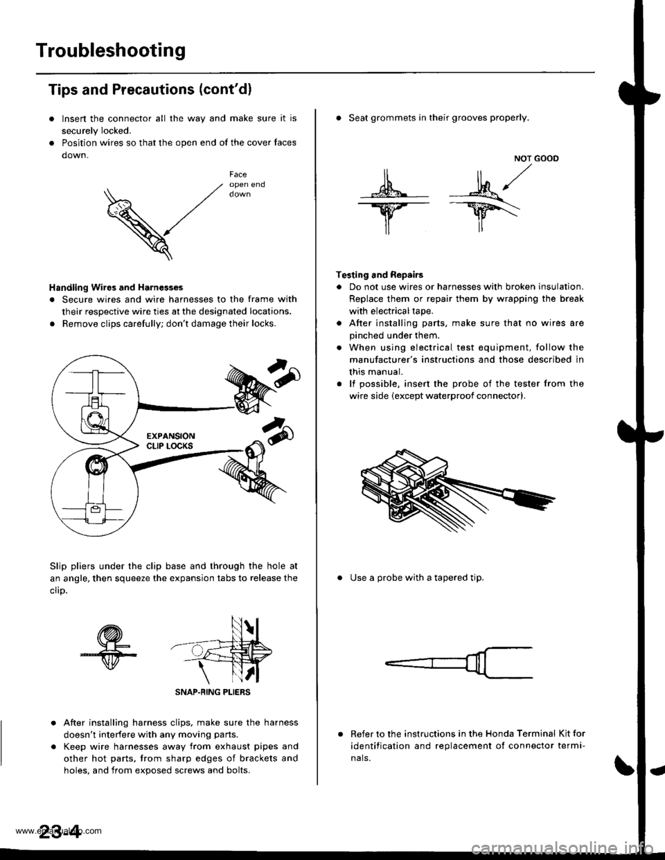
Insen the connector all the way and make sure it is
securely Iocked.
Position wires so that the open end of the cover faces
down.
V
Faceopen end
Handling Wires and Harnesges
. Secure wires and wire harnesses to the frame with
their respective wire ties at the designated locations.
. Remove clips carefully; don't damage their locks.
Slip pliers under the clip base and through the hole at
an angle, then squeeze the expansion tabs to release the
clrD.
After installing harness clips, make sure the harness
doesn't interfere with any moving pans.
Keep wire harnesses away from exhaust pipes and
other hot parts, trom sharp edges of brackets and
holes. and from exoos€d screws and bolts.
NOT GOOD
A -M/
lr lr*
T€sting and Repairs
. Do not use wires or harnesses with broken insulation.
Replace them or repair them by wrapping the break
with electricaltape.
. After installing parts, make sure that no wires are
pinched under them.
. When using electrical test equipment, follow the
manufacturer's instructions and those described in
this manual.
. lf possible, insert the probe of the tester from the
wire side (except waterproof connector).
. Seat grommets in their grooves properly.
. Use a probe with a tapered tip.
Refer to the instructions in the Honda Terminal Kit for
identification and replacement of connector termi-
nals.
www.emanualpro.com