dashboard HONDA CR-V 2000 RD1-RD3 / 1.G Repair Manual
[x] Cancel search | Manufacturer: HONDA, Model Year: 2000, Model line: CR-V, Model: HONDA CR-V 2000 RD1-RD3 / 1.GPages: 1395, PDF Size: 35.62 MB
Page 1330 of 1395
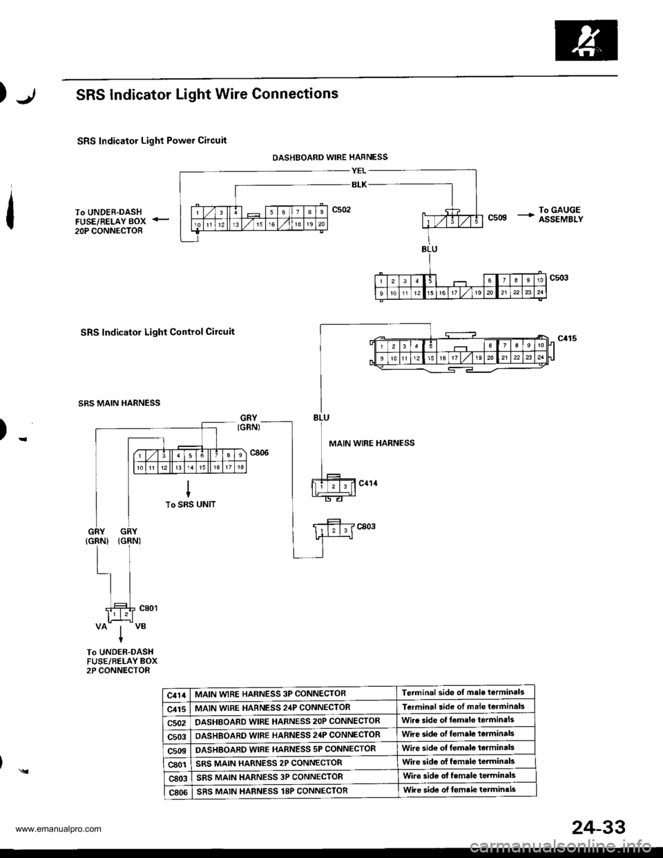
SRS Indicator Light Wire Connections
SRS Indicator Light Power Circuit
DASHBOARD WIRE HARNESS
YEL
BLK
To UNDER-DASHFUSE/RELAY BOX <_
20P CONNECTOR
To GAUGEcsog + assEMBLy
SRS Indicator Light Control Circuit
SRS MAIN HARNESS
)-MAIN WIRE HARNESS
VAIVBIt
To UNDER-DASHFUSE/BELAY BOX2P CONNECTOR
c414MAIN WIRE HARNESS 3P CONNECTORTerminal side of msle t€rminals
c415MAIN wlRE HARNESS 24P CONNECTORTerminal aide of male terminals
c502DASHBOARD WIRE HARNESS 2OP CONNECTORWire side of lemslo terminsls
c503OASHBOARD WIRE HARNESS 24P CONNECTORWire side of female t€rminal3
c509DASHBOABD WIRE HARNESS 5P CONNECTORWire sid€ ot lemale te.minals
c801SRS MAIN HARNESS 2P CONNECTORwire side ol f.male terminals
c803SRS MAIN HARNESS 3P CONNECTORWire side ol female terminals
c806SRS MAIN HARNESS T8P CONNECTORWire side of lomrle terminals
)
24-33
www.emanualpro.com
Page 1332 of 1395
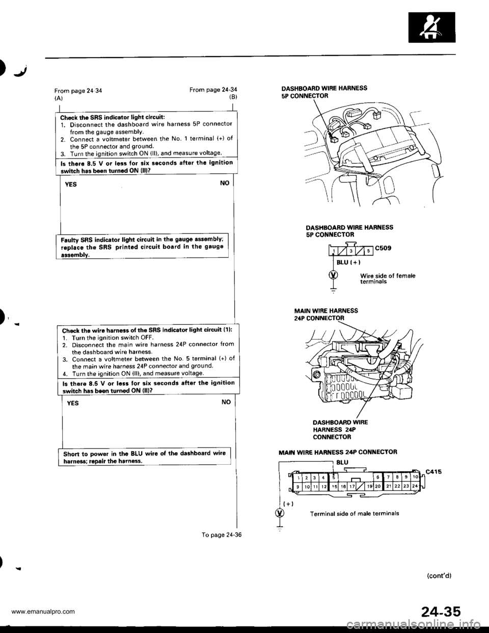
Chock th6 SRS indic.lor light circuit:1. Disconnect the dashboard wire harness 5P connector
from the gauge assembly.2. Connect a voltmeter between the No l terminal (+) o{
the 5P connector and grouncl.
3. Turn the ignition switch ON {ll), and measure voltage
ls thero 8.5 V or lats for 3ix second! aflsr the ignition
switch ha3 bo€n turnod ON (ll)7
YESNO
Fdulty SRS indicator light cilctlit in ths gauge sssomblY;
replaco tho SRS printod circuit board in the gauge
aasombly,
Chock th6 wire harn.$ of the SRS indicstor light circuh (11:
1. Turn the ignition switch OFF.2. Disconnect the main wire harness 24P connector from
the dashboard wire harness-3. Connect a voltmeter between the No 5 terminal (+) of
the ma;n wire harness 24P connecior and ground
4. Turn the ignition ON {ll), and measure voltage.
ls there 8,5 V or l€r3 tor six s€cond3 efter the ignilion
switch has bssn turnod ON llll?
YESNO
Short to powor in the BLU wire of tho dashbosrd wire
harne3s; Epait the harne3.s.
To page 24-36
Jt)
From page 24 34(A)From page 24-34(8)DASHBOARD WIRE HARNESS
5P CONNECTOR
DASHBOARD WIRE HARI{ESS5P CONI{ECTOR
c509
Wire side ol femaleterminals
)_
DASHBOARO WIREHARNESS 24PCONNECfOR
(cont'd)
MAIN WIRE HARNESS
MAIN WIRE HARI{ESS 2/tP COI{ ECTOR
Terminal side of male terminals
24-35
www.emanualpro.com
Page 1335 of 1395
Troubleshooting
The SRS Indicator Light Doesn't Go Off - '97 model (cont,d)
From page 24 37(A)
SRS MAIN HARNESS 18P CONNECTOR
(B)To page 24'39
DASHBOARD WIRE HARNESS5P CONNECTOR
(c)To page 24-40
DASHBOAND WIRE HARI{ESS5P CONNECTOR
)
J
c509
Wire side ol femaleterminals
T
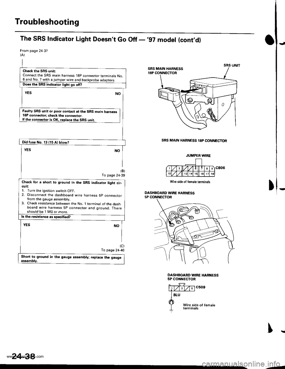
Check the SRS unit:Connect the SRS main harness 18P connector terminals No.6 and No.7 with a jumper wire and backprobe
Faulty SRS unit or poo. contact at the SRS main ha.ness18P connectoi; check the connector.lfthe conneqtor is OK, replace the SRS unit.
Oid tuse No. 13 (15 Al blow?
Check for a short to ground in the SRS indicator tight cir-cutl:1. Turn the ignitlon switch oFF.2, Disconnect the dashboard wire harness 5p connectorfrom the gauge assembly.3. Check resistance between the No. 1 terminal ofthe dashboard wire harness 5P connector and ground. Thereshould be 1 MO or more.
Shon to ground in th6 gaugo assembly; replaco the gau96
JUMPER WIRE
Wlre sido ot tomale terminsls
243a
--
www.emanualpro.com
Page 1336 of 1395
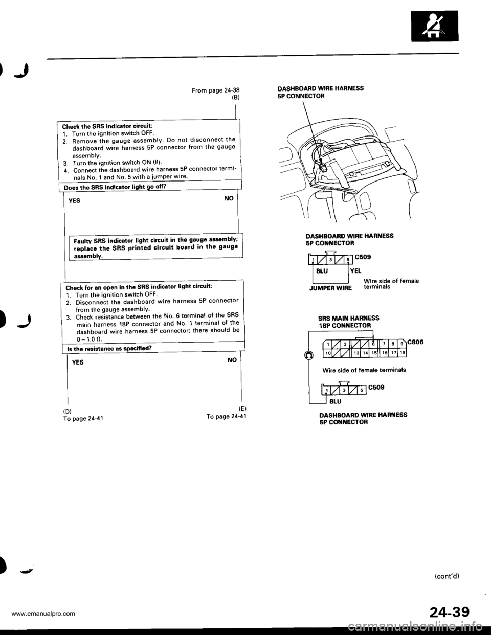
Check lhe SRS indicalor circuit:
1. Turn the ignition switch OFF
2. Remove the gauge assembly Do not disconnect the
dashboard wire harness 5P connector from the gauge
assemoly.3. Turn the ignition switch ON (ll).
4. Connect tie dashboard wire harness 5P connector termi-
nals No. I and No 5 with a iumper wire.
Does the SRS indicator light 90 otn
Faulty SRS indicator light circuit in the 9aug6 a$embly;
reolace the SRS printod circuit boa.d in th' gauge
Check tor rn open in the SRS indicator light circuit:
1. Turn the ignition switch OFF
2. Disconnect the dashboard wire harness 5P connector
from the gauge assemblY.
3. Check res]sta-nce between the No. 6 terminal ol the SRS
main harness 18P connector and No l terminal ol the
dashboard wire harness 5P connector; there should be
From page 24-38{B)
DASHBOARD WIRE HARNESS5P CONNECTOR
DASHBOARD WIRE HARNESS5P CONI{ECTOR
)
Y;yfivvcsosffi
I BLU IYELWir6.side of femaleJUMPER WIRE lormrna|s
SRS MAI HAN ESSt8P CO I{ECTOR
DASHBOARD WIRE HARNESS5P COI{NECTOR
{D)To page 24-41
1E)To page 24-41
)(cont'd)
Wire side oI fsmale terminals
24-39
www.emanualpro.com
Page 1337 of 1395
Troubleshooting
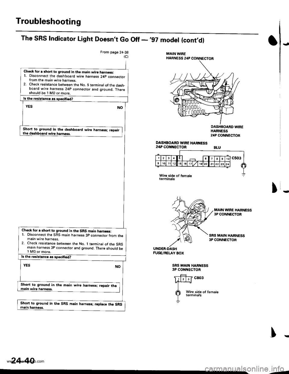
The SRS Indicator Light Doesnt Go Off -'97 model {cont'dl
From page 24-38
1C)
Check for a short to ground in tho main wire ha.n.3s:1. Disconnect the dashboard wire harngss 24p connectorfrom the main wire harness,2. Check resistance between the No. 5 terminal of the dash_board wire harness 24P connector and ground. Thereshould be 1 M0 or more.
Short to ground in tho deshbosrd wire harne.r; raD.irthe dashboard wiro harness.
Check tor a short to ground in tho SRS main hfina3!:1. Disconnect the SBS main harness 3p connector from themaan wire harness.2. Check resistance between the No. 1 terminal of the SRSmain harness 3P connector and ground. There should be1 MO or more.
Short to ground in tho main wire harnesr; ,opair th6main wire hamoss.
Short to ground in the SRS main hsrn6sa;.oplac. thc SRSmain harn6ss.
i,
MAIN WIREHARNESS 24P CONNECTOR
DASHBOARD WIRE HAff{ESS24P COi{NECTOR
OASHBOARD WIREHARNESS24P CONNECTOR
BLU
)
MAIN wlRE HARNESS3P CONNECTOB
SRS MAIN HARNESS3P CONNECTOR
UNDER.OASHFUSE/RELAY BOX
SRS MAII{ HARI{ESS3P CONNECTOR
cao3
)r
24-40
Wire side of femalet6rminals
-1
www.emanualpro.com
Page 1338 of 1395
)
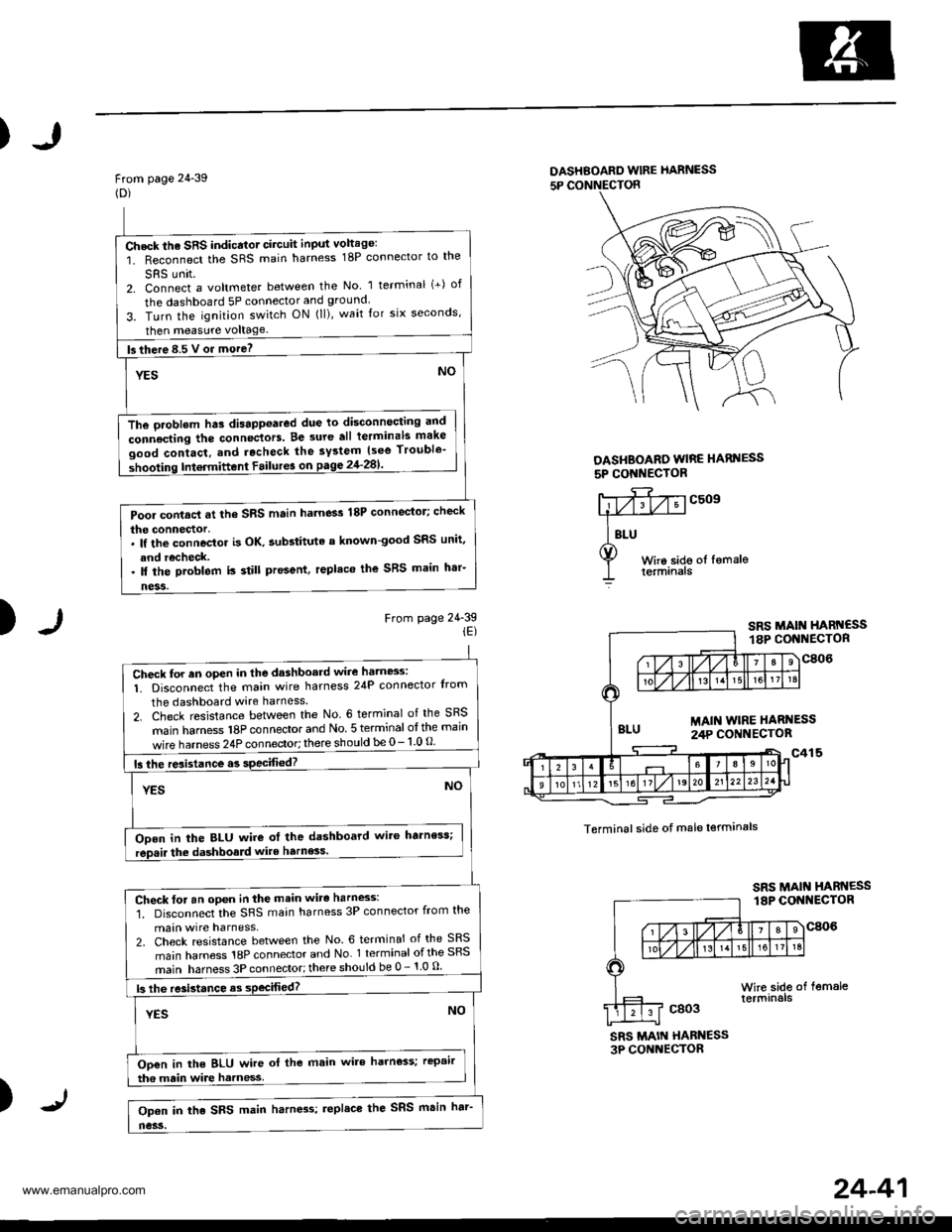
From page 24-39(D)
DASHBOARD wlRE hARNESS
5P CONNECTON
DASHBOARO WIRE HARI{ESS
5P CONI{EC'OR
)From page 24-39iE)
c509
Terminal side of male lerminals
SRS MAIN HABN€SS3P CONNECTOR
)
Check the SRS indicator circuit input voltage:
1. Reconnect the SRS main harness 18P connector to the
SRS unit2. Connect a voltmeter between the No 1 terminal (+) of
the dashboard 5P connector and ground.
3. Turn the ignition switch ON (ll), wait for six seconds,
then measure voltage
fs there 8.5 V or more? -
YESNO
The oroblem hts disappoared due to disconnocting and
connecting the connectors. Be 3ure all terminals make
good contact, and rocheck the system {see Trouble'
shooting Intermittent Failur6 on pagg 2'l-281'
Pool contacl at the SRS main harness 18P connector; check
the connector.. lf the connoctor is OK. aubstituta a known-good SRS unit,
and recheck.. ll the problem is still present, replaco the SRS main h'r-
ness.
Check for an oPen in the dashboard wire hatn8s:
1. Disconnect the main wire harness 24P connector Irom
the dashboard wire harness
2. Check resistance between the No. 6 terminal of the SRS
main hamess 18P connector and No 5 terminal otthe main
wire harness 24P connector; there should be 0- 1 0 O
15 the resistance.s specified?
YESNO
ODen in the BLU wire ot the dashboard wit6 harness;
rep.ir the dashboald wite harness.
Check for an open in the main wirc harness:'1. Disconnect the SRS main harness 3P connector from the
main wire harness,2. Check resistance between the No. 6 terminal of the SRS
main harness 18P connector and No 1 terminal ofthe SRS
main harness 3P connector;there should be 0 - 1 0 u
|3 lhe re3istance as sPecifiod?
YESNO
Oo€n in the BLU wire ol the main wire harness; rcpair
tha main wire harness
Op€n in the SRS main harn4s; replace the SRS msin har'
no3s.
24-41
www.emanualpro.com
Page 1340 of 1395
)
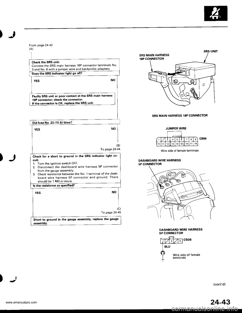
Ftom page 24-42(A)
SRS MAIN HARNESS 18P CONNECTOR
)
1B)fo page 24-44
(c)
To page 24-45
Wire side of lemale lerminals
DASHBOAED WIRE HARNESS5P CONNECTOR
DASHEOARD WIRE HARNESS5P CONNECTOR
c509
)(cont'd)
SRS UNIT
SRS MAIN HARNESS
Check the SRS unit:Connect the SRS main harness 18P connector terminals No.
3 and No. 6 with a iumper wire and backprobe
Does the SRS indicator light go otf?
Faulty SRS unit or poor contact at the SRS main harness
18P connedor; check the connector.lf the connoctor is OK, replace the SRS unit
Did tuse No. 23 {10 A} blow?
Check for a short to ground in the SRS indicator light cir-
curl:1. Turn the ignition switch OFF.
2, Disconnect the dashboard wire harness 5P connector
from the gauge assembly,3. Check resistance between the No l terminal ofthedash-
board wire harness 5P connector and ground. There
should be 1 Mo or more.
Short to ground in the gauge assembly; replace the gauge
JUMPER WIRE
24-43
www.emanualpro.com
Page 1341 of 1395
Troubleshooting
The SRS Indicator Light Doesn't Go Off -'99 - 00 models (cont,d)
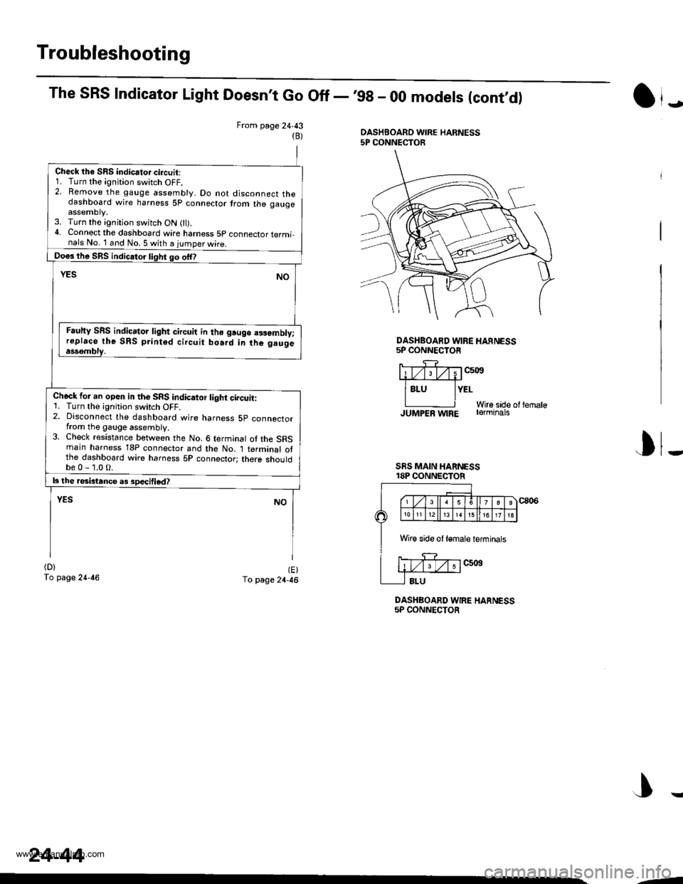
From page 24,43DASHBOARD WIRE HARNESS5P CONNECTOR(B)
Check the SRS indicator circuit:1. Turn the ignition switch OFF.2. Remove the gauge assembly. Do not disconnect thedashboard wire harness 5p connector trom the gaugeassemDty.3. Turn the ignition switch ON 0l).4. Connect the dashboard wire hamess 5p connector terminals No. 1 and No. 5 with a iumoer wire.
Doos lhe SRS indic.tor light go offl
YESNO
Fauhy SRS indic.tor light circuit in lho gruge a3samblv;replaco the SRS print6d circuit bo.rd in the g.ugeassombly.
Check for an opeo in the SRS indicaior light circuit:1. Turn the ignition swirch OFF.2. Disconnect the dashboard wire harness 5p connectorfrom the gauge assembly.3. Check resistance between the No. 6 terminal of the SRSmain haroess 18P connector and the No. 1 terminal otthe dashboard wire harness 5P connector; there shouldbe0-1.0O.
|3 the rosbtance a3 sDecified?
YESNO
(D)
To page 24-46(E)To page 24-46
DASHBOARD WIRE HARNESS5P CONNECTOR
J
DASHBOARD WIRE HANNESS5P CONNECTOR
liTv;Tv;1c5i0s#
lsru lYErWire sade ol lernaleJUMPER w|RE rerminats
I
SRS MAIN HARNESS18P CONNECTOR
J
Wir€ side ot lemale ieminals
24-44
,-
www.emanualpro.com
Page 1342 of 1395
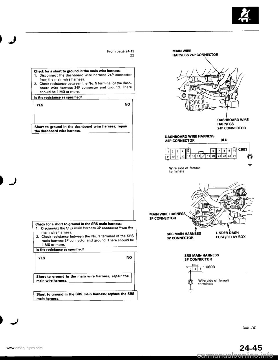
Chock fo. a short to glound in tho main wire harn63:
1. Disconnect tho dashboard wire harnoss 24P connector
from the main wire harness.2. Check resistance between the No 5terminal oIthedash-
board wire harness 24P connector and ground. There
should bs 1 Mo or more.
Short to ground in tho dashboatd wilo harnots; repair
Chcck for a short to ground in the SRS main harnoss:
1. Disconnect the SRS main hart\ess 3P connector {rom the
main wire harness,2. Check resistance between the No. 1 terminal of the SRS
main harness 3P connector and ground. There should be
1 MO or more.
Short to ground in the mlin wire harnoss; .epair lh€
mlin wira harness.
Short to ground in thc SRS mtin hemess; replace tho SRS
J
From page 24-431C)
MAIN WIREHABNESS 2,lP CONNECTOR
OASHBOARD WIRE HARI{ESS
24P CONNECTOR
OASHBOARD WIREHARNESS2,rP CONNECTOR
BLU
)
MAIN WIRE3P CONNECTOR
cToR FUSE/RELAY BOX
SRS MAIN HARNESS3P CONIIECTOR
c803
)(cont'd)
24-45
www.emanualpro.com
Page 1343 of 1395
Troubleshooting
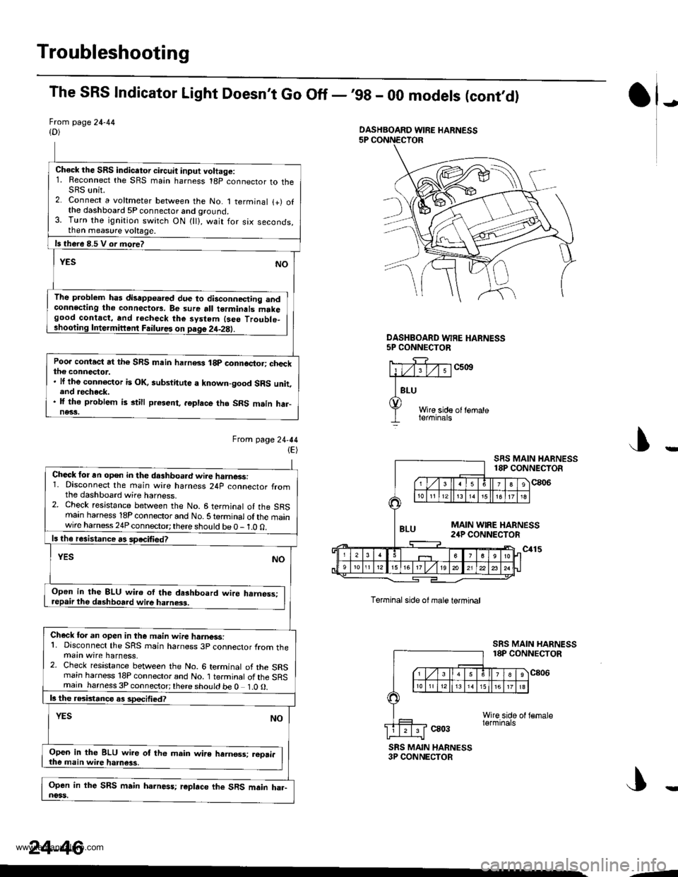
The SRS Indicator Light Doesn't Go Off -,99 - 00 models (cont,d)
Frcm page 24-44{D)
Ch€ck the SRS indicator circuit input voltage:1. Reconnect the SRS main harness 18p connector to theSRS unit.2. Connect a voltmeter between the No. 1 terminal {+) ofthe dashboard 5P connector and ground.3. Turn the ignition switch ON {ll}, wait for six seconds,then measure voltage.
ls there 8.5 V or more?
YESNO
The problem has disapp€ared due to disconnecting andconnecting tho connectors. Be sure all terminals makegood contact, and .echeck the system {seo Troublo_shooting Intermiftent Failures on page 2it-2E).
Poo. contact at the SRS main harn8s 18p connector; checkthe connector.. lf the connoctor is OK, aubstitute a known-good SRS unit,end recheck.. lf the problem is still present, .6place tho SRS m.in har-ne33.
Ftom lage24-44(E)
J)
DASHEOARD WFE HARNESS5P CONNECTOR
c5ott
Wire side of lemaleterminals
J
Torminal side ol male termtnal
ca03
SRS MAIN HARNESS18P CONNECTOR
c806
SRS MAIN HARNESS3P CONNECTOR
DASHBOARD WIRE HARNESS
Check for an open in the dashboa.d wire harnessi1. Disconnect the main wire harness 24p connector fromthe dashboard wire harness.2. Check resistance between the No. 6 terminal of the SRSmain harness 18P connector and No. S te.minal of the mainwire harness 24P connector; there should be 0 - 1.0 0.
ls th€ resistance rs speciliedT
YESNO
Open in the 8LU wi.o ol the dashboard wire hrmess:repair the dashboard wire ha.ness.
Check fo. an open in the m.in wire hamess:1. Disconnect the SRS rnain harness 3p connector from themain wire harness,2. Check resistance between the No. 6 terminal of the SRSrnain harness 18P connector and No. 1 terminal of the SRSmain harness 3P connector;there should be 0 1.0O.
b the rGbtanco as sDecified?
NOYES
Open in the BLU wir6 of th6 main wire hernos3; reori.the main wire hamess,
Open in the SRS main harness; r€place the SRS main ha.-noss.
24-46
--
www.emanualpro.com