Bleeding HONDA CR-V 2000 RD1-RD3 / 1.G Workshop Manual
[x] Cancel search | Manufacturer: HONDA, Model Year: 2000, Model line: CR-V, Model: HONDA CR-V 2000 RD1-RD3 / 1.GPages: 1395, PDF Size: 35.62 MB
Page 189 of 1395
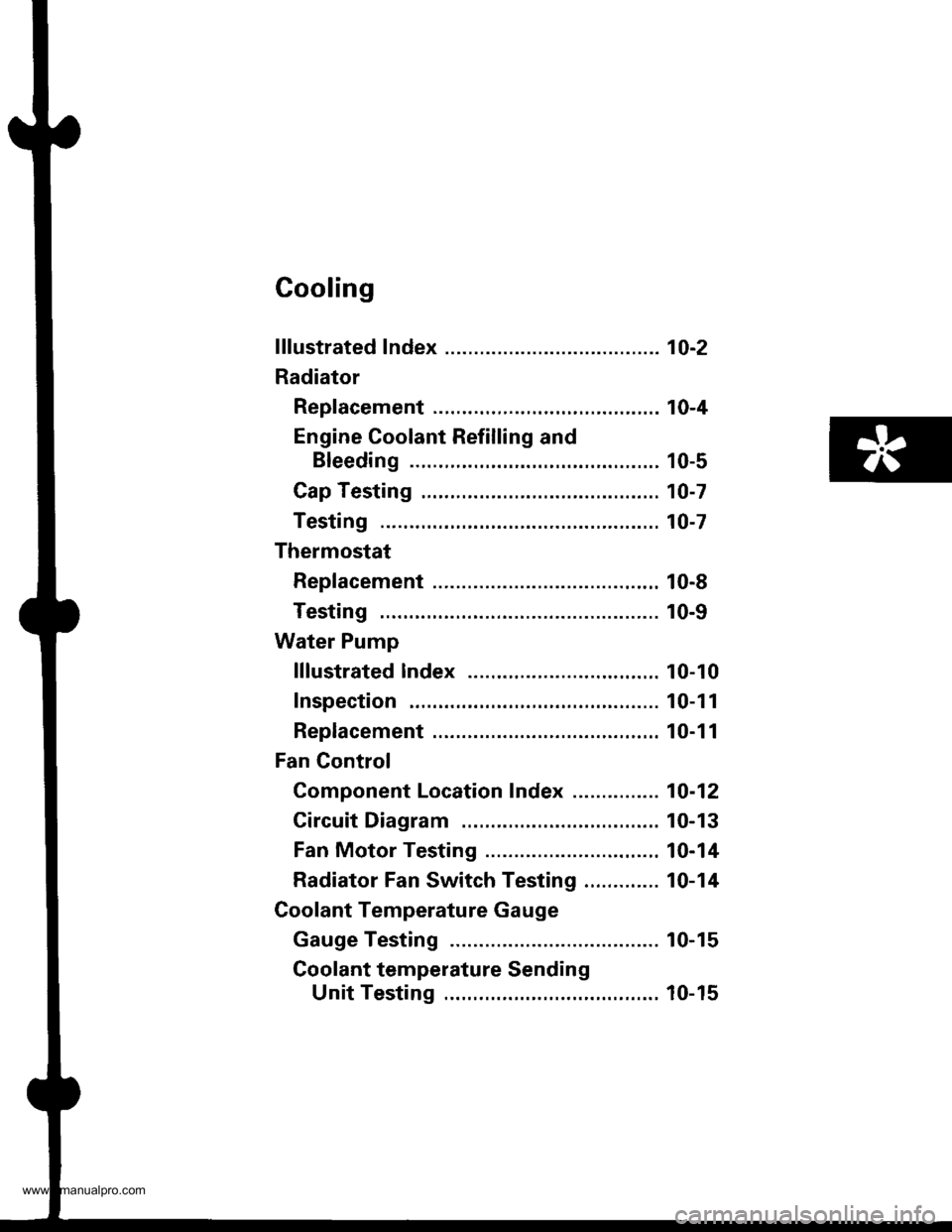
Cooling
f ffustrated Index ........... ..... 1O-2
Radiator
Rep|acement ...........,....,...................... 10-4
Engine Coolant Refilling and
Bleeding ..,.,................. 10-5
Cap Testing .................... 10-7
Testing ......10-7
Thermostat
Rep|acement ....................................... 10-8
Testing ...... 10-9
Water Pump
lllustrated lndex ....,..... .. 10-10
Inspection . 10-1 1
Replacement ....................................,.. 10-1 1
Fan Gontrol
Component Location Index ............... 10-12
Circuit Diagram ............. 10-13
Fan Motor Testing ......... 10-14
Radiator Fan Switch Testing ............. 10-14
Coolant Temperature Gauge
Gauge Testing ............... 10-15
Coolant temperature Sending
Unit Testing ........,....... 10-15
www.emanualpro.com
Page 190 of 1395
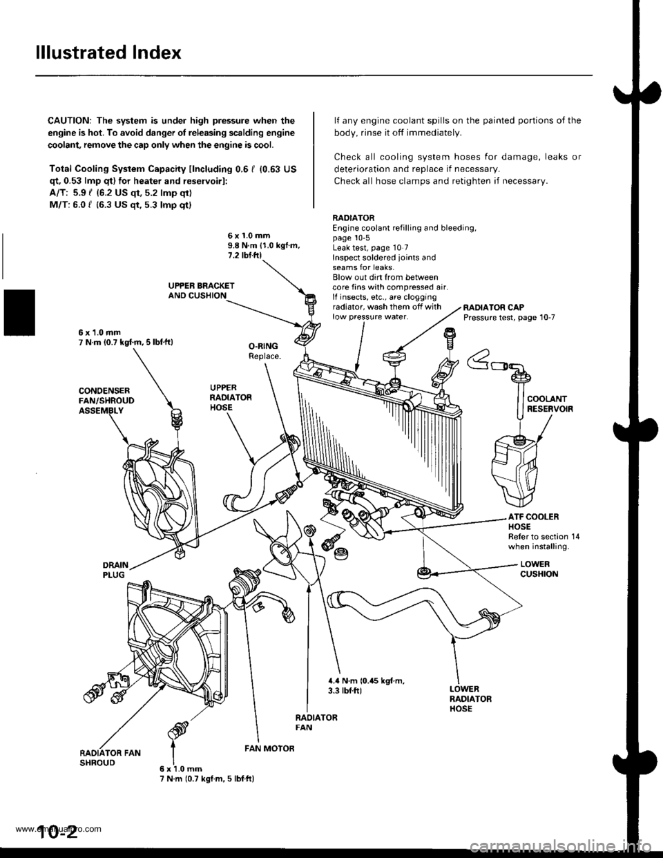
lllustrated Index
CAUTION: The system is under high pressure when the
engine is hot. To avoid danger ol releasing scalding engine
coolant, remove the cap only when the engine is cool.
Total Cooling System Capacity fincluding 0.6 I (0.63 US
qt, 0.53 lmp qt) for heater and reservoirl:
A/T: 5.9 { {6.2 US qt, 5.2 lmp qt)
M/T: 6.0 f (6.3 US $, 5.3 lmp qt)
deterioration and replace if necessar,.
Check all hose clamps and retighten if necessary.
lf any engine coolant spills on the
body, rinse it off immediately.
Check all cooling system hoses
painted portions of the
for damage, leaks or
6x1.0mm9.8 N.m 11.0 kgf.m.1.2 tbl.ftl
RADIATOREngine coolant refilling and bleeding,page 10-5Leak test, page 10 7Inspect soldered joints andseams for leaks.Blow out din from betweencore fins with compressed air.lf insects, etc., are cloggingradiator, wash them off withlow pressure water.RADIATOR CAPPressure test, page 10-7
ATF COOLERHOSEReler to section 14when installing.
LOWERcusHroN
6x1.0mm7 N.m (0.7 kgf.m, 5 lbf ftl
FAN MOTOR
10-2
www.emanualpro.com
Page 193 of 1395
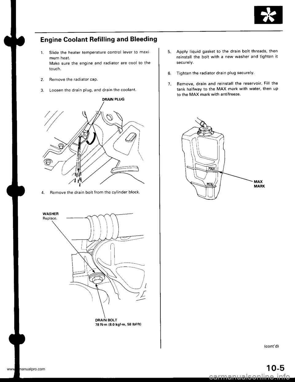
Engine Coolant Refilling and Bleeding
1. Slide the heater lemperature control lever to maxi
mum heat.
Make sure the engine and radiator are cooi to the
touch.
2. Remove the radiator caP.
3. Loosen the drain plug, and drain the coolant.
4. Remove the drain bolt from the cylinder block.
DRAIN PLUG
DRAIN BOLT78 N.m {8.0 ksl.m, 58 lbtft}
10-5
6.
7.
Apply liquid gasket to the drain bolt threads, then
reinstall the bolt with a new washer and tighten it
securely.
Tighten the radiator drain plug securely.
Remove, drain and reinstall the reservoir' Fill the
tank halfway to the MAX mark with water, then up
to the MAX mark with antitreeze.
(cont'd)
www.emanualpro.com
Page 194 of 1395
Radiator
Engine Coolant Refilling and Bleeding (cont'dl
Mix the recommended antifreeze with an equal
amount of water in a clean container.
NOTE:
. Always use Genuine Honda Antifreeze/Coolant.
Using a non-Honda coolant can result in corro-s\on, ca
sng t\e coo\
g sys\em \o ma\lunct\on
o. fail.
For best corrosion protection, the coolant con-
centration must be maintained year-round at50% minimum. Coolant concentrations less than
50% may not provide sufficient protection against
corrosion or freezing. Coolant concentrationsgreater than 60% will impair cooling efficiency
and are not recommended.
Do not use additional rust inhibitors or anti-rustproducts; they may not be compatible with the
coolant.
Engine Coolant Refill Capacity Iincluding 0.6 / 10.63US $, 0.53 lmp qtl for hoater and ressrvoirl:
A/T: 3.9 f {4.1 US $, 3.4 lmp qtl
M/T: 1.O t 14.2 US $, 3.5 lmp qrl
10-6
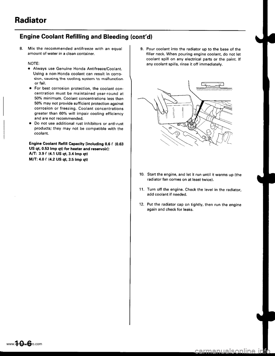
9. Pour coolant into the radiator uD to the base of the
filler neck. When pouring engine coolant. do not let
coolant spill on any electrical pans or the paint. lf
any coolant spills, rinse it oft immediately.
Start the engine, and let it run until it warms up (the
radiator fan comes on at least twice).
Turn off the engine. Check the level in the radiator,
add coolant if needed.
Put the radiator cap on tightly. then run the engine
again and check for leaks.
11.
10.
12.
www.emanualpro.com
Page 925 of 1395
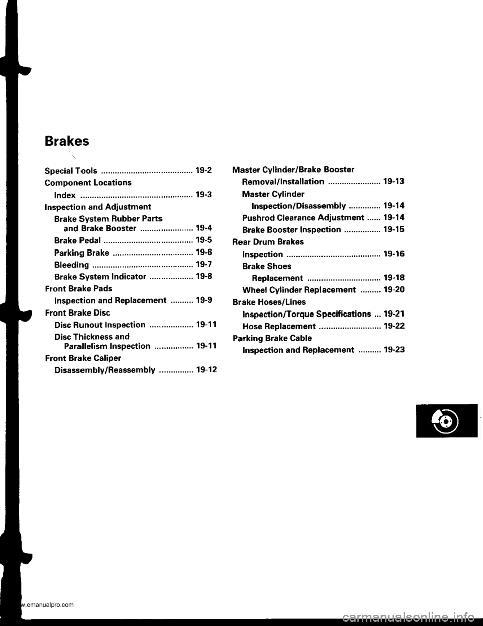
Brakes
Special Tools ............. 19-2
Component Locations
lndex ................ ...... 19-3
Inspection and Adlustment
Brake System Rubber Parts
and Brake Booster ..........,,,.......... 19-4
Brake Pedal ............ 19-5
Parking Brake ........ 19-6
Bleeding ................. 19'7
Brake System Indicator ................... 19-8
Front Brake Pads
Inspection and Replacement .......... 19-9
Front Brake Disc
Disc Runout Inspection ................... 19-11
Disc Thickness and
Parallelism Inspection ........,........ 19-1 1
Front Brake Caliper
Disassembly/Reassembly ............... 19-12
Master Cylinder/Brake Booster
Removal/lnstallation ....................... 19-13
Master Cylinder
Inspection/Disassembly .............. 19-14
Pushrod Clearance Adiustment ...... 19-14
Brake Booster Inspection ...,.,,,,....... 1 9-1 5
Rear Drum Brakes
Inspection .............. 19-15
Brake Shoes
Replacement ..... 19-r 8
Wheel Cylinder Replacement ......... 19-20
Brake Hoses/Lines
Inspection/Torque Specifications ... 19-21
Hose Replacement ....,...,............. ..,,, 19-22
Parking Brake Cable
Inspection and Replacement .......... 19-23
www.emanualpro.com
Page 931 of 1395
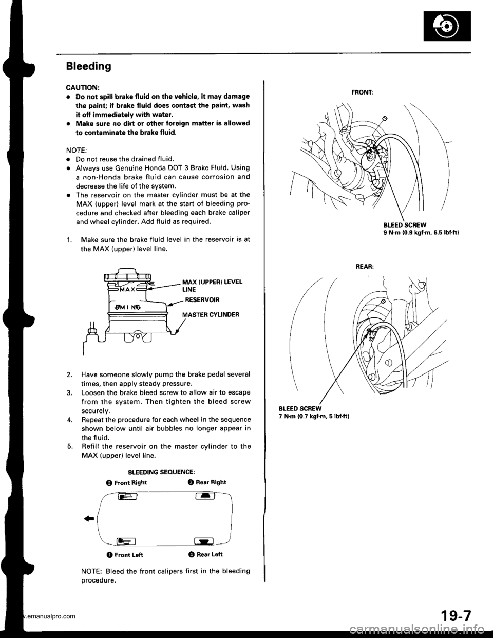
Bleeding
CAUNON:
. Do not spill brake tluid on the vehicle. it may damage
the paint; if brake fluid does contaqt th€ paint, wash
it otf immodiately with water.
. Maks sure no dirt oy other forsign matter is allowsd
to contaminate the brake fluid.
NOTE:
. Do not reuse the drained fluid.
. Always use Genuine Honda DOT 3 Brake Fluid. Using
a non-Honda brake fluid can cause corrosion and
decrease the life of the svstem.
. The reservoir on the master cylinder must be at the
MAX (upper) level mark at the start of bleeding pro-
cedure and checked after bleeding each brake caliper
and wheel cylinder. Add fluid as required.
1, Make sure the brake fluid level in the reservoir is at
the MAX (uDDer) level line.
MAX {UPPER) LEVELLINE
RESERVOIR
MASTER CYLINDER
2.
3.
Have someone slowly pump the brake pedal several
times, then apply steady pressu.e.
Loosen the brake bleed screw to allow air to escape
from the system. Then tighten the bleed screw
securely.
Repeat the procedure for each wheel in the sequence
shown below until air bubbles no longer appear in
the tluid.
Refill the reservoir on the master cvlinder to the
MAX (upper) level line.
ALEEDING SEOUENCE:
O Front RightGt Rear Right
O Front LeflO Rear Left
NOTE: Bleed the front calipers first in the bleeding
procedure.
4.
FRONT:
BLEEO SCREW7 N.m (0.? kgf.m, 5 lbf.ftl
19-7
www.emanualpro.com
Page 952 of 1395
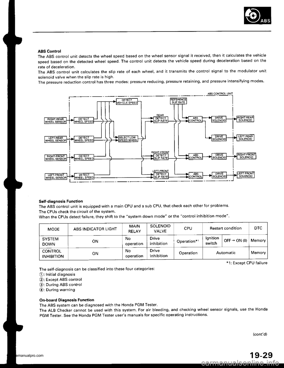
ABS Control
The ABS control unit detects the wheel speed based on the wheel sensor signal it received, then it calculates the vehicle
speed based on the detected wheel speed. The control unit detects the vehicle speed during deceleration based on the
rate of deceleration.
The ABS control unit calculates the slip rate of each wheel, and it transmits the control signal to the modulator unit
solenoid valve when the slip rate is high
The pressure reduction control has three modes: pressure reducing, pressure retaining, and pressure intensi{ying modes.
Self-diagnosis Function
The ABS control unit is equipped with a main cPU and a sub cPU, that check each other for problems.
The CPUs check the circuit of the system.
When the CPUS detect failure, they shift to the "system down mode" or the "control inhibition mode".
The self-diagnosis can be classitied into these four categories:
O: Initial diagnosis
O: Except ABS control
O; During ABS control
@: During warning
On-board Diagnosis Function
The ABS system can be diagnosed with the Honda PGM Tester.
The ALB Checker cannot be used with this system. For air bleeding. and checking wheel sensor signals, use the Honda
PGIM Tester. See the Honda PGM Tester user's manuals for specific operating instructions.
(cont'd)
19-29
ABS CONTROL I-INIT
MODEABSINDICATOR LIGHTMAIN
RE LAY
SOLENOID
VALVERestan conditionDTC
SYSTEM
DOWNONNo
operatron
Drive
inhibitionOperation*rlgnition
switchOFF - oN (ll)Memory
CONTROL
INHIBITIONONNo
operaton
Drive
inhibitionOperationAutomaticlVemory
*1: Except CPU failure
www.emanualpro.com
Page 960 of 1395
Kickback'1. The motor operates when the ABS is functioning. and the fluid in the reservoir is forced out to the master cylinder,
causing kickback at the brake pedal.
2. The ABS control unit operates the solenoid valve when the brake pedal is released after the initial diagnosis You may
hear the solenoid valve operate at this time, but it is normal
Pumo Motol
1. The pump motor operates when the ABS is functioning
2. The ABS control unit checks the pump motor operation during acceleration. You may hear the motor operate at this
time, but it is normal.
Brake Fluid Replacement/Ail Bleeding
L Brake fluid replacement and air bleeding procedures are the same as for vehicles without ABS To ease bleeding, start
with the front wheels.
Troubleshooting
1. The troubleshooting flowchart procedures assume that the cause of the problem is still present and the ABS indicator
is still on. Following the flowchart when the ABS indicator does not come on can result in incorrect diagnosis.
2. Ouestion the customer about the conditions when the problem occurred, and try to reproduce the same conditions
for troubleshooting.
Self-diagnosis is made at various times such as the initial diagnosis, except ABS control, during ABS control, during
acceleration, during the specified vehicle speed, etc. Therefore, the symptom canngt be checked unless the check
conditions match with the problem conditjons
3. When the ABS jndicator does not come on during the test-drive. but troubleshooting is performed based on the DTC,
check lor loose connectors, poor contact of the terminals, etc., before you start troubleshooting.
4. After troubleshooting, erase the DTC and test-drive the vehicle. Be sure the ABS indicator does not come on.
5. The connector illustratjons show the female terminals with a single outline and the male terminals with a double out-
l ne.
ABS Function Test
To simulate ABS operation and activate the solenoid valves and pump, use the Honda PGM Tester.
Connect the PGM Tester to the 16P Data Link Connector (DLC). When the System Select menu is displayed, select the ABS
Test Mode menu, and follow the tester's prompts.
19-37
www.emanualpro.com