Front damper HONDA CR-V 2000 RD1-RD3 / 1.G Workshop Manual
[x] Cancel search | Manufacturer: HONDA, Model Year: 2000, Model line: CR-V, Model: HONDA CR-V 2000 RD1-RD3 / 1.GPages: 1395, PDF Size: 35.62 MB
Page 818 of 1395
DriveshaftsFront Driveshafts
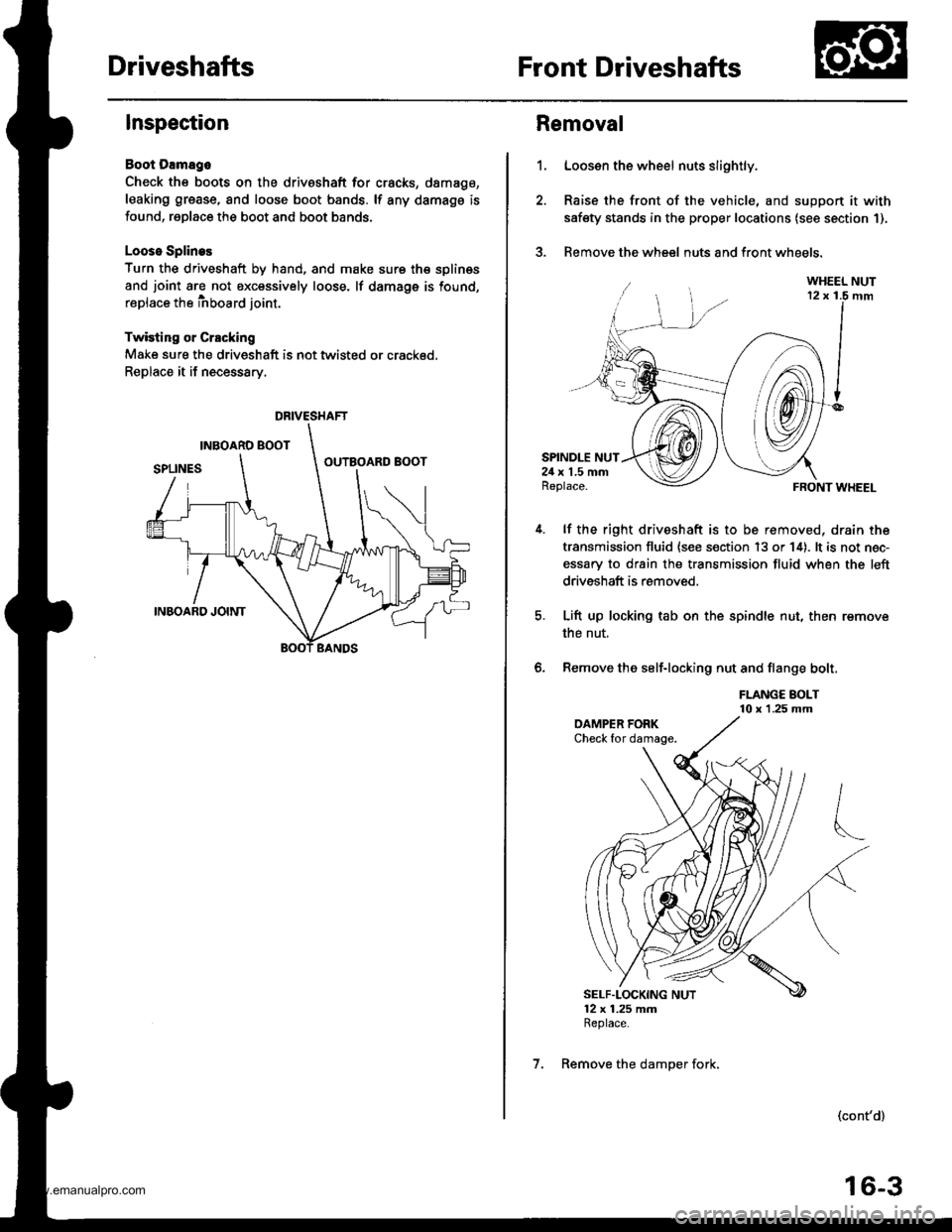
Inspection
Boot Damago
Check the boots on the driveshaft for cracks, damago,
leaking grease, and loose boot bands. lf any damags is
found, replace the boot and boot bands.
Looso Splines
Turn the driveshaft by hand, and make sure th€ splin€s
and joint are not excessively loose. lf damage is found,
replace the inboard joint.
Twisting or Crscking
Make sure the driveshaft is not twisted or crackod.
Replace it if necessary.
DRIVESHAFT
1.
Removal
Loosen the wheel nuts slightly.
Raise the front of the vehicle, and suppon it with
safety stands in the proper locations (see section 1).
Remove the wheel nuts and front wheels.?
SPINDLE NUT24 x 1.5 mmReplace.
lf the right driveshaft is to be removed, drain the
transmission fluid {see s€ction 13 or 14). lt is not nec-
essary to drain the transmission fluid when the left
driveshaft is removed.
Lift up locking tab on the spindle nut, then remove
the nut,
Remove the self-locking nut and flange bolt,
FLANGE BOLT10 x 1.25 mm
FRONT WHEEL
(cont'd)
6.
SELF"LOCKING NUT12 x 1.25 mmReplace.
7. Remove the damper fork,
16-3
www.emanualpro.com
Page 821 of 1395
Front Driveshafts
Disassembly (cont'd)
Double Loop
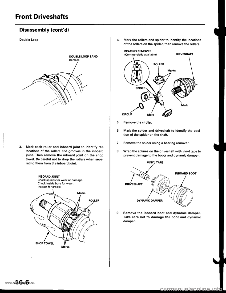
Mark each roller and inboard joint to identify the
locations of the rollers and grooves in the inboardjoint. Thon remove the inboard ioint on the shop
towel. Be careful not to drop the rollers when sepa-
rating them from the inboard joint.
INBOARD JOINTCheck splines for wear or damage.Check inside bore for wear.Inspect for cracks.
16-6
4, Mark the rollers and spider to identify the locstions
of the rollers on the sDider, then remove the rollers.
BEARING REMOVER(Commercially available) DRIVESHAFT
Remove the circlip,
Mark the spider and driveshaft to identify the posi-
tion ofthe spider on the shaft.
Remove the spider using a bearing remover,
Wrap the splines on the driveshaft with vinyl tape to
prevent damage to the boots and dynsmic damper,
7.
q
INBOARD BOOT
DRIVESHAFT
DYNAMIC DAMPER
Rsmove the inboard boot and dvnamic
Take care not to damage the boot and
damDer.
damper.
dynamic
DRIVESHAFT
Mark
www.emanualpro.com
Page 823 of 1395
![HONDA CR-V 2000 RD1-RD3 / 1.G Workshop Manual
Front Driveshafts
parts with solvent.
o *4@] :Thoroughly pack the inboard and outboard joints and both joint boots with the joint grease included in the
new driveshaft set.. The98 Canada model andal](/img/13/5778/w960_5778-822.png "HONDA CR-V 2000 RD1-RD3 / 1.G Workshop Manual
Front Driveshafts
parts with solvent.
o *4@] :Thoroughly pack the inboard and outboard joints and both joint boots with the joint grease included in the
new driveshaft set.. The98 Canada model andal")
Front Driveshafts
parts with solvent.
o *4@] :Thoroughly pack the inboard and outboard joints and both joint boots with the joint grease included in the
new driveshaft set.. The'98 Canada model andall '99 - 00 models use a TPE (Thermoplastic Polyester E lastomer) outboard joint boot.
Use the ear clamp type boot band in the outboard boot set.
Grease quantity:
Inboard Joint: All models 120 - 130 g (i1.2 - 4.6 oz)
Left inboard joint splines (Al: 0.5 - 1.0 g (0.018 - 0.035 oz)
Outboard Joint: '97 model and'98 USA model 130 - 140 g (4.6 -,1.9 oz)'98 Canada model and all '99 - 0O models 140 - 150 g 14.9 - 5.3 oz)
Reassembly
Note these items during reassembly
. Clean the disassembled parts with solvent, anddry them thoroughly with compressed air. Do not wash the rubber
INBOARO JOINT
SPIOERINBOARD BOOT
SET RINGReplace.
LEFT INBOAROJOINT
SPLINES: (Al-6rPack cavity with grease.
wtn grease.
BANDS
DYNAMIC DAMPER
STOP RINGReplace.
OUTBOARD BOOT
EAR CLAMPReplace.
ITPE)*I
-611
-/ Pack cavity with grease.
DOUELEReplace.BAND+'BAND*1
__G1Pack cavitywrtn grease.
OUTBOARD BOOT*'(RUBBERI
-GrjPack cavity*l: '98 Canada models, all '99-00models
*2: '97 - 98 models (except'98 Canada model)
16-8
wtrn grease.
www.emanualpro.com
Page 825 of 1395
Front Driveshafts
Reassembly {cont'd)
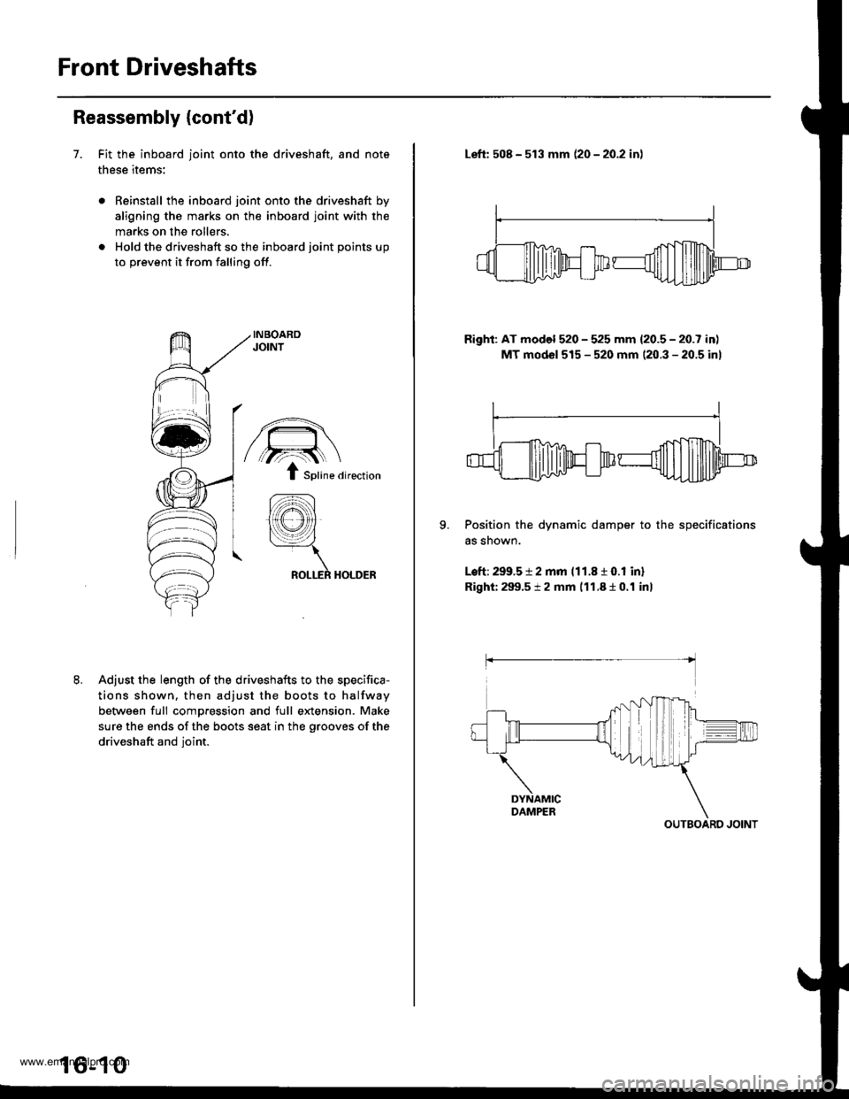
7. Fit the inboard joint onto the driveshaft, and note
these items:
Reinstall the inboard joint onto the driveshaft by
aligning ths marks on the inboard joint with the
marks on the rollers.
Hold the driveshaft so the inboard joint points up
to prevent it from falling off.
Adjust the length of the driveshafts to the specifica-
tions shown. then adjust the boots to halfway
between full compression and full e)dension. Make
sure the ends of the boots seat in the grooves of the
driveshaft and Ioint.
/€\
/,?:..{ \
t Sptine airection
lffi
tYl:\
ROLLER HOLDER
16-10
Left: 508 - 513 mm 120 - 2O.2 inl
Right: AT model 520 - 525 mm {20.5 - 20.7 in)
MT mod6l 515 - 520 mm (20.3 - 20.5 inl
II
-flm+dm@
9. Position the dynamic damper to the specifications
as snown.
Left: 299.5 t 2 mm 111.8 r O.l inl
Right: 299.5 t 2 mm 111.810.1 inl
OUTBOARO JOINT
www.emanualpro.com
Page 826 of 1395
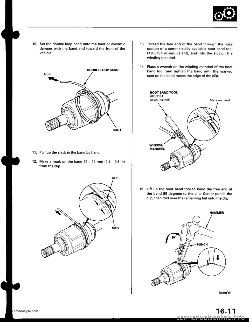
10. Set the double loop band onto the boot or dynamic
damper with the band end toward the front of the
vehicle.
11. Pull up the slack in the band by hand.
12. Make a mark on the band 10 - 14 mm (0.4 - 0.6 in)
from the clip.
OOUBLE LOOP BAND
CLIP
13.
'14.
Thread the free end of the band through the nose
section of a commercially available boot band tool(KD-3191 or equivalent). and into the slot on the
winding mandrel.
Place a wrench on the winding mandrel of the boot
band tool. and tighten the band until the marked
spot on the band meets the edge of the clip.
BOOT BAND TOOL(KD-3191
or equivalentlMark on band.
15.
WINDINGMANDREL
Lift up the boot band tool to bend the free end of
the band 90 degrees to the clip, Center-punch the
clip, then fold over the remaining tail onto the clip.
(cont'd)
16-1 1
HAMMER
www.emanualpro.com
Page 833 of 1395
Front DriveshaftsIntermediate Shaft
Installation {cont'd}
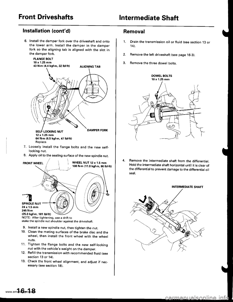
Install the damper fork over the driveshaft and ontothe lower arm. Install the damper in the damperfork so the aligning tab is aligned with the slot inthe damper fork.
FLANGE BOLT10 x 1.25 mm€ N.m {4.i1kst.n,32 lbf.ftl ALtcNtNG TAB
12x 1.25 mm64 N.m {6.5 kgf.m, 47 lbf.ftlReplace.
7. Loosely install the flange bolts and the new self-locking nut.
8. Apply oil to the seating surface of the new spindle nut.
FRONT WHEELi WHEEL NUT 12 x 1.5 mm108 N.m (11.0 kgf.m,80lbf.ftl
SPINDLE NUT24 x 1.5 mm245 N.m{25.0 ksf.m, 181 lbf.ft)NOTE: Atter tightening. use a drift tostake the spindle nut shoulder against the driveshaft.
9. Install a new spindle nut, then tighten the nut.10. Clean the mating surfaces of the brake disc and thewheel. then install the front wheel with the wheelnuts,
1'1. Tighten the flange bolts and the new setf-lockingnut with the vehicle's weight on the damper.12. Refill the transmission with recommended fluid (see
section 13 or 14).
13. Check the front wheel alignment. and adjust if nec-essary (see section 18).
16-18
1.
Removal
Drain the transmission oil or fluid (see section 13 or14).
Remove the left driveshaft (see page 16-3).
Remove the three dowel bolts.
Remove the intermediate shaft from the differential.Hold the intermediate shaft horizontal until it is clear ofthe differentialto prevent damage to the differential oilseal.
INTERMEDIATE SHAFT
www.emanualpro.com
Page 899 of 1395
Suspension
Special Tools ............. 18-2
Component Locations
lndex ................ ...... 18-3
Wheel Alignment
Service lnformation ......................,.. 18-4
Camber .................. 18-4
Caster ............... ...... 18-5
Front Toe Inspection/
Adiustment ........ 18-5
Rear Toe Inspection/
Adiustment ........ 18-6
Turning Angle Inspection/
Adiustment ........ 18-6
Wheel/Hub Inspection
Bearing End Play .......................,...... 18-7
Wheel Runout ....... 18-7
Front Suspension
Suspension Arms Replacement ..... 18-8
Knuckle/Hub Replacement ............. 18-9
Lower Ball Joint Replacement ....... 18-15
Ball Joint Boot Replacement .......... 18-16
Front Damper
Removal ................. 18-16
Disassembly/lnspection .................. 18-1 7
Reassembly ........... 18-18
lnstallation ............. 18-18
Rear Suspension
Suspension Arms Replacement ..... 18-19
Hub Bearing Unit Replacement ...... 18-20
Upper Arm Bushing
Replacement ..... 18-23
Rear Damper
Removal ................. 18-23
Disassembly/1nspection .................. 18-24
Reassembly ........... 18-25
lnstallation ............. 18-25
www.emanualpro.com
Page 906 of 1395
Front Suspension
Suspension Arms Replacement
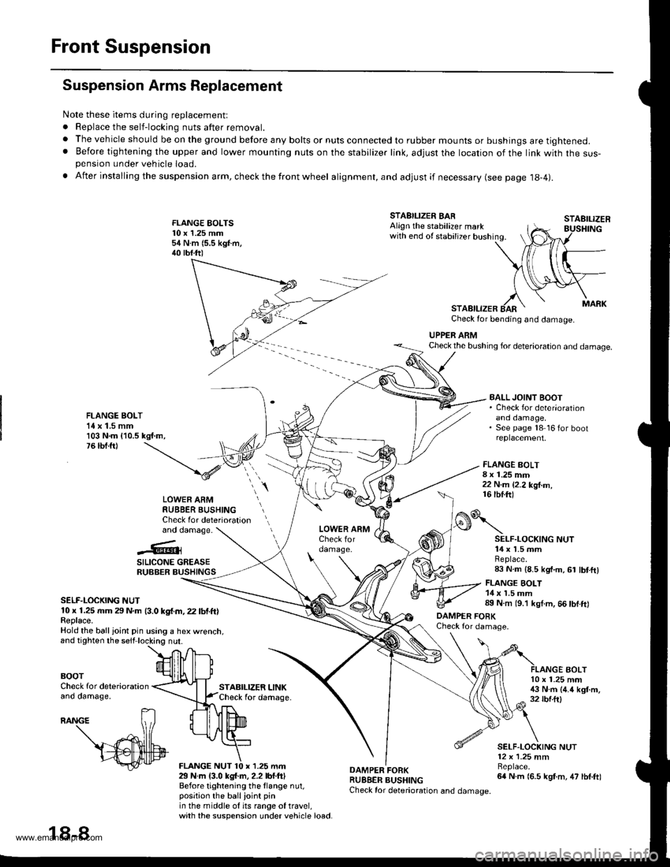
Note these items during replacement:
. Replace the self-locking nuts after removal.
. The vehicle should be on the ground before any bolts or nuts connected to rubber mounts or bushings are tightened.. Before tightening the upper and lower mounting nuts on the stabilizer link, adjusr the location of the link with the sus-pension under vehicle load.
. After insta lling the suspension arm, check the front wheel alignment, and adjust if necessary (see page 18-4|.
FLANGE EOLTS10 x 1.25 mm54 N.m (5.5 kgf.m,40 tbf.ft)
STABILIZER LINKCheck for daftage.
FLANGE BOLT8 x 1.25 mm22 N.m {2.2 kg{.m,16 tbf.ftl
STAEILIZER
AOLT
STABILIZER BARAlign the stabilizer markwith end of stabilizer bushing.
STABILIZERCheck for bending and damage.
UPPER ARMCheck the bushing for deterioration and damage.
FLANGE BOLT1{ x 1.5 mm103 N.m {10.5 kgf.m,76 tbf.ft)
BALL JOINT BOOT. Check for deter'orationano oamage,See page 18 16 for bootreplacement.
LOWER ARMRUBBER BUSHINGCheck for deteriorationand damage.
..'.{l@3
SILICONE GREASERUBBER BUSHINGS
SELF-LOCKING NUT10 x 1.25 rr|m 29 N.m (3.0 kgf.m, 22 lbf.ft)Feplace.Hold the ball ioint pin using a hex wrenct
BOOTCheck for deteriorationano oamage,
29 N.m {3.0 kgl.m, 2.2 lbf.ftlBefore tightening the llange nut,position the ballioint pinin the middle of its range of travel,with the suspension under vehicle load.
DAMPER FORKRUBBER BUSHINGCheck for deterioration and damage.
o\
DAMPER FOBKCheck for damage.
SELF.LOCKING NUT14 x 1.5 mmReplace.83 N.m (8.5 kgt.m, 61 lbt.ftl
FLANGE BOLT14 x 1.5 mm89 N.m (9.'l kgl.m, 66 tbf.ft)
10 x 1.25 mm!$ N.m (4.4 kgt.m,32 rbf.ftl
SELF.LOCKING NUT12 x 1.25 mmBeplace.64 N.m (6.5 kgt.m, 47 lbf.ft)
18-8
www.emanualpro.com
Page 914 of 1395
Front SuspensionFront Damper
Ball Joint Boot Replacement
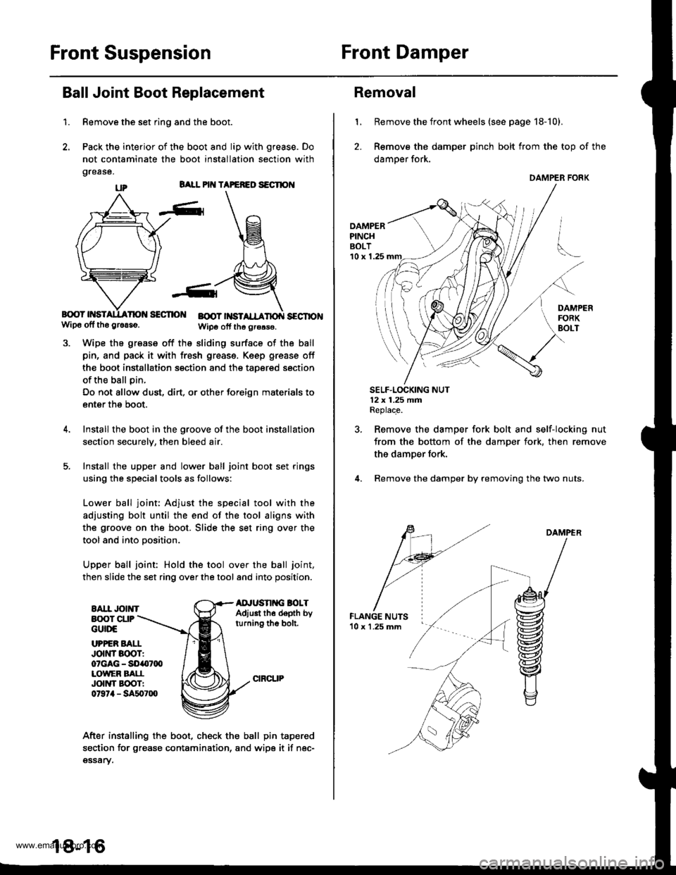
1.
BALL PIT{ TAPEFEO S€CTION
B{rcY HSISECTIO BOOT |NSTSECTIONwip6 off tho gr6aso.Wipo otf th6 grors€.
Wipe the grease off the sliding surface of the ball
pin, and pack it with fresh greass. Keep grease off
the boot installation section and the taoered section
of the ball pin.
Do not allow dust, dirt, or other foreign materials to
enter the boot.
Install the boot in the groove of the boot installation
section securelv, then bleed air.
Install the upper and lower ball joint boot set rings
using the special tools as follows:
Lower ball joint: Adjust the special tool with the
adjusting bolt until the end of the tool aligns with
the groove on the boot. Slide the set ring over the
tool and into oosition.
Upper ball joint: Hold the tool over the ball joint,
then slide the set ring over the tool and into position.
EAII JOINTAD'USN G BOLTAdjust th6 depth byturning the bolt.
Remove the set ring and the boot.
Pack the interior of the boot and lip with grease. Do
not contaminate the boot installation section with
grease.
B(X)T CUPGUttrE
UPPER BAI.IJott'tr Boor:07GAG - SO407q)LOWEF BATIJOIIYI EOOTI0t97il - SA507lXl
After installing the boot, check the ball pin tapered
section for grease contamination, and wipe it if nec-gssary.
18-16
Removal
1, Remove the front wheels (see page 18-10).
2. Remove the damper pinch bolt from the top of the
damper fork.
DAMPERPINCHBOLT'10 x 1.25
SELF.LOCKING NUT12x 1.25 fifiReplace.
Remove the damper fork bolt and self-locking nut
from the bottom of the damper fork, then remove
the damper fork.
Remove the damper by removing the two nuts.
DAMPER
DAMPER FORK
www.emanualpro.com
Page 916 of 1395
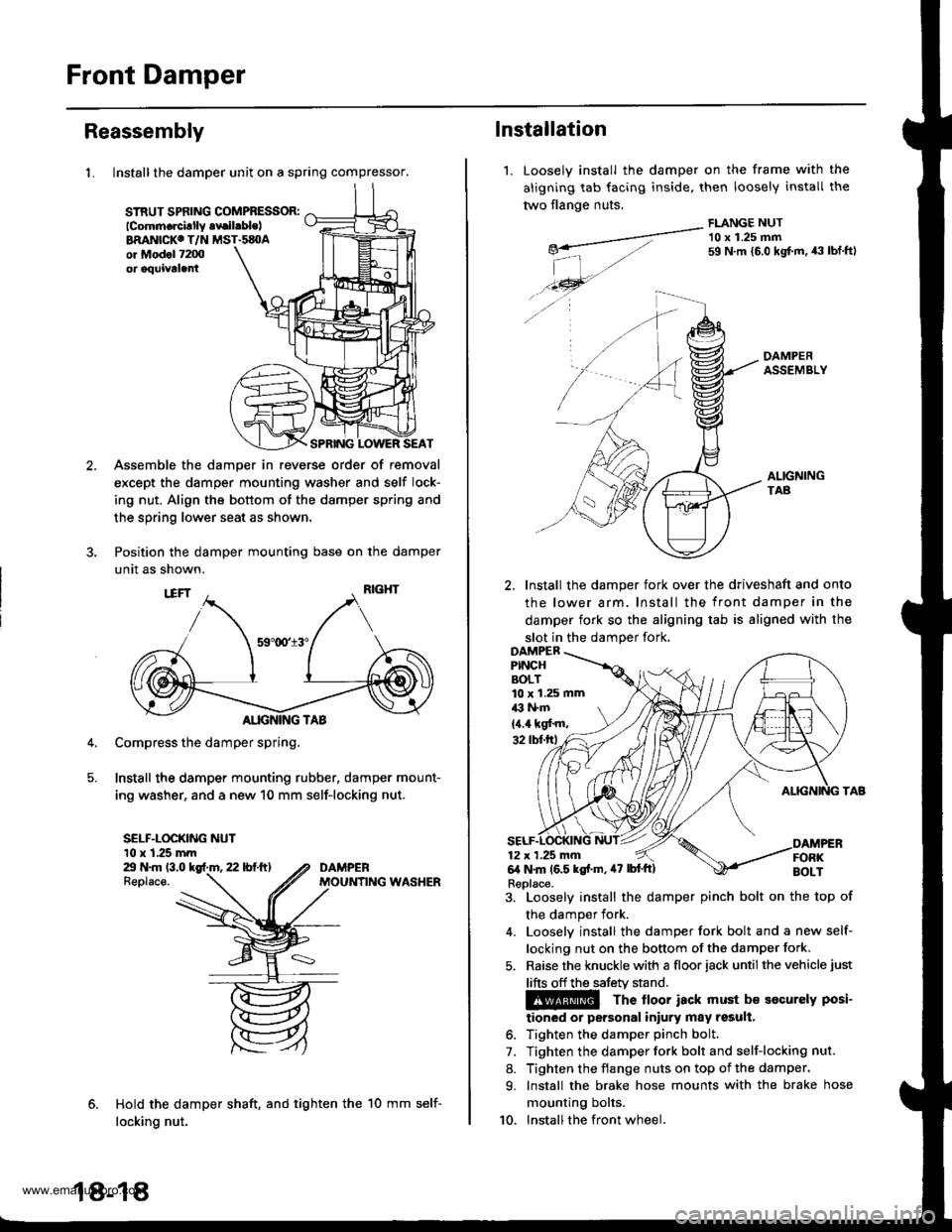
Front Damper
Reassembly
1. Install the damper unit on a spring compressor.
STRUT SPflNG COMPBESSOR:lcomm.rcillly .vrilrble)BRANICKC T/N MST.sEOAor Mod.l 7200or oquivtla
SPRING LOWER SEAT
Assemble the damper in reverse order of removal
except the damper mounting washer and self lock-
ing nut. Align the bottom of the damper spring and
the spring lower seat as shown.
Position the damper mounting base on the damper
unit as shown.
Compress the damper spring,
Install the damper mounting rubber, damper mount-
ing washer, and a new 10 mm self-locking nut.
SELF-LOCKING NUT10 x 1.25 mmZt N.m 13.0 kgf.m, 22 lbf.ft)Replace.
Hold the damper shaft, and tighten the
locking nut.
DAMPERMOUNfING WASHER
18-18
10 mm self-
1.
lnstallation
Loosely install the
aligning tab facing
two flange nuts.
damper on the frame with
inside, then loosely install
FLANGE NUT
the
tne
-__---a-"- 10 x 1.25 mmg*- 59 N.m {5.0 kgt m, 43 tbf.ftl
| -,./.46- --...
./ -4 A-
DAMPERASSEMBLY
ALIGNINGTAB
2, Install the damper fork over the driveshaft and onto
the lower arm. Install the front damper in the
damper fork so the aligning tab is aligned with the
slot in the damDer fork,
3. Loosely install the damper pinch bolt on the top of
the damper fork.
4. Looselv install the damper fork bolt and a new self-
locking nut on the bottom of the damper fork.
5. Raise the knuckle with a floor iack until the vehicle just
lifts off the safetv stand.
The lloor iack must b€ socurely posi-
tioned or personal iniury may result.
6. Tighten the damper pinch bolt.
7. Tighten the damper fork bolt and self-locking nut.
8. Tighten the flange nuts on top of the damper.
9. Install the brake hose mounts with the brake hose
mounting bolts.
10. Installthe front wheel.
10 x 1.25 mmil3 l+m
{4.4 kgf'm,
Replace.
www.emanualpro.com