Heater hose HONDA CR-V 2000 RD1-RD3 / 1.G Workshop Manual
[x] Cancel search | Manufacturer: HONDA, Model Year: 2000, Model line: CR-V, Model: HONDA CR-V 2000 RD1-RD3 / 1.GPages: 1395, PDF Size: 35.62 MB
Page 29 of 1395
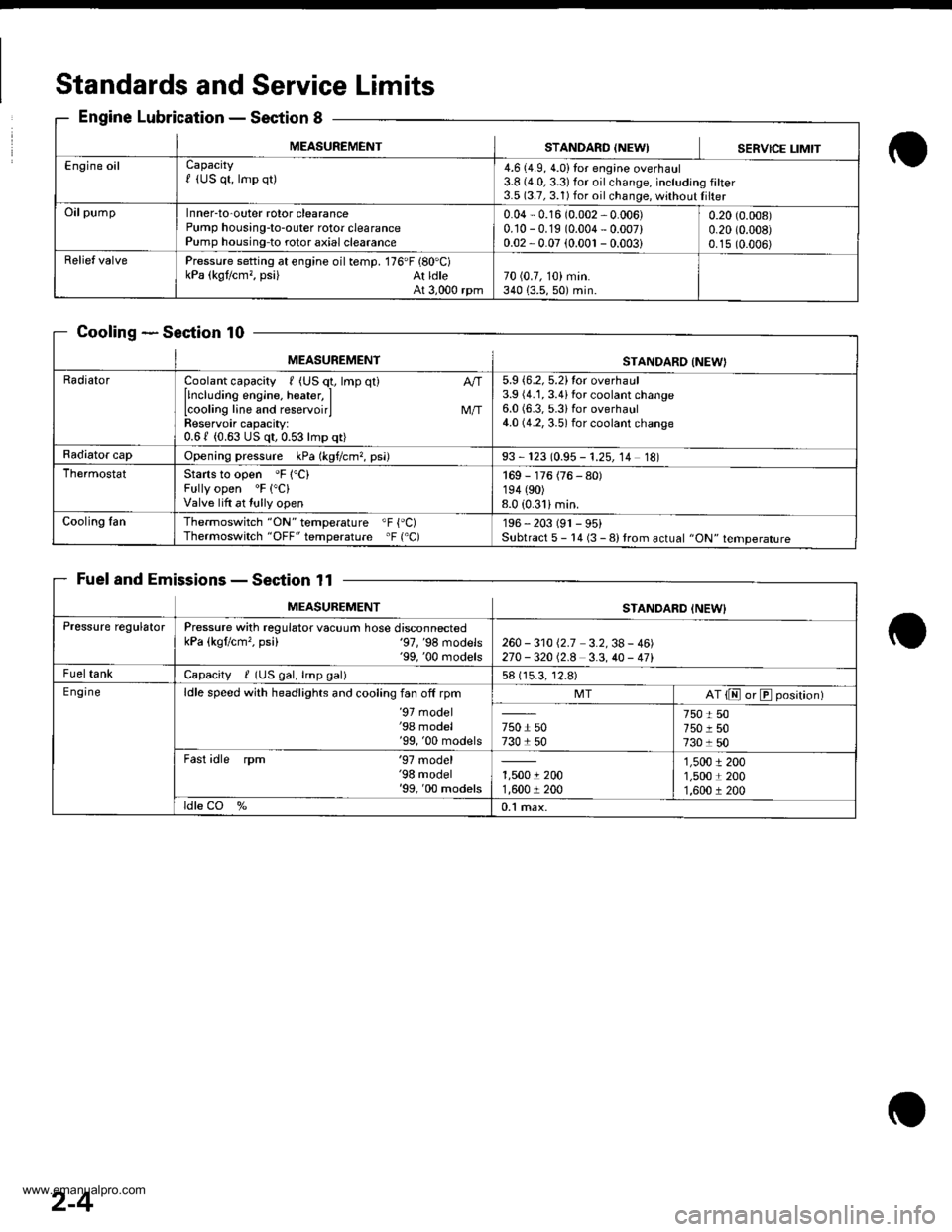
Standards andService Limits
Engine LubricationSection 8
CoolingSection 10
Fuel and EmissionsSection 11
MEASUREMENTSTANDARO {NEWISERVICE LIMIT
Engine oilCapacityf (US qt, lmp qt)4.6 (4.9, 4.0)Ior engine overhaul3.8 {4.0,3.3)for oilchange, including filter3.5 (3.7, 3.1) for oil change, without Iilter
OilpumpInner-to-outer rotor clearancePump housing-to-outer rotor clearancePump housing-to rotor axial clearance
0.04 - 0.16 (0.002 - 0.006)0.10 -0.19 (0.004 - 0.007)0.02 -0.07 (0.001 - 0.003i
0.20 (0.008)
0.20 (0.008)
0.15 (0.006)
Relief valvePressure setting at engine oil temp. 176'F (80'C)kPa (kgt/cm,, psi) At ldleAt 3,000 rpm70 (0.7, 10) min.340 {3.5,50) min.
MEASUREMENTSTANDARO INEW}
RadiatorCoolant capacity , (US q1, lmp qt)
llncluding engine, heater, ILcooling line and reservoirlReservoir capacity:0.61 (0.63 US qt,0.53lmp qt)
M/T
5.9 {6.2, 5.2}tor overhaul3.9 (4.1, 3.4ifor coolant change6.0 (6.3, 5.3ifor overhaul4.0 (4.2, 3.5) for coolant change
Radiator capOpening pressure kPa (kgf/cm?, psi)93 - 123 (0.95 - 1.25, 14 18)
ThermostatStarts to open 'F 1"C)Fully open 'F ("C)
Valve lift at tully open
169 - 176 (76 - 80)194 (90)
8.0 (0.31imin.
Cooling fanThermoswitch "ON" temperature "F {'C)Thermoswitch "OFF" temperature 'F ('C)196 - 203 (91 - 95)Subtract 5 - 14 (3 - 8) trom actual "ON" temperature
MEASUREMENTSTANDARD INEW}
Pressure regulatorPressure with regulator vacuum hose disconnectedkPa (kgflcm'�, psi) '97,'98 models'99, '00 rnodels260 - 31012.7 3.2,38- 46)270 -32012.8 3.3,40 - 471
FueltankCapacity / (US gal, lmp gal)58 (15.3, 12.8)
E ngineldle speed with headlights and cooling fan off rpm'97 model'98 model'99, '00 models
MTAT {E or E position)
750 r 50730 1 50
750 t 50750 r 507301 50
Fast idle rpm '97 model'98 model'99, '00 models1,5001 2001,600 r 200
1,5001 2001,5001 2001,600 r 200
ldle CO %0.1 max.
2-4
www.emanualpro.com
Page 105 of 1395
rd
te
n-
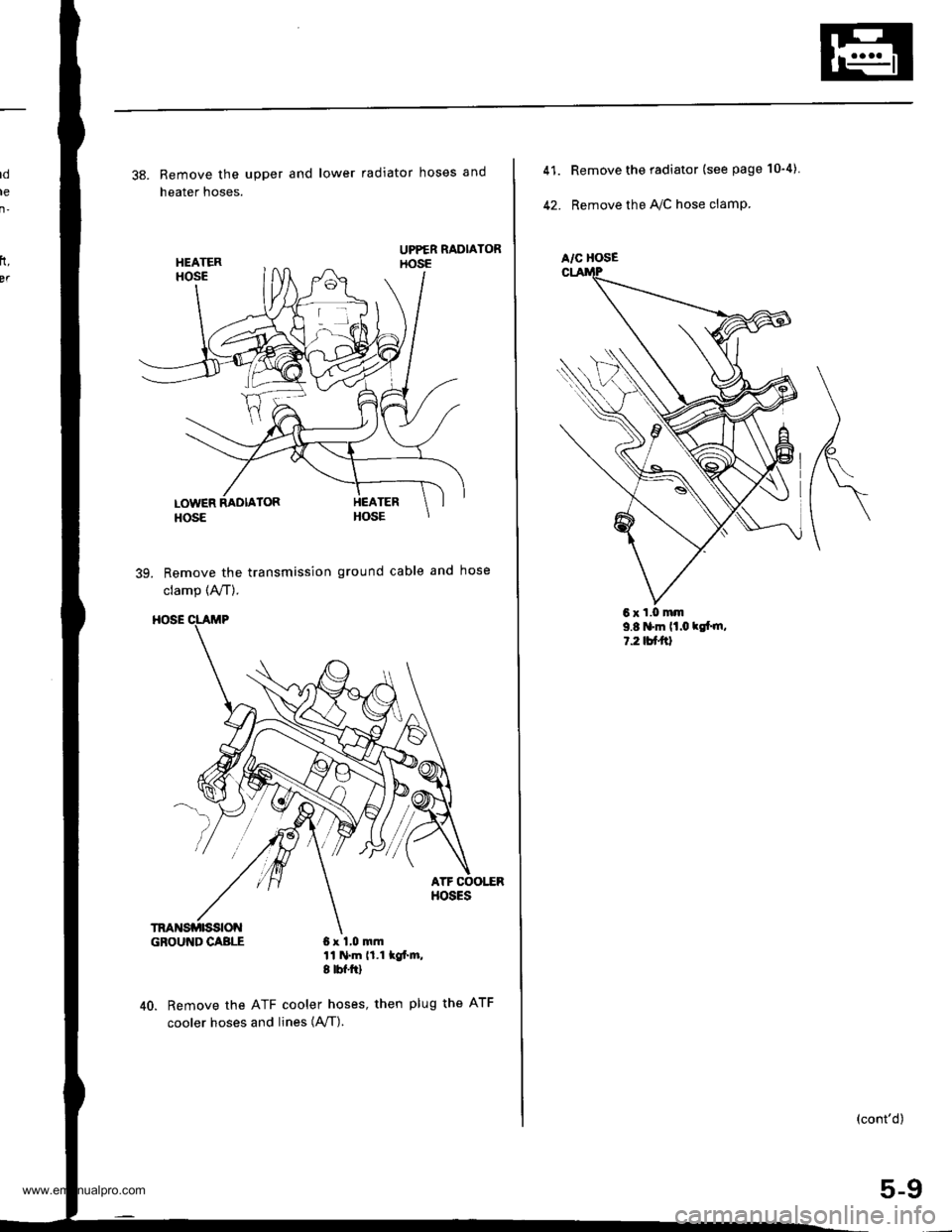
38. Remove the upper and lower radiator hoses and
heater hoses.
39. Remove the transmission ground cable and hose
clamp (A,/T).
GBOUI{DCABLE 6x 1,0 mm11 N.m 11.1 lof'm,I tbf.ftl
40. Remove the ATF cooler hoses, then plug the ATF
cooler hoses and, n"" lAfI).
rt,
BT
6xl,0mm
A/C HOSE
41.
42.
Remove the radiator (see page 10"4).
Remove the IVC hose clamp.
9.8 'm lt.o klt m,l.2tutal
(cont'd)
5-9
www.emanualpro.com
Page 132 of 1395

13. Remove the upper radiator hose, heater hose and
water bypass hose.
WATER BYPASS
UPPEBRADIATORHOSE
17
HEATERHOSE
Remove the engine wire harness connectors and
wire harness clamps from the cylinder head and the
intake manifold.
o Four fuel injector connectors
. Engine coolant temperature (ECT) sensor con-
neclor
. Radiator fan switch connector
. Coolant temperature gauge sendlng unlt connec-
tor
. Throttle position sensor connector
. Manifold absolute pressure {MAP) sensor con-
nector
Primary heated oxygen sensor (primary HO2S)
connector
ldle air control (lAC) valve connector
Distributor connector
Remove the spark plug caps and distributor from the
cylinder head.
Remove the cruise control actuator (see section 4).
Support the engine with a jack, then remove the
upper bracket. Make sure to place a cushion
between the oil pan and the iack (see page 6-10).
a
18. Remove the cylinder head cover.
19. Inspect the timing belt (see page 6-9).
CYLINDER
(cont'd)
6-19
www.emanualpro.com
Page 190 of 1395
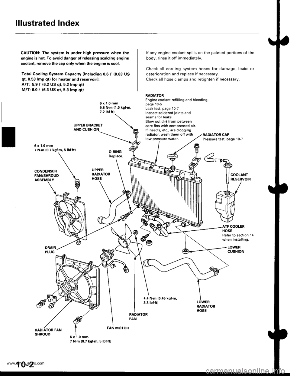
lllustrated Index
CAUTION: The system is under high pressure when the
engine is hot. To avoid danger ol releasing scalding engine
coolant, remove the cap only when the engine is cool.
Total Cooling System Capacity fincluding 0.6 I (0.63 US
qt, 0.53 lmp qt) for heater and reservoirl:
A/T: 5.9 { {6.2 US qt, 5.2 lmp qt)
M/T: 6.0 f (6.3 US $, 5.3 lmp qt)
deterioration and replace if necessar,.
Check all hose clamps and retighten if necessary.
lf any engine coolant spills on the
body, rinse it off immediately.
Check all cooling system hoses
painted portions of the
for damage, leaks or
6x1.0mm9.8 N.m 11.0 kgf.m.1.2 tbl.ftl
RADIATOREngine coolant refilling and bleeding,page 10-5Leak test, page 10 7Inspect soldered joints andseams for leaks.Blow out din from betweencore fins with compressed air.lf insects, etc., are cloggingradiator, wash them off withlow pressure water.RADIATOR CAPPressure test, page 10-7
ATF COOLERHOSEReler to section 14when installing.
LOWERcusHroN
6x1.0mm7 N.m (0.7 kgf.m, 5 lbf ftl
FAN MOTOR
10-2
www.emanualpro.com
Page 318 of 1395
PGM-FI System
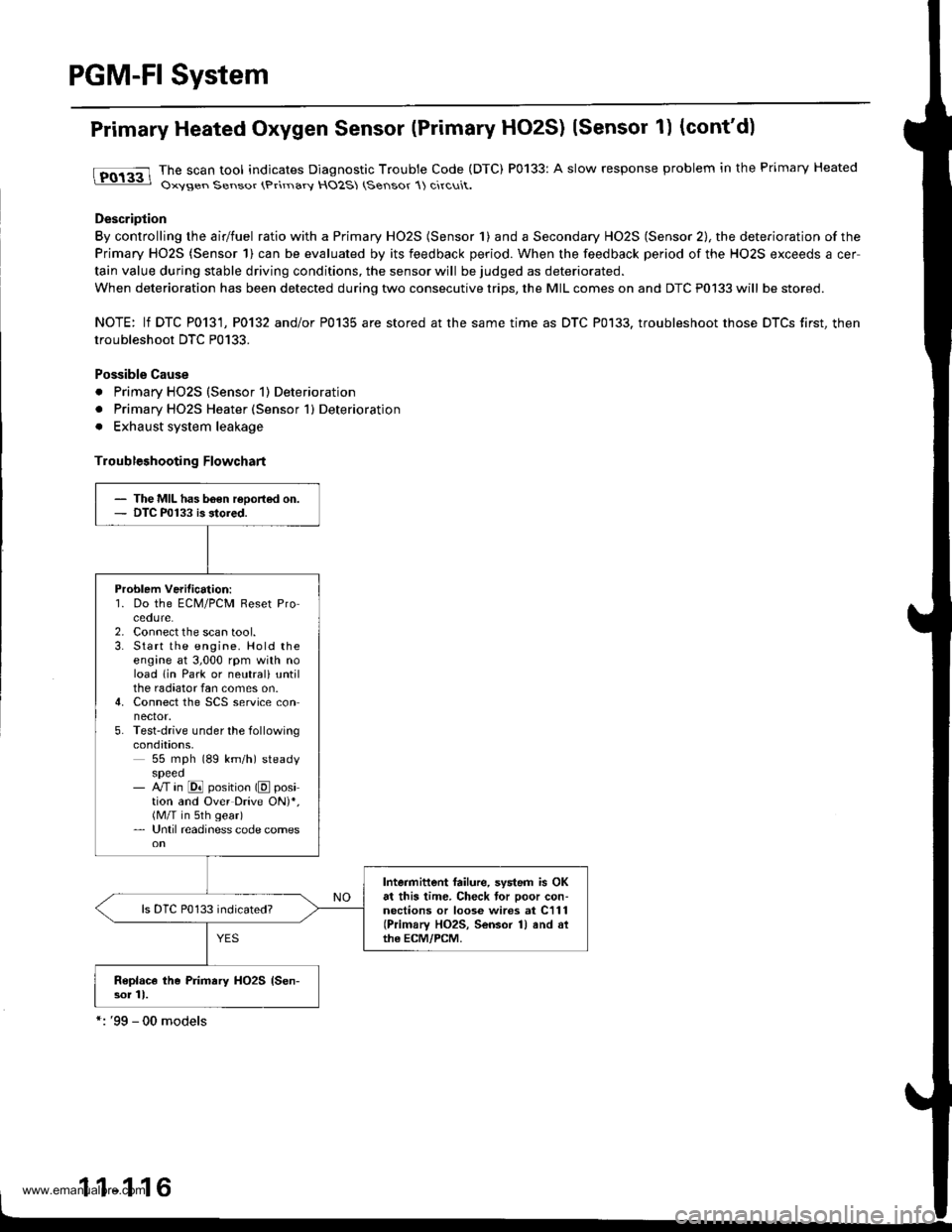
Primary Heated Oxygen Sensor (Primary HO2S) lSensor 1) (cont'd)
tFO133 lhe scan tool indicates Diagnostic Trouble Code (DTC) P0133: A slow response problem in the Primary Heated: Oxysen Sensor (Primarv HO2S (Sensor 1) circuit.
Description
By controlling the airlfuel ratio with a Primary HO2S (Sensor 1) and a Secondary HO2S (Sensor 2), the deterioration of the
Primary HO2S (Sensor 1) can be evaluated by its feedback period. When the feedback period of the HO2S exceeds a cer
tain value during stable driving conditions, the sensor will be judged as deteriorated.
When deterioration has been detected during two consecutive trips, the MIL comes on and DTC P0133 will be stored.
NOTE: lf DTC P0131, P0132 and/or P0135 are stored at the same time as DTC P0133. troubleshoot those DTCS first, then
troubleshoot DTC P0133.
Possible Cause
. Primary HO2S (Sensor 1) Deterioration
. Primary HO2S Heater (Sensor 1) Deterioration
. Exhaust system leakage
Troubleshooting Flowchart
- The MIL has b6€n reoorted on.- DTC P0133 is stored.
Problem Verilication:'1. Do the ECM/PCM Reset Procedure.2. Connect the scan tool.3. Start the engine. Hold theengine at 3,000 rpm with noload lin Park or neutrali untilthe radiator fan comes on.4. Connect the SCS service connector.5. Test-drive under the followingcondations,55 mph (89 km/h) steadyspeed- M in @ position (E position and Over Drive ON)*,(M/T in sth gear)- Until readiness code comes
Intermittent failure, system is OKat this time. Check tor poor con-nections or loose wires at C111(Primary HO2S, Sensor 1) and althe ECM/PCM.
Replace the Primary HO2S {Sen-sor 11.
1 1-1 16
www.emanualpro.com
Page 326 of 1395
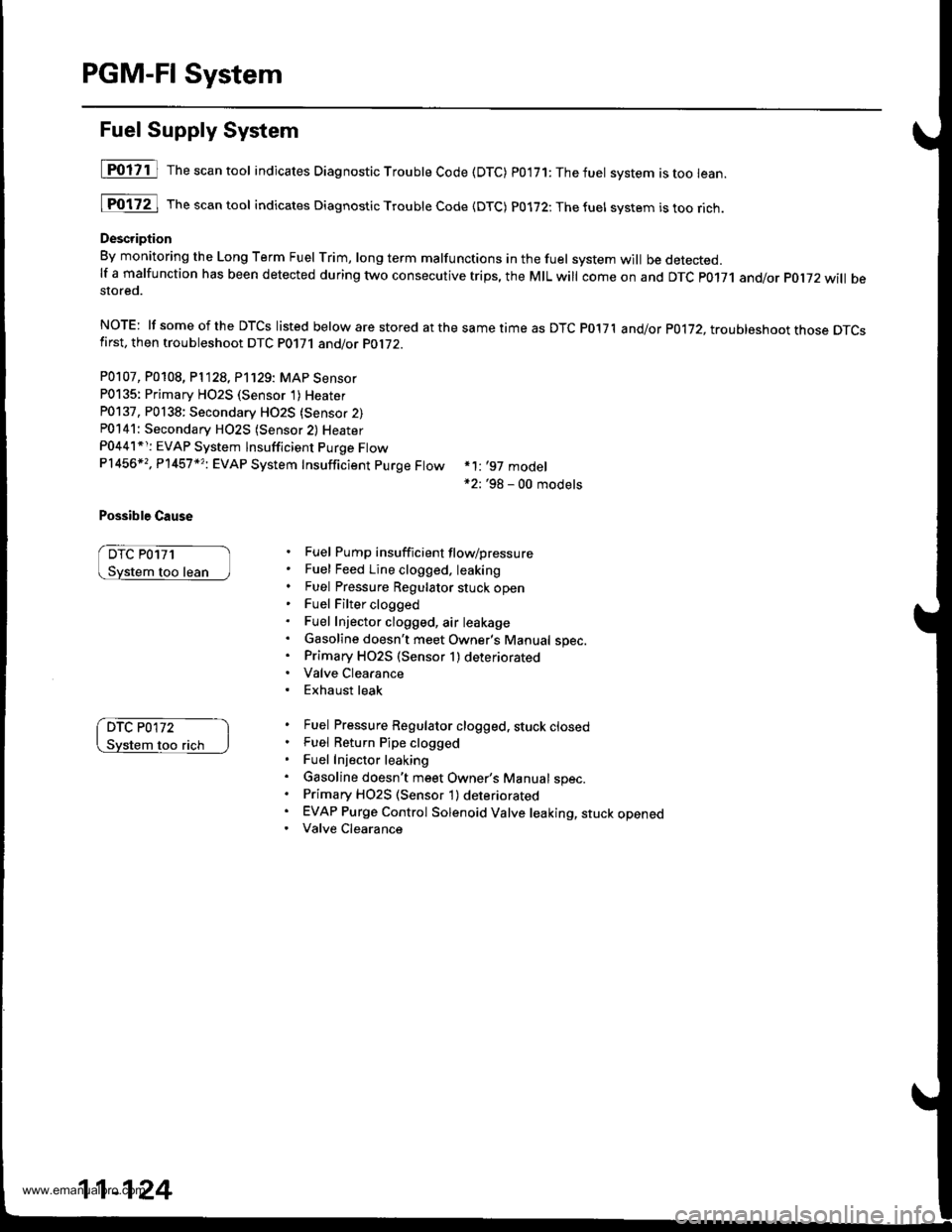
PGM-FI System
Fuel Supply System
[POliil The"""ntool indicates Diagnostic Troubte Code (DTC) p0'171:Thefuet system istoo lean.
[Fo17ZJ rh""""ntool indicates Diagnostic Troubte code {DTc) p0172:Thefuel svstem istoorich.
Description
By monitoring the Long Term Fuel rrim, long term malfunctions in the fuel system will be detected.lf a malfunction has been detected during two consecutive trips, the MIL will come on and DTc p0171 and/or pol72 will bestored.
NOTE: lf someof the DTCS listed below are stored atthesametimeas DTC P017'l and/or p0172, troubleshoot those DTcsfirst, then troubleshoot DTC P0171 and/or PO1i2.
P0107, P0108, P1128, P'1129: MAP Sensor
P0135: Primary HO2S (Sensor 1)Heater
P0137, P0138: Secondary HO2S {Sensor 2)P0141: Secondary H02S (Sensor 2) Heater
P0441*r: EVAP System lnsufficient Purge FtowP1456*,, P'l457 *?i EVAP System Insufficient purge Ftow
Possible Cause
DTC P0171
too lean
*1: '97 model*2: '98 - 00 models
Fuel Pump insufficient flow/pressure
Fuel Feed Line clogged. leaking
Fuel Pressure Regulator stuck openFuel Filter clogged
Fuel Injector clogged, air leakage
Gasoline doesn't meet Owner's Manual spec.Primary HO2S (Sensor 1) deteriorated
Valve Clearance
Exhaust leak
Fuel Pressure Regulator clogged, stuck closedFuel Return Pipe clogged
Fuel Injector leaking
Gasoline doesn't meet Owner's Manual spec.Primary H02S (Sensor 1) deteriorated
EVAP Purge Control Solenoid Valve leaking, stuck openedValve Clearance
DTC P0172
flch
11-124
www.emanualpro.com
Page 402 of 1395
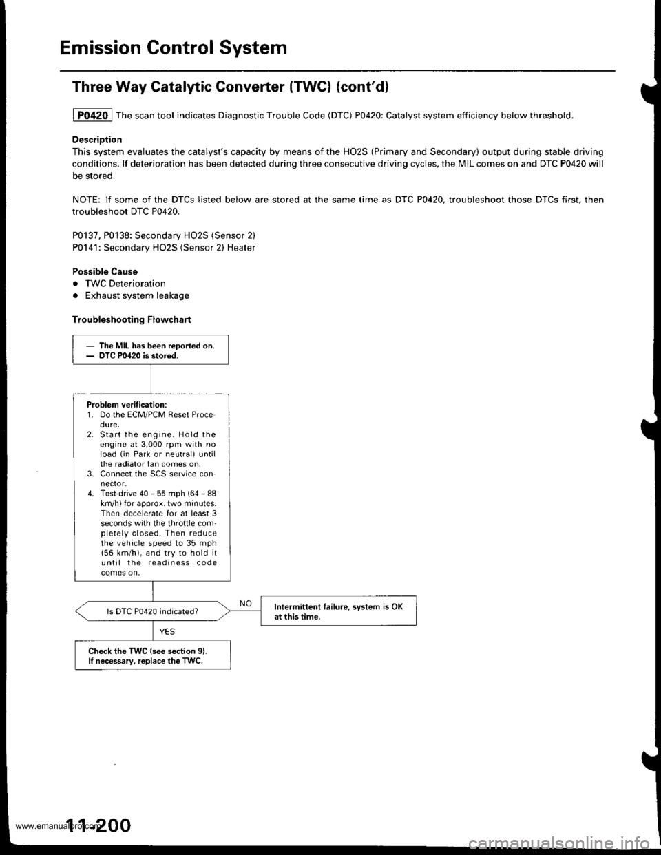
Emission Control System
Three Way Catalytic Converter {TWCI (cont'd}
1P0420 Thescantool indicates Diagnostic Trouble Code (DTC) P0420: Catalyst system efficiency belowthreshold.
DescriDtion
This system evaluates the catalyst's capacity by means of the HO2S (Primary and Secondary) output during stable driving
conditions. lf deterioration has been detected during three consecutive driving cycles, the MIL comes on and DTC P0420 will
be stored.
NOTE: lf some of the DTCS listed below are stored at the same time as DTC P0420, troubleshoot those DTCS first. then
troubleshoot DTC P0420.
P0137, P0138: Secondary HO2S (Sensor 2)
P0141: Secondary HO2S (Sensor 2) Heater
Possible Cause
. IWC Deterioration
. Exhaust system leakage
Troubleshooting Flowchart
- The MIL has been reDoried on.- DTC P0420 is stored.
Problem verification:1. Do the ECM/PCM Reset Procedure,2. Start the engine. Hold theengine at 3,000 rpm with noload (in Park or neutrali untilthe radiator fan comes on.3. Connect the SCS service connector.4. Test-drive 40 - 55 mph (64 - 88km/h) for approx. lwo minutes.Then decelerate for at least 3seconds with the throftle completely closed. Then reducethe vehicle speed to 35 mph
156 km/h), and try to hold ituntil the readiness code
Intermittent tailure. system is OKat this time.ls DTC P0420 indicated?
Check the TWC (see section 9).lI nocessary, replace the TwC.
11-200
www.emanualpro.com
Page 1141 of 1395
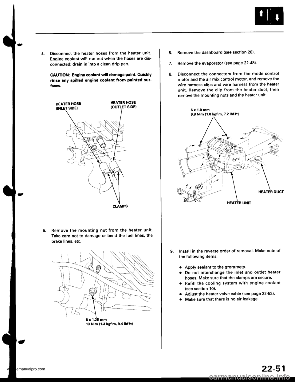
4. Disconnect the heater hoses from the heater unit.
Engine coolant will run out when the hoses are dis-
connected; drain in into a clean drip pan.
CAUTION: Engino coolant will damage p8int. Ouickly
rinse any spill€d engine coolant Itom painted sur-
faces.
HEATER HOSEIOUTLET SIDE)
Remove the mounting nut from the heater unit.
Take care not to damage or bend the fuel lines, the
brake lines. etc.
CLAMPS
13 N.m 11.3 kg{.m,9.4 lbtftl
22-51
7.
ll.
Remove the dashboard (see section 20).
Remove the evaporator (see page 22-48).
Disconnect the connectors from the mode control
motor and the air mix control motor, and remove the
wire harness clips and wire harness from the heater
unit. Remove the clip from the heater duct, then
remove the mounting nuts and the heater unit
6x1.0mm9,8 N.m (1.0 kgt m,7.2lblft)
qInstall in the reverse order of removal. Make note of
the following items.
a
a
a
a
Apply sealant to the grommets.
Do not interchange the inlet and outlet heater
hoses. Make sure that the clamps are secure.
Refill the cooling system with engine coolant
{see section 10).
Adiust the heater valve cable (see page 22-53).
Make sure that there is no air leakage.
HEATER UNIT
www.emanualpro.com