glove box HONDA CR-V 2000 RD1-RD3 / 1.G Workshop Manual
[x] Cancel search | Manufacturer: HONDA, Model Year: 2000, Model line: CR-V, Model: HONDA CR-V 2000 RD1-RD3 / 1.GPages: 1395, PDF Size: 35.62 MB
Page 389 of 1395
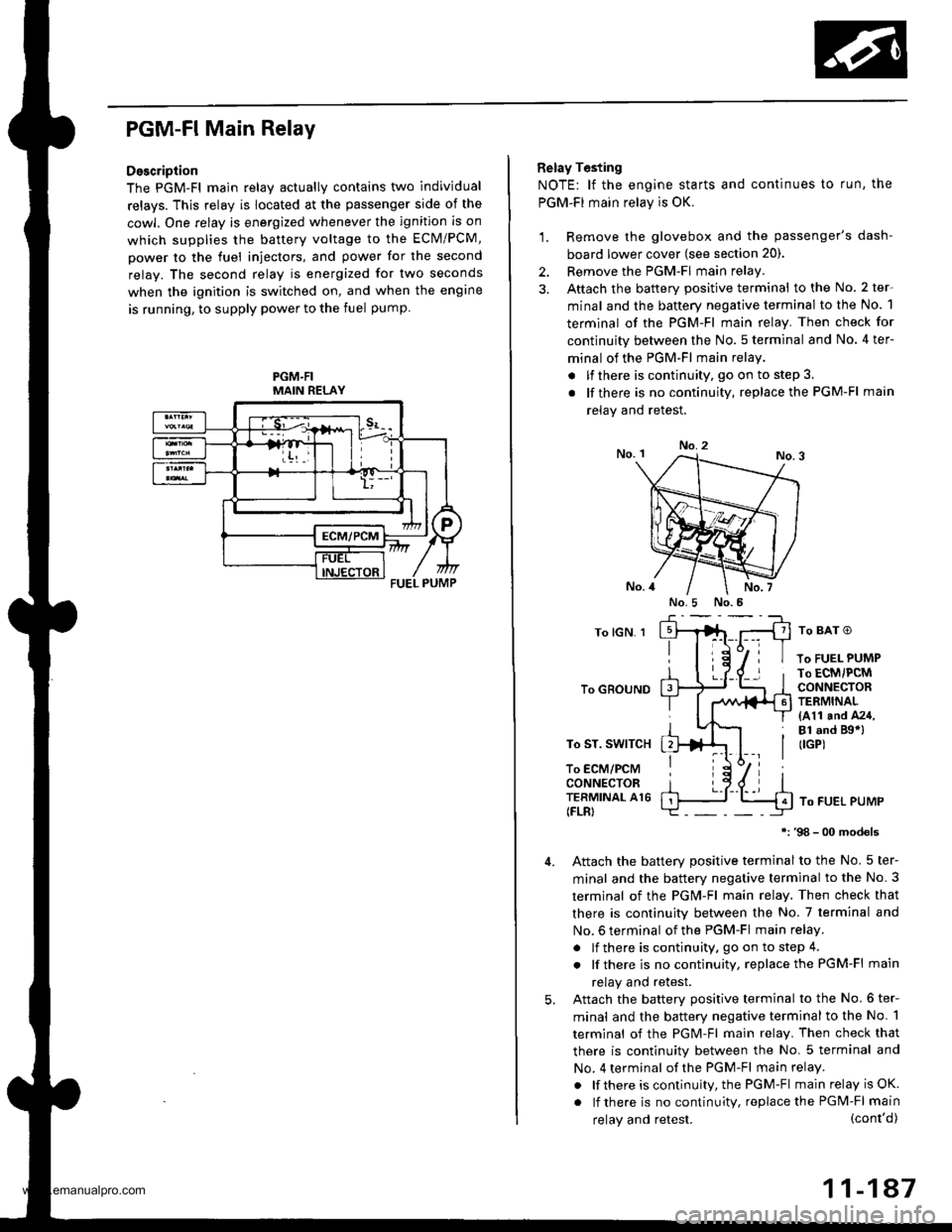
PGM-FI Main Relay
Description
The PGM-Fl main relav actuallv contains two individual
relays. This relay is located at the passenger side of the
cowl. One relay is energized whenever the ignition is on
which supplies the battery voltage to the ECM/PCM,
power to the fuel injectors, and power for the second
relay. The second relay is energized for two seconds
when the ignition is switched on, and when the engine
is running, to supply power to the fuel pump
PGM.FIMAIN RELAY
Belay Testing
NOTE: lf the engine starts and continues to run, the
PGM-FI main relay is OK.
1. Remove the glovebox and the passenger's dash-
board lower cover (see section 20).
2. Remove the PGM-FI main relay
3. Aftach the battery positive terminal to the No. 2 ter-
minal and the battery negative terminal to the No. 1
terminal of the PGM-Fl main relay. Then check for
continuity between the No. 5 terminal and No. 4 ter-
minal of the PGM-FI main relay
. lfthere is continuity, go on to step 3.
. lf there is nocontinuity, replacethe PGM-Fl main
relav and retest.
No.2
To lGN. 1
To GROUND
To ST. SWITCH
To ECM/PCMCONNECTORTERMINAL A16(FLR)
To BAT O
To FUEL PUMPTo ECM/PCMCONNECTORTERMINAL(411 and A24,Bl .nd Bgal(IGP)
To FUEL PUMP
98 - 00 models
Attach the batterv Dositive terminal to the No. 5 ter-
minal and the battery negative terminal to the No. 3
termjnal of the PGM-Fl main relay. Then check that
there is continuity between the No. 7 terminal and
No. 6 terminal of the PGM-FI main relay.
. lf there is continuity, go on to step 4.
. lf there is nocontinuity, replacethe PGM-Fl main
relay and retest.
Attach the batterv oositive terminal to the No.6 ter-
minal and the battery negative terminal to the No. 1
terminal of the PGM-Fl main relay. Then check that
there is continuitv between the No. 5 terminal and
No. 4 terminal of the PGM-Fl main relay.
. lf there is continuity, the PGM-Fl main relay is OK.
. lf there is nocontinuity, replacethe PGM-FI main
5.
(cont'd)
11-147
No.5 No.5
relay and retest.
www.emanualpro.com
Page 846 of 1395

Steering
Special Toofs ............. 17-2
Component Locations
Index ................ ....... 17-3
Troubleshooting
General Troubleshooting ................ 1 7-4
Noise and Vibration ......................... 17-8
Fluid Leaks ............. 17-10
Inspection and Adiustment
Steering Operation .......................... 17-12
Power Assist Check
With Vehicle Parked ....................
Steering Linkage and Gearbox .......
Pump Belt
Rack Guide Adjustment ...................
Fluid Rep|acement ...................,,.,....
Pump Pressure Check .................,,...
*Steering Wheel
Removal ................. 17-18
*Steering Column
Removal/lnstallation ................ ....... 17 -2O
lnspection .............. 17-21
Steering Lock Replacement ............ 17 -22
Power Steering Hoses, Lines
Ffuid Leakage Inspection ................. 17 -23
Repfacement .......... 17-23
Power Steering Pump
Repfacement .......... 17-24
Disassembly ...........17-25
fnspection .............. 17-26
Reassembly ............ 17-28
Power Steering Gearbox
Removal ................. 17-31
Disassembly ........... 17-34
Reassembly ............ 17-40
Ball Joint Boot Replacement .......... 17-50
Installation ............. 17-51
17-12
17-13
17-14
l7-15
17-15
17-16
Disassembly/Reassembly............... 17-18
4'%/b.......... -r'-7--a/
SUPPLEN\EN AL RES\RA(N SYSTES{ (SRS\
This model has an SRS which includes a driver's airbag in the steering wheel hub. a passenger's airbag in the dashboardabove the glove box ('97 - 00 models), and seat belt tensioners in the seat belt retractors ('98 - 00 models). Informationnecessary to safely service the SRS is included in this Service Manual. ltems marked with an asterisk (*) on the contentspage include, or are located near, SBS components. Servicing. disassembling or replacing these items will require specialprecautions and tools, and should only be done by an authorized Honda oearer.
To avoid rendering the SRS inoperative, which could lead to peFonal iniury or death in the event of a sevore trontalcollision. allSRS service work must be performod by an authorized Honda dealer.lmproper service procedurgs, including incorrect removal and installalion of the SRS, could lead to personal iniurycaused by unintontional deployment of th€ airbags {'97 - 00 models), and seat belt tensioners ('98 - 00 modelsl.Do not bump the SRS unit. Otherwise, the system may lail in case ot a collision, or the airbags may deploy when theignition switch is ON (lll.
SRS electrical wiring harnesses are identitied by yellow colof coding. Ralated components are located in the steeringcolumn, front console, dashboard, dashboard lower panel, and in the dashboard above the glove box. Do not use elec-trical test equipment on these cilcuits,
www.emanualpro.com
Page 982 of 1395
Body
Bumpers
Front Bumper Removal and
fnstaflation .........20-72
Rear Bumper Removal and
fnstaflation .........20-74
'Dashboard
lnstrument Panel Removal and
lnstallation .........20-47
Driver's Dashboard Lower Cover and
Knee Bolster Removal and
Installation .........20-48
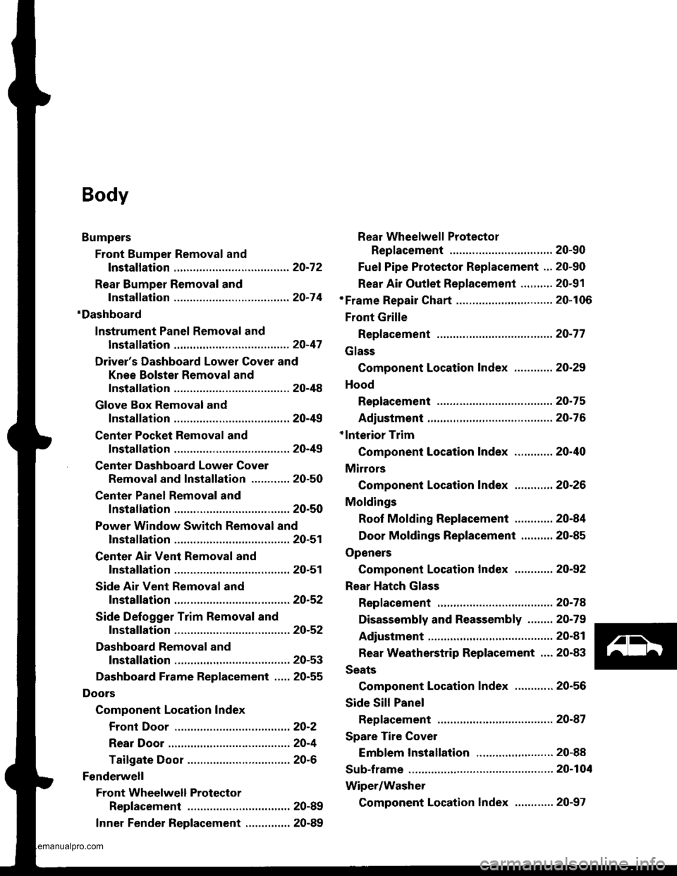
Glove Box Removal and
lnstallation .........20-49
Center Pocket Removal and
lnstallation .........20-49
Center Dashboard Lower Cover
Removal and lnstallation ............ 20-50
Center Panel Removal and
lnstallation .........20-50
Power Window Switch Removal and
lnstallation .........20-51
Center Air Vent Removal and
lnstallation .........20-51
Side Air Vent Removal and
fnstallation .........20-52
Side Defogger Trim Removal and
fnstallation .........20-52
Dashboard Removal and
lnstallation .........20-53
Dashboard Frame Replacement ..... 20-55
Doors
Component Location Index
Front Door ,,...,,,,20-2
Rear Door ...........20-4
Tailgate Door ................................ 20-6
Fenderwell
Front Wheelwell Protector
Replacement .....20-89
Inner Fender Replacement .,.....,.,.... 20-89
Rear Wheelwell Protectol
Replacement .....20-90
Fuel Pipe Protector Replacement ... 20-90
Rear Air Outlet Replacement .......... 20-91
*Frame Repair Chart .............................. 20-106
Front Grille
Repf acement .........20-77
Glass
Component Location Index ............ 20-29
Hood
Replacement ......,,,20-75
Adjustment ............20-76
*lnterior Trim
Component Location Index ............ 20-40
Mirrors
Component Location Index .........,,, 20-26
Moldings
Roof Molding Replacement ............ 20-84
Door Moldings Replacement .......... 20-85
Openers
Component Location Index ............ 20-92
Rear Hatch Glass
Replacement .........20-74
Disassembly and Reassembly ........ 20-79
Adiustment ............20-81
Rear Weatherstrip Replacement .... 20-83
Seats
Component Location Index ............ 20-56
Side Sill Panel
Repfacement .........20-87
Spare Tire Cover
Emblem Installation ........................ 20-88
Sub-frame ..................20-104
Wiper/Washer
Component Location lndex ,,,,,....... 20-97
www.emanualpro.com
Page 1030 of 1395
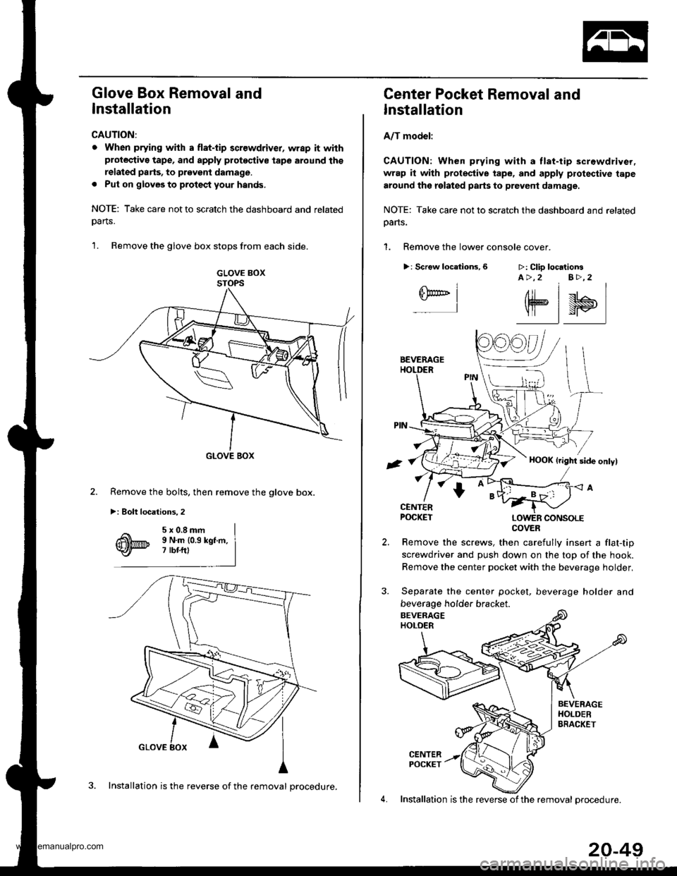
Glove Box Removal and
Installation
CAUTION:
. When prying with a flat-tip 3crewdriver, wrap it withprotective tape, and apply protoqtive tape around ths
related parts, to prgveni damage.
. Put on gloveg to protect your hands.
NOTE: Take care not to scratch the dashboard and related
oarts.
1. Remove the glove box stops from each side.
GLOVE BOXSTOPS
GLOVE BOX
Remove the bolts, then remove the glove box.
>i Bolt locations,2
3. Installation is the reverse of the removal procedure.
20-49
Center Pocket Removal and
Installation
A/T model:
CAUTION: When prying with a tlat-tip screwdriver,
wrap it with protestive tape, and apply protective tape
around the related parts to prevent damage.
NOTE: Take care not to scratch the dashboard and related
oans.
1. Remove the lower console cover.
>: Scrgw locations,6 >: Clip locationsA >,2 B>,2
6F@'' I-l
elsl
Remove the screws, then carefully insert a flat-tip
screwdriver and push down on the top of the hook.
Remove the center pocket with the beverage holder,
Separate the center pocket, beverage holder and
beverage holder bracket.
4. Installation is the reverse of the removal orocedure.
COVER
www.emanualpro.com
Page 1031 of 1395
Dashboard
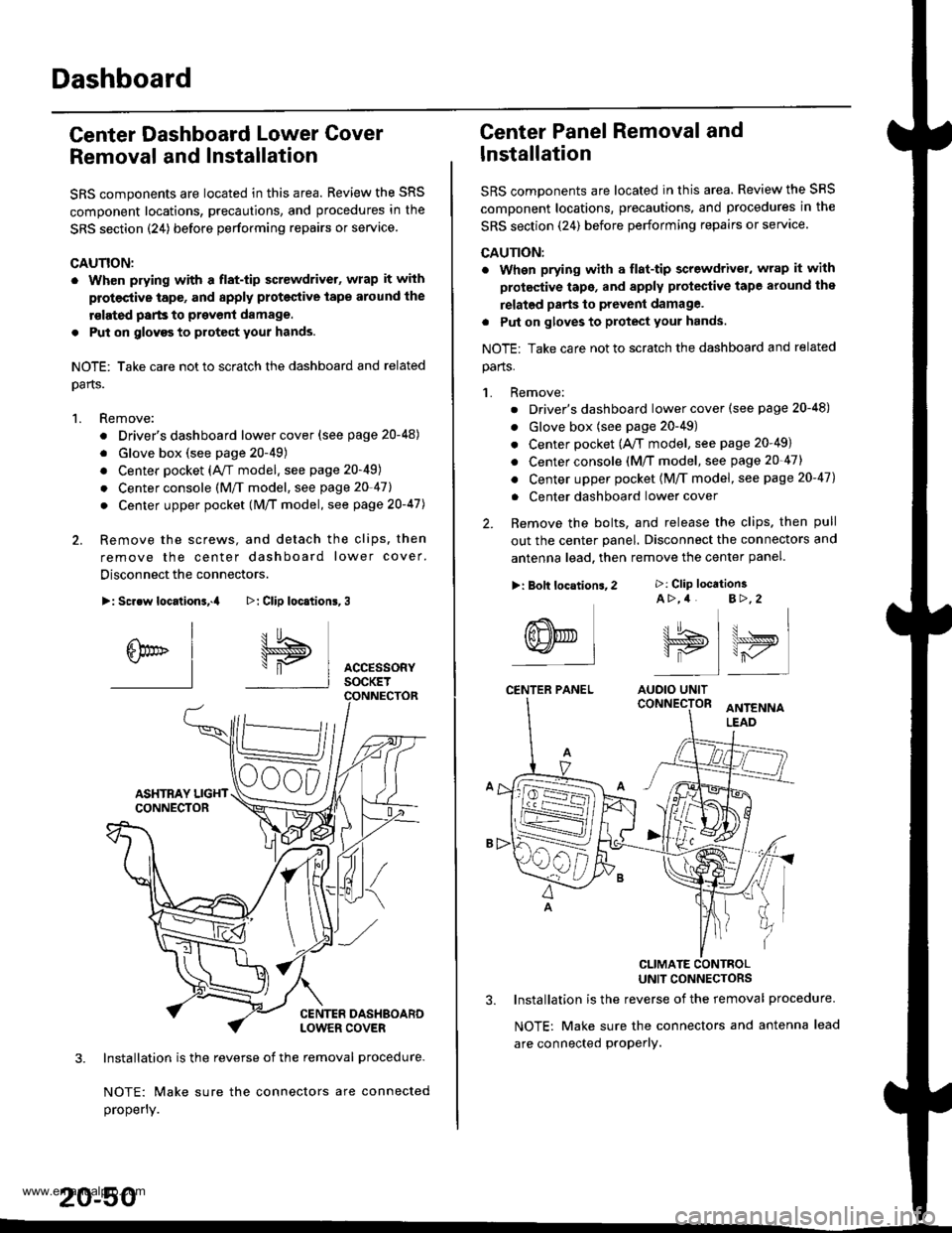
Center Dashboard Lower Gover
Removal and Installation
SRS components are located in this area. Review the SRS
component locations, precautions, and procedures in the
SRS section {24) before performing repairs or service
CAUTION:
. Wh€n prying with a flat-tip screwdrivet, wrap it with
protective tap€, and apply proteclive tape around the
rslated parts to prevenl damage.
. Put on glovgs to protect your hands.
NOTE: Take care not to scratch the dashboard and related
oarts.
1. Remove:
. Driver's dashboard lower cover (see page 20-48)
. Glove box (see page 20-49)
. Center pocket (AVT model. see page 20-49)
. Center console (M/f model, see page 20-41l,
. Center upper pocket (M/T model, see page 2O-47J
2. Remove the screws, and detach the clips. then
remove the center dashboard lower cover.
Disconnect the connectors.
>: Screw locationa,.a
I
6br" I-l
3. Installation is the reverse of the removal procedure-
NOTE: Make sure the connectors are connected
properly.
20-50
>: Clip loc.tion6,3
I5
\"P I AccEssoRyI socKET
Center Panel Removal and
lnstallation
SRS components are located in this area. Review the SRS
comDonent locations, precautions, and procedures in the
SRS section (24) before performing repairs or servace.
CAUTION:
. When prying with a flat-tip screwdriver, wrap it with
protective tape, and apply protective tape around the
relatgd parts to prevent damage.
. Put on gloves to protect your hands.
NOTE: Take care not to scratch the dashboard and related
parts.
1. Remove:
. Driver's dashboard lower cover (see page 20-48)
. Glove box (see page 20-49)
. Center pocket (A,/T model, see page 20-49)
. Center console (M/T model, see page 20-47)
. Center upper pocket {M/T model, see page 20-47)
. Center dashboard lower cover
2. Remove the bolts, and release the clips. then pull
out the center panel. Disconnect the connectors and
antenna lead. then remove the center panel.
CLIMATE CONTBOLUNIT CONNECTORS
3. Installation is the reverse of the removal procedure.
NOTE: Make sure the connectors and antenna lead
are connected proPerly.
>: Clip location3A >,4 B>,2
tt.t !^ t u . I\lJS>,, \>ryI is I r-,/'
AUOIO UNIT
>: Bolt locations,2
(8NED L-l
CENTER PANEL
www.emanualpro.com
Page 1034 of 1395
Dashboard Removal and Installation
SRS components are located in this area. Review the SRS
component locations, precautions, and procedures in the
SRS section {24) before preforming repairs or service.
CAUTION:
. When prying with a flat-tip screwdriver, wrap h withprotective tap€, and apply protective tape around the
related parts to prevgnt damage.
. Put on gloves to prot€ct your hands.
NOTE:
. An assistant is helpful when removing and installing
the dashboard.
. Take care not to scratch the dashboard, bodv and
other related parts.
1.Make sure you have the anti-theft code for the
radio, then write down the frequencies for the
radio's preset buttons.
Disconnect the negative battery cable. and wait at
least three minutes before beginning work.
Removei
a Driver's dashboard lower cover and knee bolster(see page 20-48)
. Glove box (see page 20-49)
. Lower console cover and center pocket (A/T
model, see page 20-49)
. Center console and center upper pocket (M/T
model, see page 20-47)
. Center dashboard lower cover (see page 20-50)
. Power window switch (see page 20-51)
. Driver's side air vent (see page 20-52)
. Driver's side defogger trim (see page 20-52)
Disconnect the driver's airbag connector, and lower
the steering column (see section 17)
NOTE: To prevent damage to the steering column,
wrap it with a shop towel.
2.
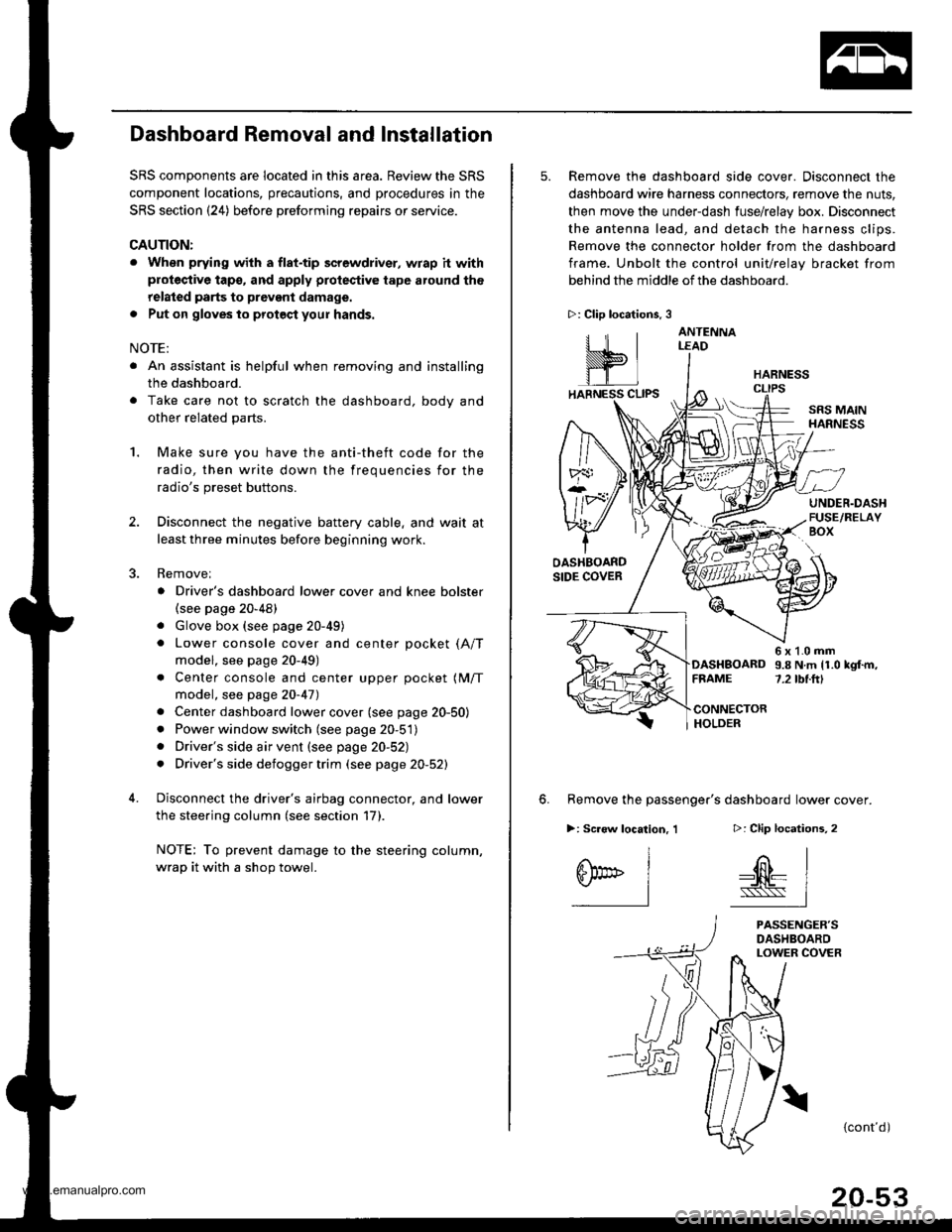
5. Remove the dashboard side cover. Disconnect the
dashboard wire harness connectors, remove the nuts,
then move the under-dash fuse/relay box. Disconnect
the antenna lead, and detach the harness clips.
Remove the connector holder from the dashboard
frame. Unbolt the control unit/relay bracket from
behind the middle of the dashboard.
HARNESS
6. Remove the passenger's dashboard lower cover.
D: Clip locations,
nl
-$t- Issj
I
ANTENNALEAD
>: Clip locations.
rttl
slllll
>: Scr€w location, 1
I
SF:oo I-l
SRS MAINHARNESS
UNDER.DASHFUSE/RELAYBOX
OASHBOARDSIDE COVER
6x1.0mm9.8Nm11.0kgf.m,7.2tbt.ftlDASHBOARDFFAME
CONNECTORHOLDER
PASSENGER'SDASHBOARDLOWER COVER
{cont'd)
www.emanualpro.com
Page 1090 of 1395
a
Heater and Air Conditioning
Heater ...........21
NOTE: Section 21 ("Heater") is included in section 22.
Air Conditioning ......'..'.. '.'22'1
SUPPLEMENTAL RESTRAINT SYSTEM (SRS}
This model has an SRS which includes a driver's airbag in the steering wheel hub, a passenger's airbag in the dashboard
above the glove box ('97,00 models). and seat belt tensioners in the seat belt retractors ('98 - 00 models). Information
necessary to safely service the SRS is included in this Service Manual. ltems marked with an asterisk (*) on the contents
page include. or are located near, SRS components. Servicing, disassembling or replacing these items will require special
precautions and tools, and should only be done by an authorized Honda dealer.
@. To avoid rendering the SRS inoperative, which could lead to personal iniury or death in the event of 8 severe frontal
collision, all SRS service work must be performed by an authotized Honda dealer.
lmproper service procedures, including incorrect removal and installation of the SRS, could lead to personal iniury
caused by unintentional deployment of the airbags ('97 - 00 models), and seat belt tensioners 138 - 00 models).
Do not bump the SRS unit. Otherwise, the system may fail in case of a collision, or the airbags may deploy when the
ignition switch is ON {lll.
SRS eleqtrical wiring harnesses are identified by yellow color coding. Related components are located in the steering
column, front console, dashboard, dashboard lower panel, and in the dashboard above the glove box. Do not use elec-
tricaltest equipment on thes€ cilcuils.
www.emanualpro.com
Page 1138 of 1395
Evaporator
Replacement
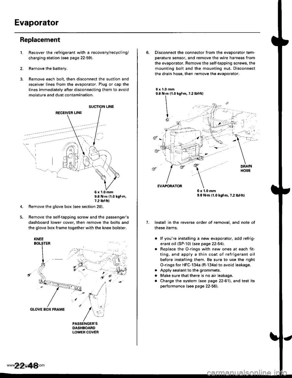
1.Recover the refrigerant with a recovery/recycling/
charging station (see page 22-59).
Remove the battery.
Remove each bolt, then disconnect the suction and
receiver lines from the evaporator. Plug or cap the
lines immediately after disconnecting them to avoid
moisture and dust contamination,
RECEIVER LINE
..
\
6x1.0mm9.8 N'm (1.0 kgf m,7.2 tbl.ttl
Remove the glove box (see section 20).
Remove the self-tapping screw and the passenger's
dashboard lower cover, then remove the bolts and
the glove box frame together with the knee bolster.
GLOVE BOX FRAME
KNEE
22-44
6. Disconnect the connector from the evaoorator tem-
oerature sensor. and remove the wire harness from
the evaporator. Remove the self-tapping screws, the
mounting bolt and the mounting nut. Disconnect
the drain hose, then remove the evaporator.
5xl,0mm9.8 N.m {1.0
II
I
Io
kgf.m, 7.2 lbf.ftl
, -l: "
7.
EVAPORATOR
6x1.0mm9.8 N.m (1.0 kgtm,7.2lbf.ftl
Install in the reverse order of removal, and note of
these items.
. lf you're installing a new evaporator, add refrig-
erant oil (SP.10) (see page 22-541.
Replace the O-rings with new ones at each fit-
ting, and apply a thin coat of refrigerant oil
before installing them. Be su.e to use the right
O-rings for HFC-134a (R-134alto avoid leakage.
Apply sealant to the grommets.
Make sure that there is no air Ieakage.
Charge the system (see page 22-6'll, and test its
performance (see page 22-56]-,
a
a
a
www.emanualpro.com
Page 1140 of 1395
A/C FilterHeater Unit
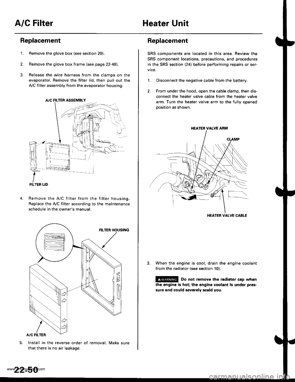
Replacement
1.Remove the glove box (see section 20).
Remove the glove box frame {see page 22-4A).
Release the wire harness from the clamps on the
evaporator. Remove the filter lid, then pull out the
,VC filter assembly from the evaporator housing.
A/C FILTER ASSEMELY
Remove the A/C filter from the filter housing.
Replace the Ay'C filter according to the maintenance
schedule in the owner's manual.
Install in the reverse order of removal. Make sure
that there is no air leakage.
22-50
Replacement
SRS components are located in this area. Review the
SRS component locations, precautions, and procedures
in the SRS section {24) before performing repairs or ser-
1. Disconnect the negative cable from the battery.
2. From under the hood, open the cable clamp, then dis-
connect the heater valve cable from the heater valve
arm. Turn the heater valve arm to the fullv ooened
oosition as shown.
When the engine is cool, drain the engine coolant
from the radiator (see section 10).
@ Do not remove the rldiator cap when
the engine is hot; the engine coolant is under pres-
sure and could sevo.ely scald you.
HEATER VALVE ARM
HEATER VALVE CABLE
www.emanualpro.com
Page 1196 of 1395
![HONDA CR-V 2000 RD1-RD3 / 1.G Workshop Manual
Connector ldentification and Wire Harness Routing
Hoat6r Sub-harness
Connector or
Tgrminal
Numbsr ot
CavitiesLocalionConnects toNotes
c73�]
c731
c732
c733
c734
c735
c736
c737
c738
c739
c7 40
c7 40
5 HONDA CR-V 2000 RD1-RD3 / 1.G Workshop Manual
Connector ldentification and Wire Harness Routing
Hoat6r Sub-harness
Connector or
Tgrminal
Numbsr ot
CavitiesLocalionConnects toNotes
c73�]
c731
c732
c733
c734
c735
c736
c737
c738
c739
c7 40
c7 40
5](/img/13/5778/w960_5778-1195.png)
Connector ldentification and Wire Harness Routing
Hoat6r Sub-harness
Connector or
Tgrminal
Numbsr ot
CavitiesLocalionConnects toNotes
c73'�]
c731
c732
c733
c734
c735
c736
c737
c738
c739
c7 40
c7 40
5
7
7
24
1
Under middle of dash
Under middle of dash
Behind middle of dash
Behind middle of dash
Behind glove box
Behind glove box
Behind glove box
Behind glove box
Behind glove box
Behind glove box
Behind middle of dash
Behind middle of dash
Main wire harness {C436)
Main wire harness (C436)
Mode control motor
Dashboard wire harness (C522)
Air mix control motor
Evaporator temperature sensor
Blower motor high relay
Blower motor
Power transistor
Recirculation control motor
Dashboard wire harness (C523)
Dashboard wire harness (C523)
'97 model'98 - 00
modsls
'97 model'98 - 00
mooels
Combination Switch Sub-harness
Conneqtor ol
Terminal
Number of
CavitiesLocationConnests toNotos
c751
c753
c754
c755
c756
c757
c758
c760
c760
6
7
12
10
2
7
6
8
5
Above under-dash fuse/relay box
Above under-dash fuse/relay box
Under left side of dash
Under left side of dash
Behind steering column
Behind steering column
Behind steering column
Behind steering column
Behind steering column
Behind steering column
Under left side of dash
Under left side of dash
Under-dash fuse/relay box (C914)
Under-dash fuse/relay box {C915)
Main wire harness (C413)
Main wire harness (C413)
Shift lock solenoid
Parking pin switch
Combination light switch
Combination light switch
Wiper/washer switch
Wiper/washer switch
Main wire harness (C442)
Main wire harness (C442)
'97 - 98
mod6ls'99 - 00
models
'97 - 98
models'99 - 00
models
23-36
,
www.emanualpro.com