high beam HONDA CR-V 2000 RD1-RD3 / 1.G Workshop Manual
[x] Cancel search | Manufacturer: HONDA, Model Year: 2000, Model line: CR-V, Model: HONDA CR-V 2000 RD1-RD3 / 1.GPages: 1395, PDF Size: 35.62 MB
Page 76 of 1395
Charging System
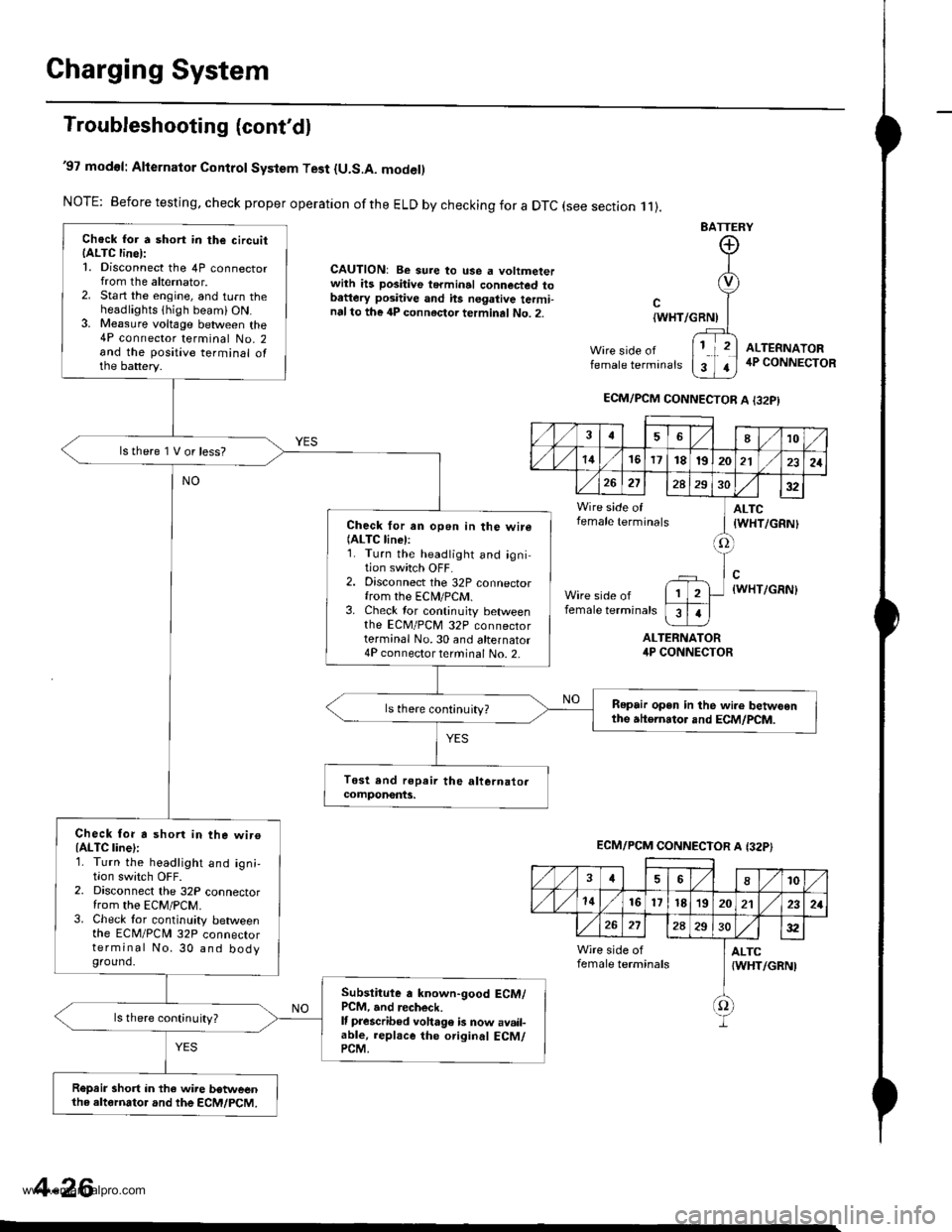
Troubleshooting (cont'dl
'97 modol: Alternator Control System Test {U.S.A. model)
NOTE: Before testing, check proper operation ofthe ELD by checking for a DTC (see section .11).
CAUTION: Be sure to use a voltmeterwith ils positive terminal connected tobattery positive and hs negative termi-nalto the 4P connector terminal No. 2.
BATTERY
Wire side offemale terminals
{WHT/GRNI
ALTERNATORirP CONNECTOR
ALTEFNATOR4P CONNECTOR
Chock for a short in the circuitIALTC line):1. Disconnect the 4P connectorfrom the alternator.2. Start the engine, and turn theheadlights thigh beami ON.3. Me8sure voltage between the4P connector terminal No. 2and the positive terminal ofthe battery.
lstherelVorless?
Check for an open in the wire(ALTC linel:1. Turn the headlight and igni-tion switch OFF.2. Disconnect the 32P connectorfrom the ECN4/PCM.3. Check tor continuity betweenthe EcM/PcM 32P connectorterminal No.30 and alternator4P connector terminal No. 2-
Repair open in the wi.e betwoenthe atternator and ECM/PCM.ls there continuity?
Check for a shorl in the wiroIALTC line):1. Turn the headlight and ign;,I|on swrtcn UFF2. Disconnect the 32P connectorfrom the EcM/PcM.3. Check tor continuity betweenthe ECM/PCN4 32P connectorterminal No. 30 and bodyground.
Subslitute a known-good ECM/PCM, and recheck.It prescribed voha96 b now avail-able, replace the original ECM/PCM.
ls there continuity?
R€prir short in the wire betweenthe altornator and the ECM/PCM.
ECM/PCM CONNECTOR A I32PI
,/1./1810
./ l./t4161718t9202121
26272A293032
Wire side of ] ALTCfemale terminals I tWHT/cRNl
tlWHT/GRN)
female terminals
I
1
ECM/PCM CONNECTOR A {32P}
,/ ,/46810
,/1,/1416l7t8'1920212321
272A2S30:t2
Wire side of I ALTCfemale terminals {WHT/GRNI
f)
4-26
www.emanualpro.com
Page 77 of 1395
R'oR
l
u
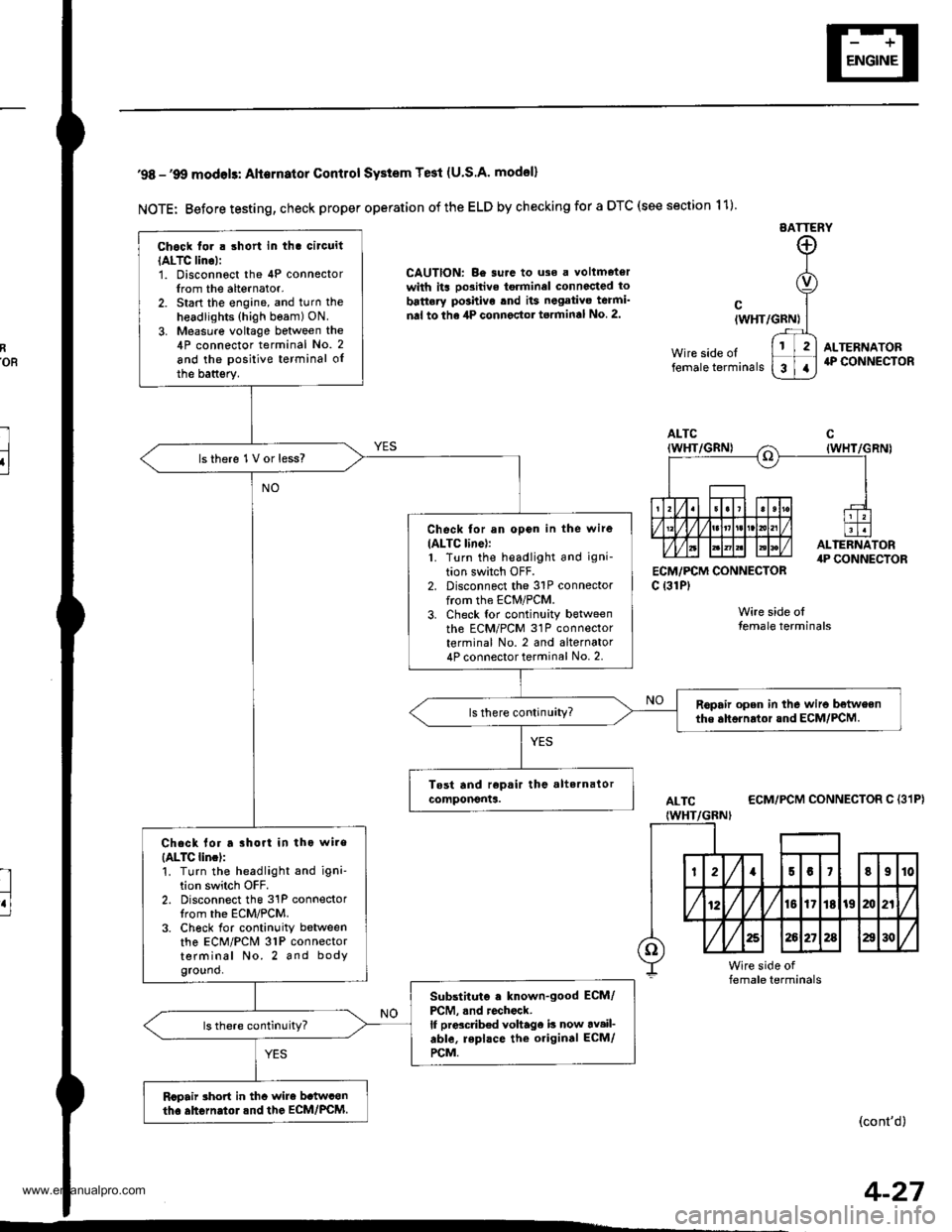
'98 -'9O modols: Alternator Contlol SYstem Te3t (U.S.A' model)
NOTE: Before testing, check proper operation of the ELD by checking for a DTC (see section 11)
EATTERY
CAUTION: Be surc to uso a voltmetorwith its oo3itive torminel connccted to
battery po3hivo tnd its negativo teami'
nal to the 4P connector torminal No 2.
ECM,/PCM CONNECTORc {31P)
Wire side olfemale terminals
cIWHT/GRN)
Wire side oltemale terminals
ALTERNATOR4P CONNECTOR
ALTC
IWHT/GBNI
ECM/PCM CONNECTOR C {31P}
(cont'd)
Chock tor . short in tha circuit
IALTC lino):1. Disconnoct the 4P connectorIrom the alternator.2. Start the engine, and turn the
headlights (high beam) ON.
3. Measure voltage between the4P connector terminal No. 2
and the positive terminal oIthe battsry.
lsthere 1V or less?
Check for an opon in the wire
IALTC line):1. Turn the headlight and igni-
tion switch OFF.2. Disconnect the 31P connectorfrom the ECM/PCM.3. Check tor continuity betweenth6 ECM/PCM 31P connectorterminal No. 2 and alternator4P connector terminal No. 2.
Ropair open in the wiro betweenthe ahornrtor and ECM/PCM.
Chack lor a rhort in tho wire
{ALTC lincl:'!. Turn the headlight and igni'tion switch OFF.2. Disconnect the 31P connectorIrom the ECM/PCM.3. Ch6ck for continuity betweenthe ECM/PCM 31P connectorterminal No. 2 and bodyground.
Substituto . known-good ECM/
PCM, .nd rochock.lf prdcdb€d voltage b now av.il-able, repl.ce the original ECM/
rcM.
Rcpair rhort in thc wire b.twconth. ahGrn.tol.nd the EcM/PcM.
4-27
www.emanualpro.com
Page 1204 of 1395

Power Distribution
Fuse
1
3
5
6
7
I
9
10
11
12
13
14
"^
RED/B LU
RED/GRN
WHT/BLK
RED/VVHT
YEUBLK
RED
GRN/BLK
BLU/BLK
YEVBLK
YEUGRN
RED
BLK/YE L
BLK/VVHT
17
7.5 A
7.5 A
BLVBLU
BLKA/EL
18
19
20
22
7.54
7.54
l0 A
10 A
YEUBLK
YEVRED
BLKAr'YHT
RED /VHT
RED/YE L
Fuse-to-Component(sl Index (numerical sequencel (cont'dl
Under-dash Fuse/Relay Box:
Capacity
10 A
10 A
10 A
10 A
20A
204
15A
204
204
7.5 A'15 A
7.5 A
7.5 A
Wire ColorCircuit{s) Protected
Not used
Not used
Rear window washer motor (via switch)
Rear window wiper control unit ('97 model)
Rear window wiper motor
Daytime running rights resister {Canada)
Right headlight {High beam}
Daytime running rights resister (Canada)
High beam indjcator light
Left headlight (High beam)
Rear accessory socket (via relay)
Left rear power window motor (via switch)
Right rear power window motor (via switch)
Distributor (ignition control module)
Front passenger's power window motor (via switch)
Driver's power window motor {via switch)
Power window master switch (power window control unit)
Turn signal/hazard relay (via switch)
PGM-FI main relay
SRS unit (VA)
Cruise control unit (via switch)
Cruise main switch indicator light
Alternator
Charging system light
ELD unit (USA)
EVAP bypass solenoid valve ('98 - 00 models)
EVAP control canister vent shut valve ('98 - 00 models)
EVAP purge control solenoid valve
Primary HO2S
Secondary H02S
VSS
ABS control unit
Option connector (lG2)
Ay'C compressor clutch relay
Blower motor high relay
Blower motor relay
Condenser fan relay
Heater control panel
Left power mirror actuators (via switch)
Mode control motor
Radiator fan relay
Recirculation control motor
Right power mirror actuators (via switch)
Daytime running lights control unit (Canada)
Back-up lights
Reverse relay (A"/T)
Daytime running lights control unit (Canada)
Right headlight (Low beam)
Left headlight (Low beam)
23-44
www.emanualpro.com
Page 1217 of 1395
l-
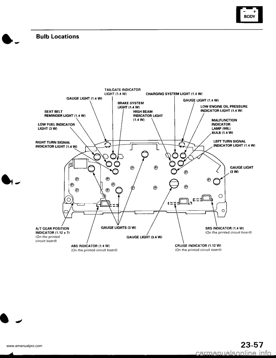
Bulb Locations
TAILGATE INDICATORLIGHT (,I.4 W) CHARGING SYSTEM LIGHT (1.4 WI
GAUGE LIGHT {1.4 WIGAUGE LIGHT I1,4 WIBRAKE SYSTEMLTGHT 11.4 WlLOW ENGINE OIL PRESSUREINDICATOR LIGHT {1./r W}SEAT BELTREMINDER LIGHT {1.' W'HIGH BEAMINDICATOR LIGHT
LOW FUEL INOICATOBLIGHT 13 WI
MALFUNCTIONINOICATORLAMP {MIL)BULB I1.4 WI
{1.4 Wl
RIGHT TURN SIGNALINDICATOR LIGHT I1.' WI
GAUGE LIGHTS 13 WI
LEFT TURN SIGNALINDICATOR LIGHT {1,4 W}
GAUGE LIGHT
t3 wl
SRS INDICATOR ('1./t W)(On the printed circuit board)
1,.
A/T GEAR POSITIONINDICATOR {1.12 x 7}(On the printed
circuit board)GAUGE LIGHT {3.' W}
ABS INDICATOR (1,4 W)
lOn the printed circuit board)cRutsE tNDtcAToR 11.r2 w)(On the printed circuit board)
f-= F -
J
23-57
www.emanualpro.com
Page 1235 of 1395
Lighting System
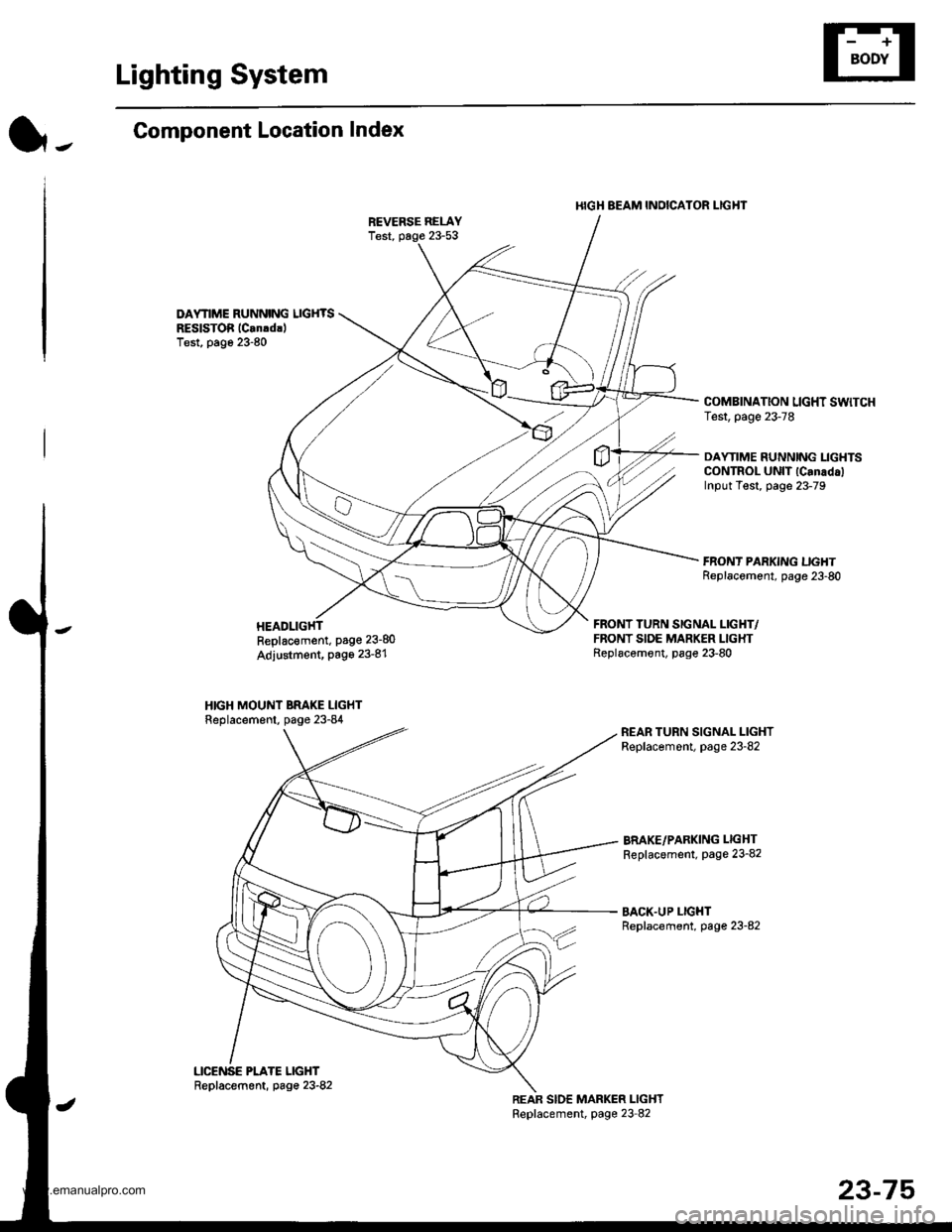
l-.Component Location Index
DAYNME RUNNING LIGHTSREslsToi lCan!drlTest, page 23-80
I{IGH BEAM INOICATOR I-IGHT
COMBINATION LIGHT SWTCHTest, page 23-78
DAYTIME RUNNING LIGHTSCONTROL UNIT lCanadalInput Test, page 23-79
Replac€ment, Page 23-80
Adjustment, Page 23-81
HIGH MOUNT BRAKE LIGHTReplacement, page 23-84
FRONT TURN SIGNAL LIGHT/FRONT SIDE MARKER LIGHTReplacemont, page 23-80
BRAKE/PARKING LIGHT
Replacement, page 23-82
BACK.UP LIGHTReplacement, page 23-82
23-75
www.emanualpro.com
Page 1237 of 1395
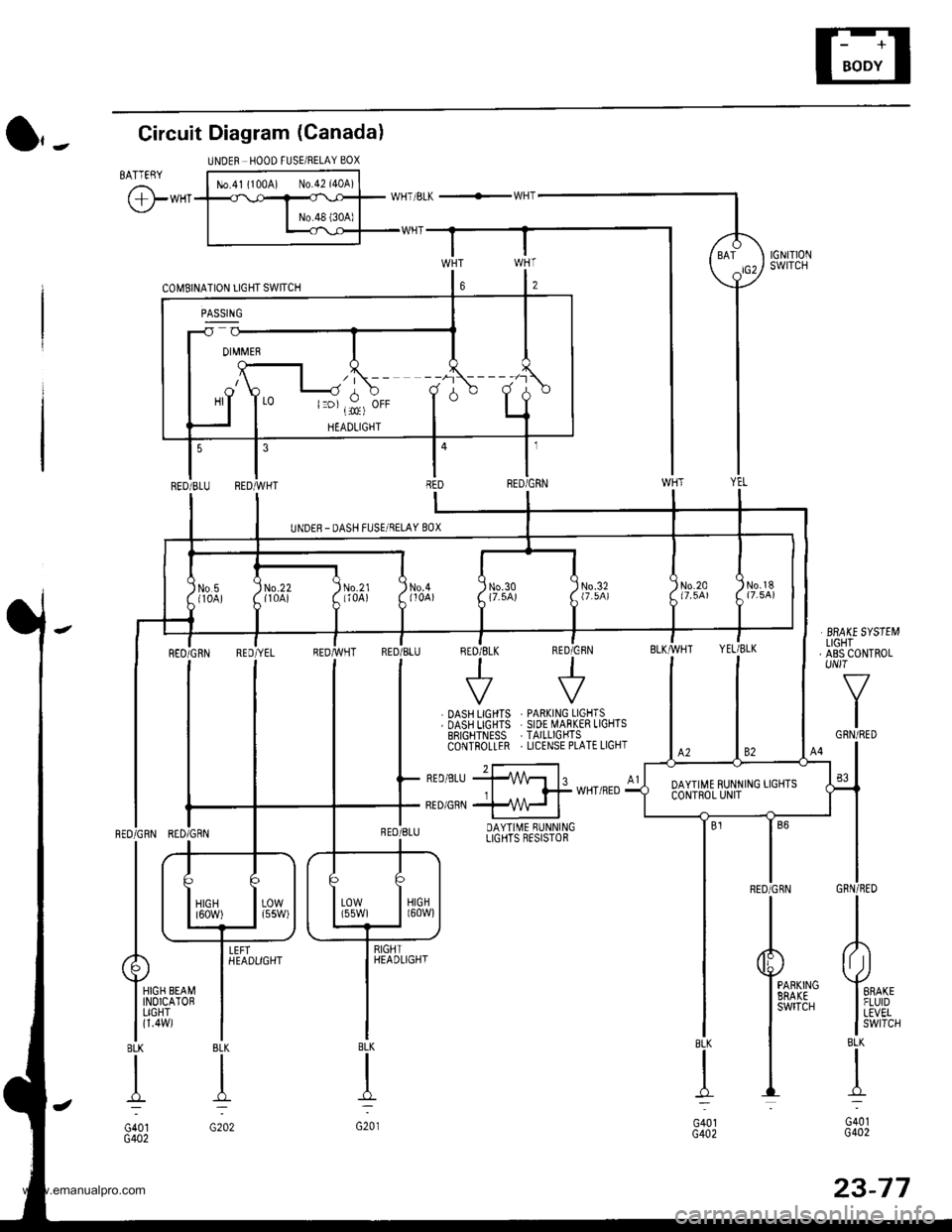
UNDER HOOD FUSEiRELAY 80X
WHT/BLK +WHT
c0t\48rNATroN UGHT SWITCH
4
RED
HIGH BEAMINOICATORLIGHT
l=o) , :., oFF
O,-Circuit Diagram (Canada)
BATTEBY
@*"
UNDER- DASH FUSE/RELAY 8OX
BBAXE SYSTEMLIGHTABS CONTROLUNIT
IIGRN/RED
. DASH LIGHTS ' PARKING LIGHTS, DASH LIGHTS ' SIDE MAHKER LIGHTSERIGHTNESS .TAILLIGHTSCONTHOLLER . LICENSE PLAT€ LIGHT
8LK
d--
G401G402
8LK
-L-::
G40lG402
BLK
I
G20
BLK
I
G202
NEO/CRN
I
T,8LK
I
G401c402
23-77
www.emanualpro.com
Page 1239 of 1395
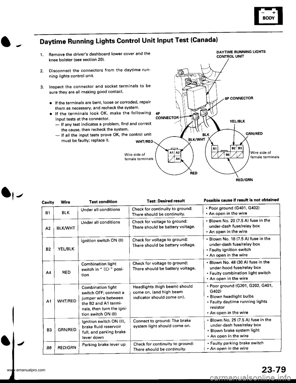
Daytime Running Lights Control Unit Input Test (Canadal
1.Remove the driver's dashboard lower cover and the
knee bolstet (see section 20).
Disconnect the connectors from the daytime run-
ning lights control unit.
Inspect the connector and socket terminals to be
sure they are all making good contact.
lf the terminals are bent, loose or corroded, repair
them as necessary, and recheck the system.
lf the terminals look OK, make the tollowing
inout tests at the connector'
- lf anv test indicates a problem, find and correct
the cause, then recheck the system.
- lf all the input tests prove OK, the control unrt
IPCONNECTOR
must be faulty; replace it.
T€st condition
DAYTIME RUNNING LIGHTS
CONTBOL UNIT
Tost: Desired result
8P CONNECTOR
YEL/BLK
GRN/RED
Possible cause ii r$uh is not obtained
BLK/WHT
Cavity
RED/GRN
B1BLKUnder all conditionsCheck for continuity to ground:
There should be continuity.
. Poor ground (G401, G402)
. An open in the wire
A2BLK,4iVHT
Under all conditionsCheck tor voltage to ground:
There should be battery voltage.
Blown No. 20 (7.5 A) luse in the
under-dash fuse/relay box
An open in the wire
82YEUBLK
lgnition switch oN (ll)Check for voltage to ground:
There should be battery voltage.
Blown No. 18 (7.5 A) fuse in the
under-dash tuse/relay box
Faulty ignition switch
An open in the wire
A4RED
Combination light
switch in " =D " Posi-
uon
Check for voltage to ground:
There should be battery voltage.
Blown No.,tg (30 A) fuse in the
under-hood fuse/relay box
Faulty combination light switch
An open in the wire
A1WHT/RED
Combination light
switch OFF; connect a
jumper wire between
the 82 and 41 termi-
nals, then turn the igni-
tion switch ON (ll)
Headlights (high beam) should
come on, (and high beam
indicator should come on).
Poor ground (G201. G202, G401,
G402)
Blown headlight bulbs
Faulty daytime running lights
resrslor
An open in the wire
R'IGRN/RED
lgnition switch ON (ll),
brake fluid reservoir
full. and parking brake
lever down
Connect to ground: The brake
system light should come on.
Blown No. 25 (7.5 A) fuse in the
under-dash fuse/relaY box
Blown brake system light
An open in the wire
B68EDlGRNParking brake lever upCheck for continuity to ground:
There should be continuity
. Faulty parking brake switch
. An open in the wire
www.emanualpro.com