ignition lead HONDA CR-V 2000 RD1-RD3 / 1.G Workshop Manual
[x] Cancel search | Manufacturer: HONDA, Model Year: 2000, Model line: CR-V, Model: HONDA CR-V 2000 RD1-RD3 / 1.GPages: 1395, PDF Size: 35.62 MB
Page 846 of 1395

Steering
Special Toofs ............. 17-2
Component Locations
Index ................ ....... 17-3
Troubleshooting
General Troubleshooting ................ 1 7-4
Noise and Vibration ......................... 17-8
Fluid Leaks ............. 17-10
Inspection and Adiustment
Steering Operation .......................... 17-12
Power Assist Check
With Vehicle Parked ....................
Steering Linkage and Gearbox .......
Pump Belt
Rack Guide Adjustment ...................
Fluid Rep|acement ...................,,.,....
Pump Pressure Check .................,,...
*Steering Wheel
Removal ................. 17-18
*Steering Column
Removal/lnstallation ................ ....... 17 -2O
lnspection .............. 17-21
Steering Lock Replacement ............ 17 -22
Power Steering Hoses, Lines
Ffuid Leakage Inspection ................. 17 -23
Repfacement .......... 17-23
Power Steering Pump
Repfacement .......... 17-24
Disassembly ...........17-25
fnspection .............. 17-26
Reassembly ............ 17-28
Power Steering Gearbox
Removal ................. 17-31
Disassembly ........... 17-34
Reassembly ............ 17-40
Ball Joint Boot Replacement .......... 17-50
Installation ............. 17-51
17-12
17-13
17-14
l7-15
17-15
17-16
Disassembly/Reassembly............... 17-18
4'%/b.......... -r'-7--a/
SUPPLEN\EN AL RES\RA(N SYSTES{ (SRS\
This model has an SRS which includes a driver's airbag in the steering wheel hub. a passenger's airbag in the dashboardabove the glove box ('97 - 00 models), and seat belt tensioners in the seat belt retractors ('98 - 00 models). Informationnecessary to safely service the SRS is included in this Service Manual. ltems marked with an asterisk (*) on the contentspage include, or are located near, SBS components. Servicing. disassembling or replacing these items will require specialprecautions and tools, and should only be done by an authorized Honda oearer.
To avoid rendering the SRS inoperative, which could lead to peFonal iniury or death in the event of a sevore trontalcollision. allSRS service work must be performod by an authorized Honda dealer.lmproper service procedurgs, including incorrect removal and installalion of the SRS, could lead to personal iniurycaused by unintontional deployment of th€ airbags {'97 - 00 models), and seat belt tensioners ('98 - 00 modelsl.Do not bump the SRS unit. Otherwise, the system may lail in case ot a collision, or the airbags may deploy when theignition switch is ON (lll.
SRS electrical wiring harnesses are identitied by yellow colof coding. Ralated components are located in the steeringcolumn, front console, dashboard, dashboard lower panel, and in the dashboard above the glove box. Do not use elec-trical test equipment on these cilcuits,
www.emanualpro.com
Page 1090 of 1395
a
Heater and Air Conditioning
Heater ...........21
NOTE: Section 21 ("Heater") is included in section 22.
Air Conditioning ......'..'.. '.'22'1
SUPPLEMENTAL RESTRAINT SYSTEM (SRS}
This model has an SRS which includes a driver's airbag in the steering wheel hub, a passenger's airbag in the dashboard
above the glove box ('97,00 models). and seat belt tensioners in the seat belt retractors ('98 - 00 models). Information
necessary to safely service the SRS is included in this Service Manual. ltems marked with an asterisk (*) on the contents
page include. or are located near, SRS components. Servicing, disassembling or replacing these items will require special
precautions and tools, and should only be done by an authorized Honda dealer.
@. To avoid rendering the SRS inoperative, which could lead to personal iniury or death in the event of 8 severe frontal
collision, all SRS service work must be performed by an authotized Honda dealer.
lmproper service procedures, including incorrect removal and installation of the SRS, could lead to personal iniury
caused by unintentional deployment of the airbags ('97 - 00 models), and seat belt tensioners 138 - 00 models).
Do not bump the SRS unit. Otherwise, the system may fail in case of a collision, or the airbags may deploy when the
ignition switch is ON {lll.
SRS eleqtrical wiring harnesses are identified by yellow color coding. Related components are located in the steering
column, front console, dashboard, dashboard lower panel, and in the dashboard above the glove box. Do not use elec-
tricaltest equipment on thes€ cilcuils.
www.emanualpro.com
Page 1347 of 1395
Troubleshooting
DTC 1-1 and DTC 1-2
CAUTION: Whenever the ignition switch is ON {ll}, or
has been turned OFF for less than three minutes, be
careful not to bump the SRS unit; the airbags could
accidentally deploy and cause damage o1 iniuries.
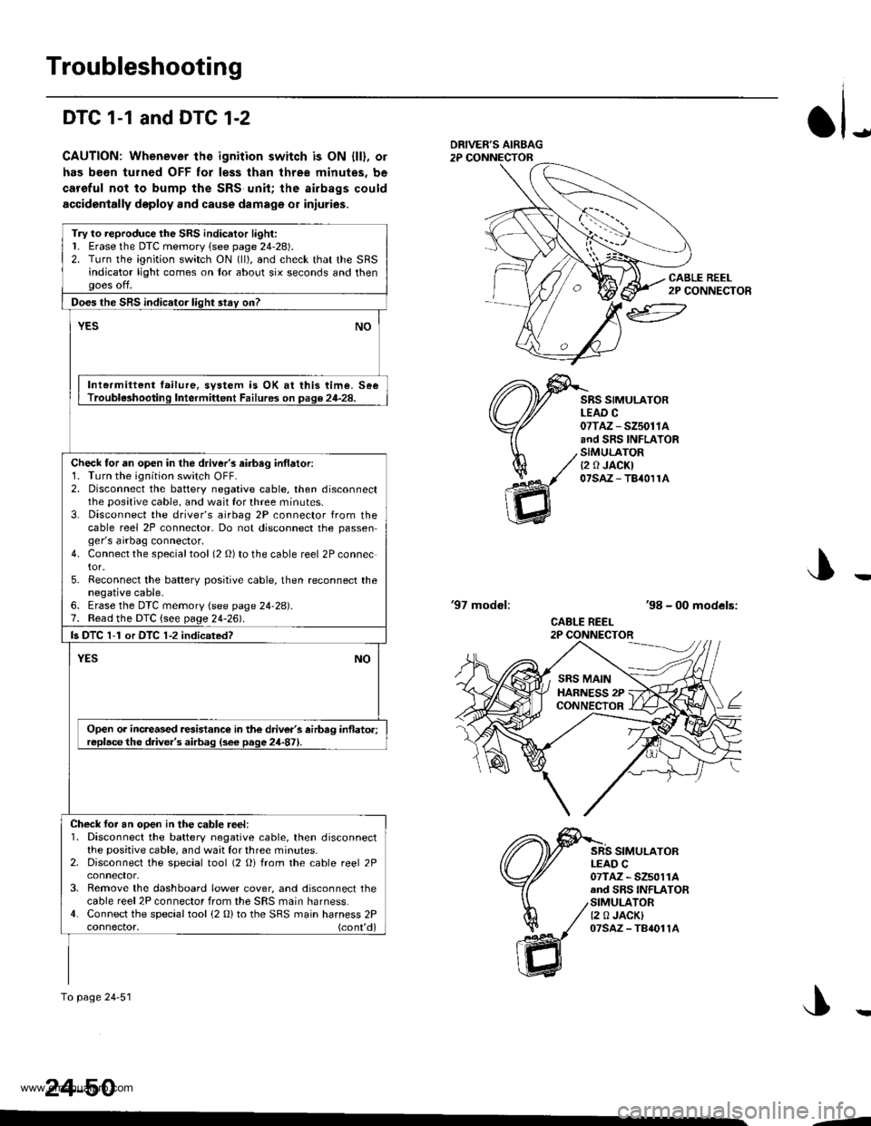
JDRIVEF'S AIRBAG2P CONNECTOR
CABLE REEL2P CONNECTOR
SRS SIMULATORLEAD C07TAZ - SZ5011Aand SRS INFLATORSIMULATORt2 0 JACKI07saz - TB40r1A
'97 modol:'98 - 00 models:
CABLE REEL2P CONNECTOR
SRS SIMULATORLEAD C07TAZ - SZ5011Aand SRS INFLATORSIMULATOR12 0 JACKI07sAz - TB4011A
J
24-50
Try to reproduce the SRS indicator light:1. Erase the DTC memory (see page 24-28).2. Turn the ignition switch ON (ll), and check that the SRSindicator light comes on tor about six seconds and thenooes off.
Does the SRS indicator liqht stav on?
YESNO
Intermiltent failure, svstem is OK at this time. SeeTrouble3hooting Intermittent Failures on page 24-28.
Check tor an open in the driver's airbag inflatori1. Turn the ignition switch OFF-2. Disconnect the battery negative cable, then disconnectthe positive cable, and wait for three minutes.3. Disconnect the driver's airbag 2P connector from thecable reel 2P connector- Do not disconnect the passenger's airbag connector.4. Connect the specialtool (2 O) to the cable reel 2P connector.5. Reconnect the batterv positive cable, then reconnect thenegative cable,6. Erase the DTC memory (see page 24-28).7. Read the DTC {see page 24-261.
ls DTC 1-1 or DTC 1-2 indicsted?
NOYES
Open or increased resistance in the driver's airbag inflato.;replacethe d.ive.'s airbag (s6e page 24-871.
Check foi an ooen in the cable reel:1. Disconnect the battery negative cable, then disconnectthe positive cable, and waat for three minutes.2. Disconnect the special tool (2 Oi from the cable reel 2P
3. Remove the dashboard lower cover, and disconnect thecable reel 2P connector from the SRS main harness.4. Connect the special tool (2 0) to the SBS main harness 2Pconnector, (cont'd)
To page 24'51
SRS MAINHARNESS 2PCONNECTOR
--
www.emanualpro.com
Page 1349 of 1395
Troubleshooting
DTC 1-3
CAUTION: Whonovor the ignition switch is ON (ll), or
has been turnod OFF for less thsn three minutss. be
caroful not to bump the SRS unit; tha ailbags could
accidentally doploy and cau3o damage or iniuries.
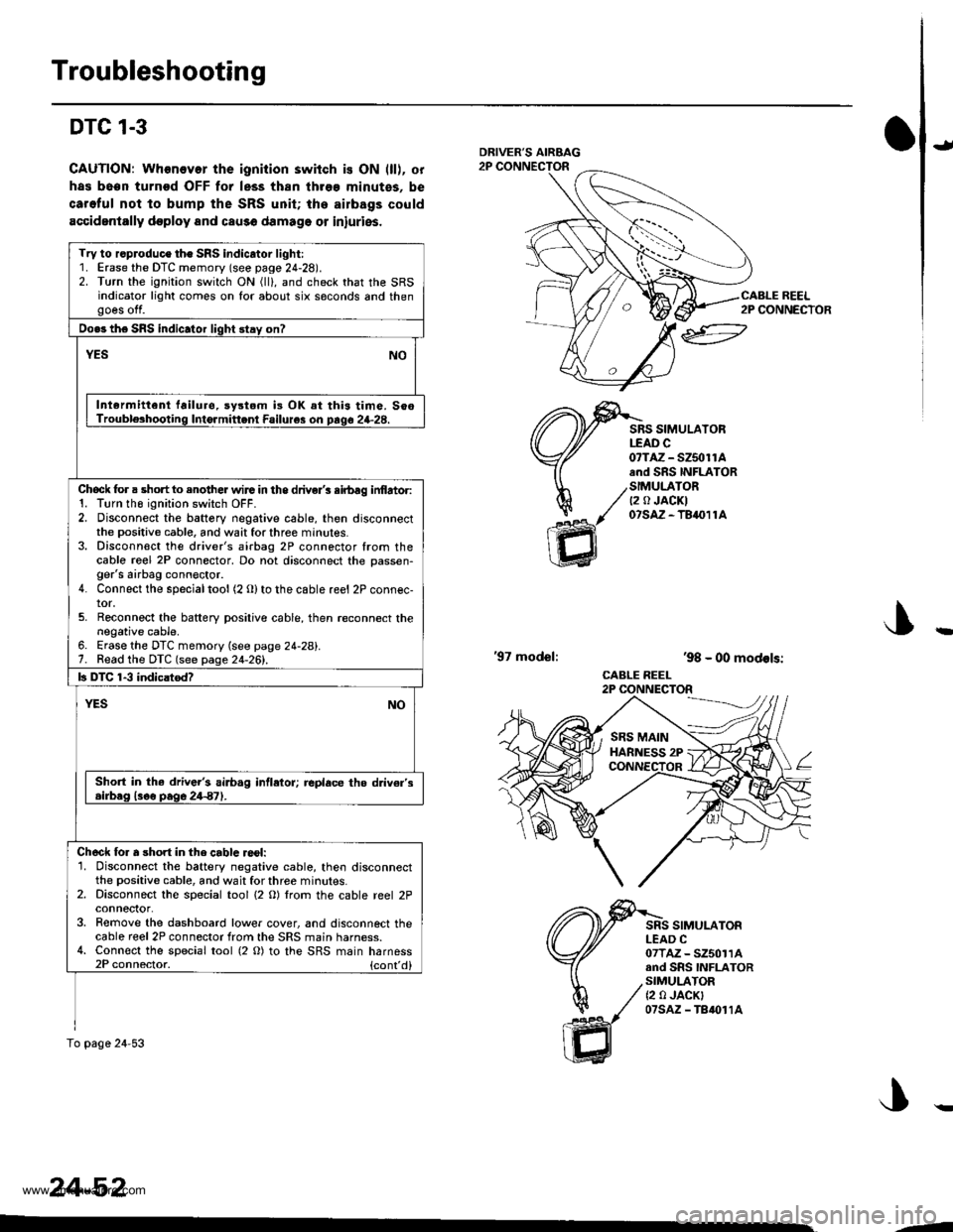
J
ffi
SRS SIMULATORtfAD c0?TAZ - SZ5olrAand SRS INFLATOR
/SIMULATOR/ Q a JACKI
/' 07s,A-TB411A
,98 - 00 models:
CABLE REEL2P CONNECTOR
'97 model:
SRS SIMULATORLEAD C07TAZ - SZ50114and SnS INFLATORSIMULATOR{2 0 JACK}07sAz - TB{011A
Try to r.produce the SRS indicator light:1. Erase the DTC memory (see page 24-28).2. Turn the ignition switch ON (ll), and check that the SRSindicator light comes on for about six saconds and thengoes off.
Do.s the SRS indic.tor light stay on?
NOYES
Intermittenl failuro. sy3tom i3 OK at this time. SooTrouble3hooting Intormittenl Failure3 on prqo 24-28.
Chock for a short to enother wirG in the driver's sirbag inf,artor:1. Tlrn tho ignition switch OFF.2. Disconnect the battery negative cable, then disconnectthe positive cable, and wait for three minutes.3. Disconn€ct the driver's airbag 2P connector from thecablo re€l 2P connector, Do not disconnect the oassen-ger's airbag conn€ctor.4. Connect the specialtool (2 Olto the cable reel 2P connec-tor.5. Reconnect the baftery positive cable, then reconnect thenegative cable.6. Erase the DTC memory (see page 24-28).7. Read the DTC (see page 24-261.
b DTC 1-3 indicatod?
YESNO
Sho.t in the driv6r's airb.g intletor; replace the d v€r's.irb.g l3oo pag6 24€7).
Ch6ck lor a short in the cablc reol:'1. Disconnect the battery negative cable, then disconnectthe positive cable, and wait for three minutes.2. Disconnect the special tool {2 O) lrom the cable reel 2Pconneclor.3. Remove the dashboard lower cover, and disconnect thecable reel 2P connector from the SRS main harness.4. Connect the special tool (2 O) to the SRS main harness2P connector. {cont'd}
To pago 24-53
24-52
2P CONNECTOR
--
www.emanualpro.com
Page 1351 of 1395
Troubleshooting
DTC 1-4
CAUTION: Whonover the ignition switch is ON (ll), or
has boen turned OFF for less than throe minutos, bs
carelul nol to bump tho SRS unit; the airbags could
accidentally deploy and cause damago or iniuri63.
ial
ltl
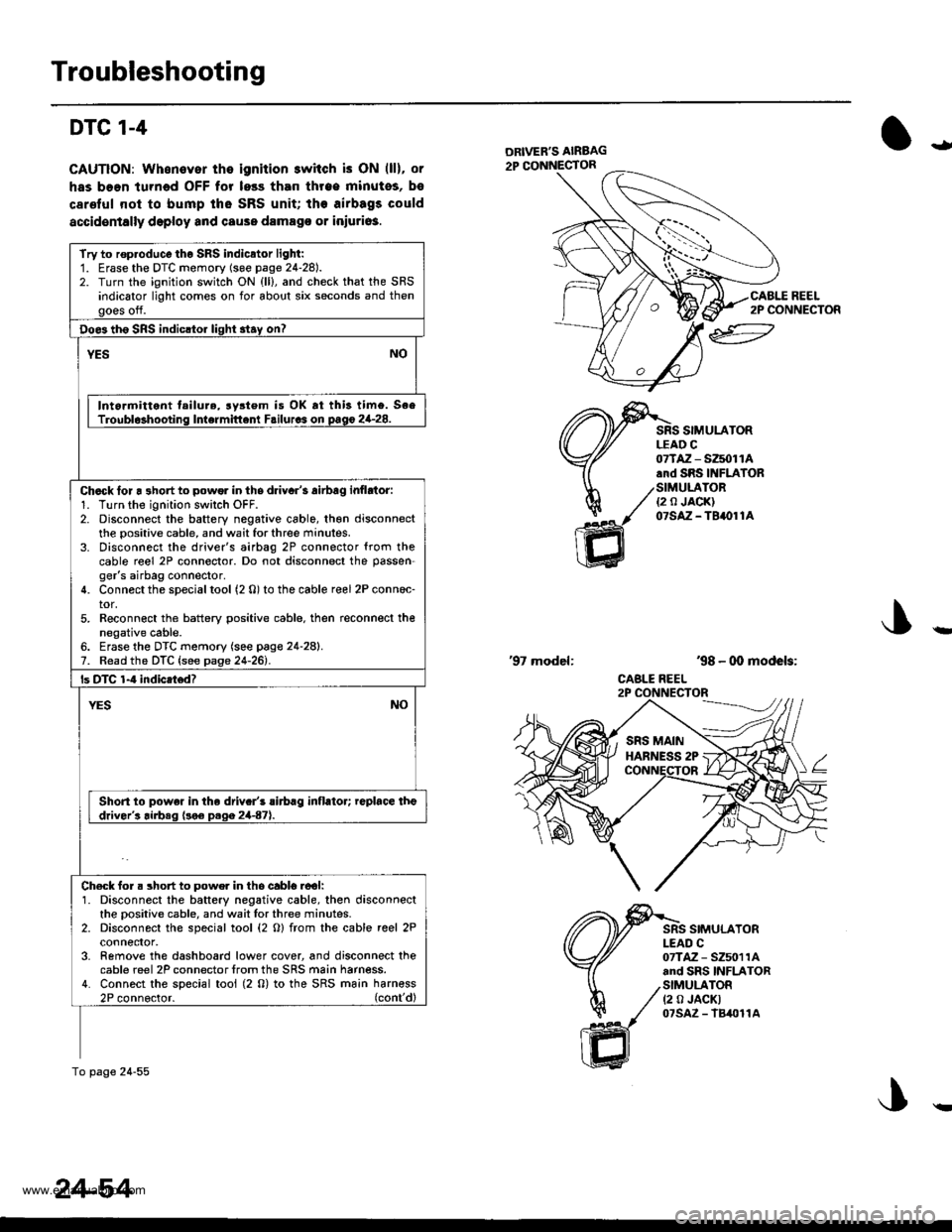
REEL2P CONNECTOR
SIMULATORLEAD C
ffi
07TAZ - SZ5011A.rd SRS INFIATOR
/SIMULATOR./ ea JA0KI
1( otstz-terore
'98 - 00 models:
CABLE REEL
'97 model:
SIMULATORI-EAD C07TAZ - SZ5011Aand SRS INFLATORSIMULATOR(2 0 JACKT07sAz - lB4011A
Try to rop.oduco tho SRS indicator light:1. Erase the DTC momory (soe page 24-28).2. Turn the ignition switch ON {ll}, and check that the SRSindicator light comes on for about six seconds and thengoes off.
Doe3 th6 SRS indicltor light 3tay on?
YESNO
Intormittent tailure, rystem is OK rt this timo. SeeTroubl$hooting Intermittent Failurcs on pago 2G28.
Chack lor a 3hort to powor in ths driyar's airbag inflrtor:1. Turn the ignition swilch OFF.2. Disconnect the battery negative cable, th€n disconnectthe positive cable, and wait for three minutes.3. Disconnect the driver's airbag 2P connector {rom thecable reel 2P connector. Do not disconnect the passen-ger's airbag connector.4. Connect the special tool (2 0) to the cable reel 2P conn6c-tor,5. Reconn€ct the battery positive cable. then reconnect thenegative cable.6. Erase the DTC memory (see page 24-28).7. Read the DTC {see page 24-261.
ls DTC 1-4 indicatod?
NOYES
Short to powe. in the driv.r's rirbrg inflator; replace theddver's airbeq (!o€ D.qa 2447).
Ch€ck for. short to powe. in tho cabl6.ool:1. Disconnect the battery negative cable, then disconnectthe oositive cable, and wait lor three minutes.2. Disconnect the special tool (2 O) from the cable reel 2Pconnefior,3- Remove the dashboard lower cover, and disconnect thecable reel 2P connector lrom the SRS main harness.4. Connect the special tool (2 0) to the SRS ma;n harn€ss2P connoctor. (cont'dl
To page 24-55
24-54
!
www.emanualpro.com
Page 1353 of 1395
Troubleshooting
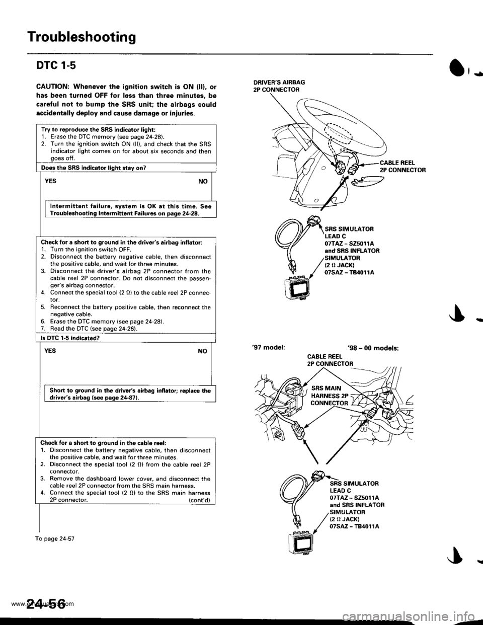
DTC l-s
CAUTION: Whenever tho igniiion switch is ON {ll), or
has been lurned OFF for loss lhan thrse minules, be
caretul not to bump the SRS unit; the airbags could
accidentally deploy and cause damage or iniuries.
O'-
DRIVER'S AIRBAG2P CONNECTOR
'97 model:
SRS SIMULATORLEAD C07TAZ - SZ50r1A.nd SRS INFLATORSIMULATOR{2 0 JACK)07sAz - TBaolrA
SRS SIMULATORLEAO C07TAZ - SZ5011Aand SRS INFLATORSIMULATORt2 0 JACKI07sAz - TB{01rA
ar
h/
ffi
'98 - 0O models:
CABLE REEL2P CONNECTOR
Try to reproduce the SRS indicator light:1. Erase the DTC memory (see page 24-28).2. Turn the ignition switch ON lll), and check that the SRSindicator light comes on for about six seconds and thengoes off.
Doos tho SRS indicator liqht stav on?
YESNO
Inte.mittent tailure,3y3tem is OK at this timo. 506Troubleshooling Intermittent Failures on Daq€ 24-28.
Check tor a short to ground in the driver's ai.bag intlator:1. Turn the ignition switch OFF.2. Disconnect the battery negative cable, then disconnectthe positive cable, and wa:l for three minutes.3. Disconnect the driver's airbag 2P connector from thecable reel 2P connector, Do not disconnect the passen,ger's airbag connector.4. Connect the special tool {2 O} to the cable reel 2P connec-tor.5. Reconnect the battery positive cable. then reconnect thenegative cable.6. Erase the DTC memory (see page 24 28).7. Read the DTC lsee page 24-261.
ls DTC 1-5 indicated?
YESNO
Short to ground in the driver's airbag inflator; replace thedriver's airbag (s6e page 24-871.
Chock for a short to ground in the cablo reel:1. Disconnect the battery negative cable, then disconnectthe positive cable, and wait for three minutes.2. Disconnect the special tool i2 O) from the cable reel 2P
3. Remove the dashboard lower cover, and disconnect thecable reel 2P connector from the SRS main harness.4. Connect the special tool {2 O) to the SRS main harness2P connector. (cont'd)
To page 24-57
24-56
CAALE REEL2P CONNECTOR
J..
.J
www.emanualpro.com
Page 1357 of 1395
Troubleshooting
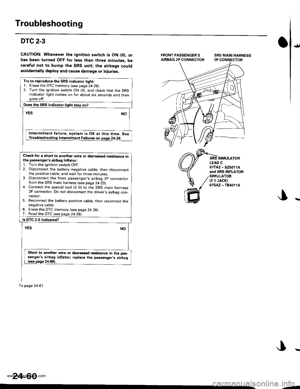
DTC 2-3
CAUTION: Whenevor the ignition switch is ON { }, orhas been turned OFF for less than three minutes, becareful not to bump the SRS unit; lhe airbags couldaccidentally deploy and causo damage or iniuries.
{J
SIMULATORLEAD C07TAZ - SZ50I1Aand SRS INFLATOR
/STMULATOR/ I2n JACKI
y' 07sAz -fB�1011A
ffi
SRS MAIN HARNESS
Try to reproduce the SRS indicator light:1- Erase the DTC memory {see page 24 28).2. Turn the ignition switch ON (ll), and check that the SRSindicator light comes on for about six seconds and thengoes off.
Does the SRS indicator light stay on?
YESNO
Intermittont failur€, syslem is OK at this time. 560T.oubloshooting lntormittent Failur6 on page 24-28.
Check for a short to another wiro or decreased resbtanc€ inthe pa$€nger's airbag inflator:1. Turn the ignition switch OFF.2. Disconnect the battery negative cable, then disconnectthe positive cable, and wait for three minutes.3. Disconnect the front passenger's airbag 2P connectorfrom the SRS main harness (see page 24-23).4. Connect the special tool (2 O) to the SRS main harness2P connector. Do not disconnect the driver,s airbag con-nector.5. Reconnect the battery positive cable, then reconnect thenegative cable.6. Erase the DTC memory (see page 24 28i.7. Read the DTC (see page 24-26).
ls DTC 2-3 indicated?
NOYES
Short to another wir6 or decaea3€d r€aktance in the oas-senger's airbag intlatoi; replac€ the passenger's airbag{see pago 24-8t1.
To page 24 61
24-60
,-
www.emanualpro.com
Page 1359 of 1395
Troubleshooting
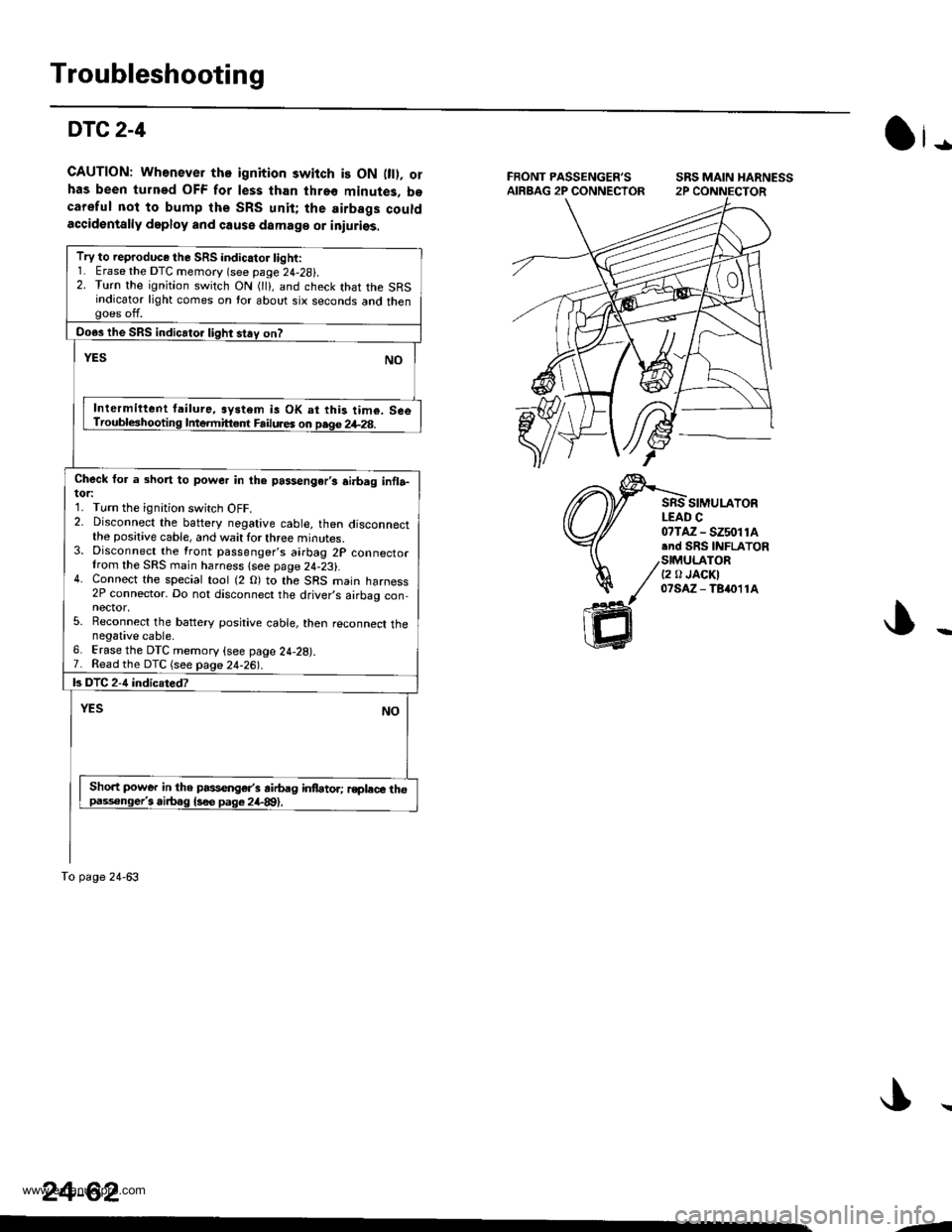
DTC2-4
GAUTION: Wh€never tho ignition switch is ON 0t). orhas been turned OFF for less than threo minutes, bocareful not to bump the SRS unit; the airbags couldaccidentally deploy and cause damaga or iniuriss.
SRS MAIN HARNESS
SIMULAYORLEAD C
Ot-
07TAZ - SZ5011A.nd SRS INFLATOR
/stMU|_ATOR/ t2 tr JAoKI
// olsAz-Tsn11A
ffi
Try to reproduce the SRS indicator light:1. Erase the DTC memory (see page 24-28i.2. Turn the ignition switch ON (lli, and check that the SRSindicator light comes on tor about six seconds and thengoes off.
Do€s the SRS indicator light stay on?
YESNO
Inlermittent tailure, system is OK at this tim€. SceTroubleshooting Intermitt€.f Failures on page 2+28.
Check for a short to power in the passengar,s ai.bag infla-tor:1. Turn the ignition switch OFF.2. Disconnect the baftery negative cable, then disconnectthe positive cable, and wait for three minutes.3. Disconnect the front passenger's airbag 2P connectorIrom the SRS main harness lsee page 24-23).4. Connect the special tool (2 O) to the SRS main harness2P connector. Do not disconnect the driver,s airbag con,nector,5. Reconnect the battery positive cable, then reconnect thenegative cable.6. Erase the DTC memory (see page 24-28).7. Read the DTC (see page 24-26|'.
ls DTC 2-4 indicsted?
YESNO
Sho.t power in the passenger's airbag infator; rsplece thopaisonge/i airbag {s€e pag€ 2il-89).
To page 24-63
24-62
--
www.emanualpro.com
Page 1363 of 1395
Troubleshooting
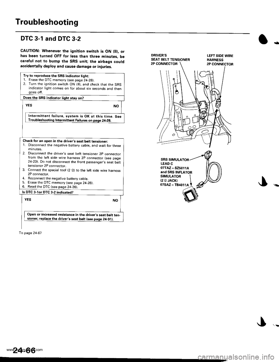
DTC 3-1 and DTC 3-2
CAUTION: Whenever the ignition switch is ON flll, orhas been turned OFF for less than three minutes, b€careful not to bump th€ SRS unit; the airbags couldaccidenlally deploy and cause damage or iniuries.
DRIVER'SSEAT BELT TENSIONERLEFT SIOE WIREHARNESS2P CONNECTOR2P CONNECTOR
-
\
SRS SIMULALEAD C07TAZ - SZ501rAand SRS INFLATORSTMULAToR It2 0JACKI IoTsaz - TB4ot lA t
24-66
Try to reproduce the SRS indicatoi light:1. Erase the DTC memory (see page 24-29).2. Turn the ignition switch ON 1 ), and check that the SRSindicator light comes on for about six seconds and thengoes off.
Does the SRS indicaior lighr stay on?
YESNO
Intermittent failure, system is OK at this time. SeeTroubleshooting lfiermittent Failu.6s on page 24-28.
Check tor an open in the driver's seat b6lt tensioner:1. Disconnect the negative battery cable, and wait lor threeminutes.2. Disconnect the drave/s seat belt tensioner 2p connectorfrom the left side wire harness 2P connector (see page24-23). Do not disconnect the lront passenger,s seat belttensioner 2P connector.3. Connect the special tool {2 O) to the left side wire harness2P connector,4. Reconnect the negative baftery cable5. Erase the DTC memory {see page 24,28).6. Read the DTC (see page 24-26).
ls OTC 3-1or DTC 3-2 indicatedT
YESNO
Open or increased resistance in the d.iver's seat belt ten-sioner; replace the driver's seat belt {see page 2il-91).
To page 24 67
www.emanualpro.com
Page 1367 of 1395
Troubleshooting
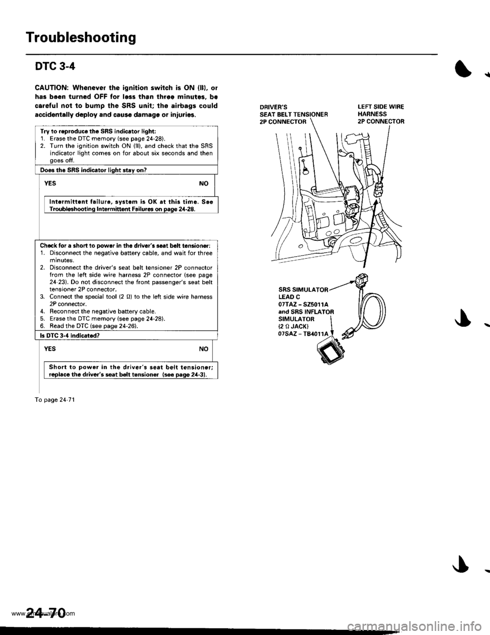
DTC 3-4
CAUTION: Whenever the ignition switch is ON (lll, ol
has been turned OFF for l6ss than thr6e minutes, b€
careful not to bump the SRS unit; lho airbags could
accidentally deploy and caus€ damage or iniuries.
{
DRIVER'SSEAT BELT TENSIONER2P CONNECTOR
LEFT SIDE WIREHARNESS2P CONNECIOR
SRS SIMULATORLEAD C07TAZ - SZ5011Aand SRS INFLATORSIMULATOR I{2 o JACK} Iozsaz - tamrrl i
Try lo reproduco th6 SRS indicator light:1. Erasethe DTC memory (see page 24-28).2. Turn the ignition switch ON (ll), and check that the SRSindicator light comes on for about six seconds and thenooes off,
Doe3 the SRS indicator liqht stav on?
NOYES
Intcrmitt.nt f.ilur., iystem is OK at this time. SoeTroubla3hooting Intermittent Failurca on Dage 24-28.
Checklor a shortlo Dowar in the driver'3 3€at beh tonsioncr:1. Disconnoct the negative battery cable, and wait for threeminutes.2. Disconnect the driver's seat belt tensioner 2P connectorfrom the left side wire harness 2P connector (see page24 23). Do not disconnect the front passenger's seat belttensioner 2P connector,3. Connect the special tool {2 0) to the left side wire harness2P connector.4. Reconnect the negative battery cable.5. Erase the DTC memory {see page 24-28).6. Read the DTC (see page 24-26).
ls DTC 3-4 indicsted?
NOYES
Short to powar in the d.iver's seat belt tensioner;replace the d.iver's seat belt tensione. {3ee pago 2il-31.
To page 24'71
24-70
www.emanualpro.com