rear bumper HONDA CR-V 2000 RD1-RD3 / 1.G Workshop Manual
[x] Cancel search | Manufacturer: HONDA, Model Year: 2000, Model line: CR-V, Model: HONDA CR-V 2000 RD1-RD3 / 1.GPages: 1395, PDF Size: 35.62 MB
Page 22 of 1395
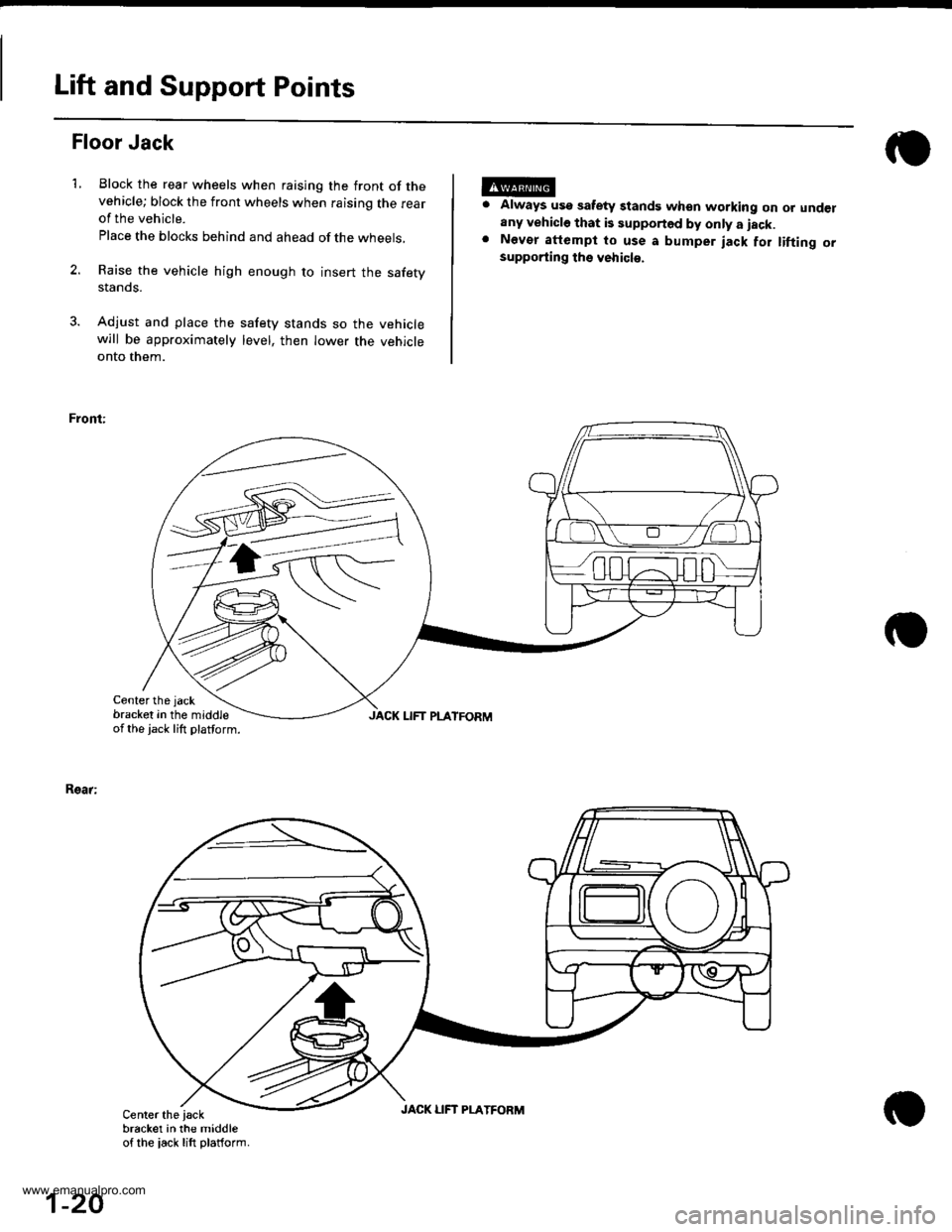
Lift and Support Points
1.
Floor Jack
Block the rear wheels when raising the front of thevehicle; block the front wheels when raising the rearof the vehicle.
Place the blocks behind and ahead of the wheels,
Raise the vehicle high enough to insert the safetystanos.
Adjust and place the safety stands so the vehiclewill be approximately level, then lower the vehicleonto them.
Front:
Center the jack
bracket in the middleof the jack lift platform.
Always usg safety standg when working on or underany vehicle that is supported by only a iack.Nevor attempt to use a bumper jack for tifting orsupporting ths vehicl€.
Rsar:
JACK LIFT PLATFORM
Center the iackbracket in the middleof the iack lift platform.
1-20
JACK LIFT PLATFORM
www.emanualpro.com
Page 23 of 1395
Towing
lf the vehicle needs to be towed, call a professional
towing service. Never tow the vehicle behind another
vehjcle with just a rope or chain. lt is very dangerous.
Emergency Towing
There are three popular methods of towing a vehicle.
Flat-bed Equipment - The operator loads the vehicle on
the back of a truck. This is the best way of transporting the
vehicle.
Wheel Lift Equipment - The tow truck uses tlvo pivoting
arms that go under the tires lfront or rear) and lifts them
off the ground. The other two tires remain on the
ground. The vehicle's suspension and body can be
seriously damaged if this method of towing is attempted.
Sling-type Equipment - The tow truck uses metal cables
with hooks on the ends. These hooks go around parts of
the frame or suspension and the cables lift that end of
the vehicle off the ground. The vehicle's suspension and
body can be seriously damaged if thjs method of towing
is attempted. This methed of towing the CR-V is
unaccePtable.
The onlv recommended way of towing the CR-V is on a
flat-bed truck. Two wheel drive CR-V's may also be
towed with all four wheels on the ground.
Towing the four-wheel dlive CR-v with only two
wheels on the ground will damage parts of the 4wD
system. It this vehicle is damaged, it should be towed
on a flat-bed truck ol trailel.
It the 2 wheel drive CR-v is towed wiih all tour wheels
on the ground, do the following:
Manual Transmission
. Release the parking brake.
. Shift the transmission in Neutral
Automatic Transmission
. Release the parking brake.
. Sta rt the engine.
. Shift to lD.l position. then E position.
. Turn off the engine.
lmproper towing preparation will damage the
transmission. Follow the above procedure exactly. lf
you cannot shift the transmission or start the engine,
the vehicle must be transported on a flat-bed truck.
lf the vchicle is towed with four wheels on the ground,
il is best to tow the vehicle no larther than 50 miles (80
km), and keep the speed below 35 mph {55 km/h).
Trying to lift or tow the vehicle by ihe bumpers will
cause serious damage. The bumpers ale not dosigned
to support the vehicle's weight.
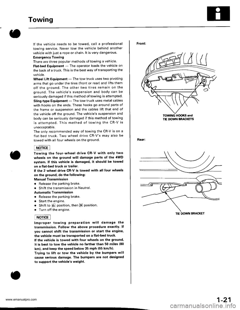
Front:
Rear:
lOwlNG HOOKS .ndTIE DOWN BRACKETS
TIE DOWN BRACKET
1-21
www.emanualpro.com
Page 24 of 1395
Service Precautions
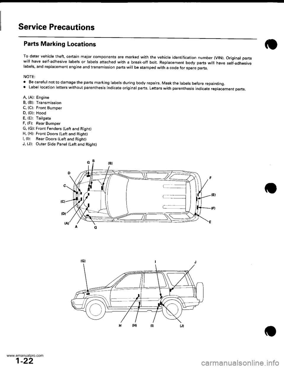
Parts Marking Locations
To deter vehicle theft, cenain major components are marked with the vehicle identification number {VlN). Original partswill have self-adhesive labels or labels attached with a break-off bolt. Replacement body parts will have self-adhesivelabels, and replacement engine and transmission parts will be stamped with a code tor spare parts.
NOTE:
. Be careful nottodamagethe parts marking labelsduring body repairs. Maskthe labels before repainting.' Label location letters without parenthesis indicate original parts. Letters with parenthesis indicate replacement pans.
A, (A): Engine
B, (B): Transmission
C, (C): Front Bumoer
D, (D); Hood
E, (E): Tailgate
F, (F): Rear Bumper
G, (G): Front Fenders (Lefr and Right)H, {H): Front Doors (Left and Right}
l, (l): Rear Doors (Left and Right)
J, (J): Outer Side Panel (Left and Right)
1-22
www.emanualpro.com
Page 982 of 1395
Body
Bumpers
Front Bumper Removal and
fnstaflation .........20-72
Rear Bumper Removal and
fnstaflation .........20-74
'Dashboard
lnstrument Panel Removal and
lnstallation .........20-47
Driver's Dashboard Lower Cover and
Knee Bolster Removal and
Installation .........20-48
Glove Box Removal and
lnstallation .........20-49
Center Pocket Removal and
lnstallation .........20-49
Center Dashboard Lower Cover
Removal and lnstallation ............ 20-50
Center Panel Removal and
lnstallation .........20-50
Power Window Switch Removal and
lnstallation .........20-51
Center Air Vent Removal and
lnstallation .........20-51
Side Air Vent Removal and
fnstallation .........20-52
Side Defogger Trim Removal and
fnstallation .........20-52
Dashboard Removal and
lnstallation .........20-53
Dashboard Frame Replacement ..... 20-55
Doors
Component Location Index
Front Door ,,...,,,,20-2
Rear Door ...........20-4
Tailgate Door ................................ 20-6
Fenderwell
Front Wheelwell Protector
Replacement .....20-89
Inner Fender Replacement .,.....,.,.... 20-89
Rear Wheelwell Protectol
Replacement .....20-90
Fuel Pipe Protector Replacement ... 20-90
Rear Air Outlet Replacement .......... 20-91
*Frame Repair Chart .............................. 20-106
Front Grille
Repf acement .........20-77
Glass
Component Location Index ............ 20-29
Hood
Replacement ......,,,20-75
Adjustment ............20-76
*lnterior Trim
Component Location Index ............ 20-40
Mirrors
Component Location Index .........,,, 20-26
Moldings
Roof Molding Replacement ............ 20-84
Door Moldings Replacement .......... 20-85
Openers
Component Location Index ............ 20-92
Rear Hatch Glass
Replacement .........20-74
Disassembly and Reassembly ........ 20-79
Adiustment ............20-81
Rear Weatherstrip Replacement .... 20-83
Seats
Component Location Index ............ 20-56
Side Sill Panel
Repfacement .........20-87
Spare Tire Cover
Emblem Installation ........................ 20-88
Sub-frame ..................20-104
Wiper/Washer
Component Location lndex ,,,,,....... 20-97
www.emanualpro.com
Page 1055 of 1395
Bumpers
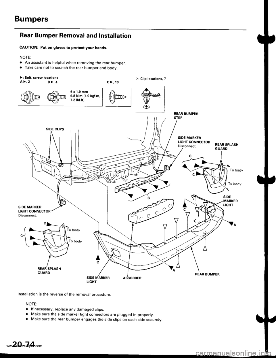
Rear Bumper Removal and Installation
CAUTION: Put on gloves to proteqt your hands.
NOTE:
. An assistant is helpful when removing the rear bumper.. Take care not to scratch the rear bumDer and bodv.
>: Boli, screw locationsa>,2B>,4c>, 10>: Clip locelions, 7
rgfi\\* ffi\\-. 3il;l-'lln*n,..,
WJ/* Y)f t.2tbtftl
.f-.' I
0f'" I trl-l.Kl
-l
BEAR BUMPERSTEP
SIOE MARKERLIGHT CONNECTOFDisconnect.REAR SPLASHGUARD
To body
To body
SIDEMARKERLIGHT
To body
To body
REAR BUMPER
Installation is the reverse of the removal procedure.
NOTE:
. lf necessary, replace any damaged clips.. Make sure the side marker light connectors are plugged in properly.. Make sure the rear bumper engages the side clips on each side securely.
20-74
LIGHT
www.emanualpro.com
Page 1071 of 1395
Fenderwell
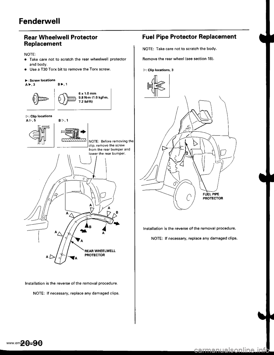
Rear Wheelwell Protector
Replacement
NOTE:
. Take care not to scratch the rear wheelwell protector
and body.
. Use a T30 Torx bit to remove the Torx screw.
>: Screw locationsa>,3
I
6him" lY/
>: Clip locationsA >,5 B>, 1
B>, I
,.{\
F ),@Y-./
6x1.0mm9.8 N.m {1.0 kgl.m.7.2 rbtft)
YnTn | |
/'d)Ul | +['Tl+l
\=lHl | _H_l
tlrflJ | - INoTE: Before removinsthe- | lclip. remove the screw
lnstallation is the reverse of the removal procedure.
NOTE: lf necessary, replace any damaged clips.
from the rear bumper andlower the rear bumper,
20-90
Fuel Pipe Protector Replacement
NOTE: Take care not to scratch the body.
Remove the rear wheel (see section 18).
>: Clip locations,3
/ll
qK
1l
lnstallation is the reverse of the removal Drocedure.
NOTE: lf necessary. replace any damaged clips.
www.emanualpro.com
Page 1072 of 1395
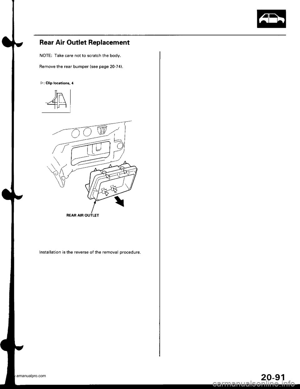
Rear Air Outlet Replacement
NOTE: Take care not to scratch the body.
Remove the rear bumper (see page 20-74).
>: Clip locations, 4
Installation is the reverse of the removal Drocedure.
Tt-
A\-T[-r
20-91
www.emanualpro.com
Page 1080 of 1395
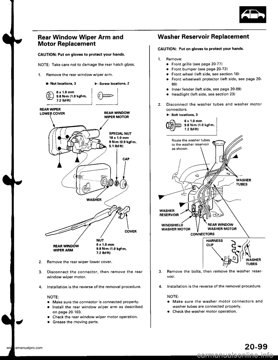
Rear Window Wiper Arm and
Motor Replacement
CAUTION: Put on gloves to protect your hands.
NOTE; Take care not to damage the rear hatch glass.
1. Remove the rear window wiper arm.
a: Nut loc.tion!, 3>: Scaow locationa, 2
REAR WINDOWWIPER MOIOR
REAR WIPERCOVER
REARWIPER ARM
6x1.0mm9.8 N.m 11.0 kgt'm,7.2 tbf.ftl
SPECIAL NUT18 x 1.0 mm9 N.m 10.9 kgt m,5. r tbt.ftl
NUT6x 1.0mm9.8 N.m {1.0 kgt.m,?.2 tbfftl
Remove the rear wiper lower cover.
Disconnect the connector, then remove the rear
window wiper motor.
Installation is the reverse of the removal procedure.
NOTE:
. Make sure the connector is connected properly.
. Install the rea. window wiper arm as described
on page 20-103.
. Check the rear window wiper motor operation.
. Grease the moving parts.
@rrc
Washer Reservoir Replacement
GAUTION: Put on gloves to protect your hands.
1. Remove:
. Front grille (see page 20-771
. Front bumper (see page 20-721
. Front wheel {left side, see section 18)
. Front wheelwell protector (left side, see page 20-
89)
. Inner fender (left side, see page 20-89)
. Headlight (left side, see section 23)
2. Disconnect the washer tubes and washer motor
connectors.
>: Bolt locations, 3
6x1.0mm9,8 N.m 11.0 kgt.m,7.2 tbt.ftl
Route the washer tubesto the washer teservoir
WASHERRESERVOIR
WINOSHIELOWASHER MOTON
CONNECTORS
3. Remove the bolts, then remove the washer reser-
votr,
4. Installation is the reverse of the removal procedure.
NOTE:
a Make sure the washer motor connectors and
washer tubes are connected properly.
. Check the washer motor operation.
HARNESS / tcLrP C-(fu
- S(ilq
s{J
l' wrsHER
20-99
www.emanualpro.com
Page 1171 of 1395

Gonnector ldentification and Wire Harness Routing
How to ldentity Connectors:
ldentification numbers have been assigned to all connectors, The number is preceded by the letter "C" for connectors.
"G" for ground terminals or "T" for non-ground terminals.
Location
HarnessEngine CompartmsntDashboardOthers lFloor, Door,
8oof, Tailgate)
Starter cableT1, T2 and @
Battery ground cableG1 and O
Engine ground cableT3
Transmission ground cableT4
G3
Engine wire harnessC101 through C137
T101 and T102
G101
Engine compartment ware harnessC201 through C218
G201 and G202
Under-hood ABS fuse/relay box
wire harness
t5ano9
Main wire harnessC301 through C309
C351 through C361
C401 through C447
G401 and G402
Dashboard wire harnessC501 through C524 (C525)
G501
Left side wire harnessC551 through C581
G551, G552 and G553
Right side wire harnessC601 through C605
lnterior wire harnessC701 through C703
Rear bumper wire harnessC641 through C643
Heater sub-harnessC731 through C740
Secondary heated oxygen sensor
sub-harness
C721 through C722
Combination switch sub-harnessC751 through C760
Driver's door wire harnessC661 through C667
Front passenger's door wire harnessC6Tl through C676
Left rear door wire harnessC681 through C684
Right rear door wire harnessC69'l through C694
Rear wire harnessC611 through C520
Tailgate wire harnessC631 through C634
G631
SRS main harnessC801 through C808
G801
High mount brake light sub-harnessC651 through C653
Fuel tank oressure sensor sub-harnessC645 through C647
www.emanualpro.com
Page 1176 of 1395
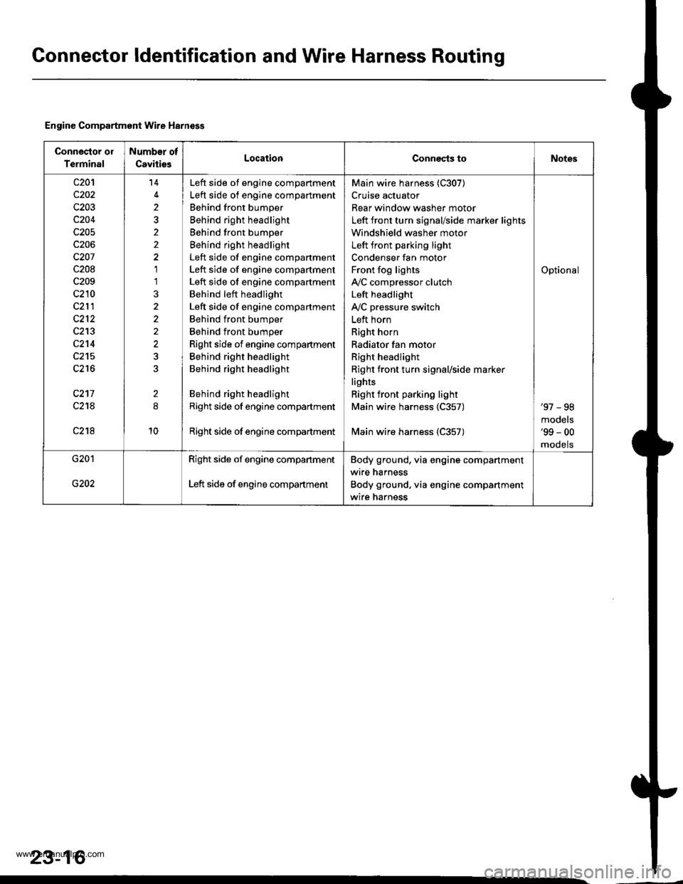
Gonnector ldentification and Wire Harness Routing
Engine Compartment Wire Harness
Connector ol
Terminal
Number of
CavitiesLocationConnects toNotes
c20'l
c202
c203
c204
c205
c206
c207
c208
c209
c210
c212
c213
c2't4
c215
c216
c217
c21A
c218
14
2
2
1'l
2
10
Left side of engine compartment
Left side of engine compartment
Behind front bumper
Behind right headlight
Behind front bumper
Behind right headlight
Left side of engine compartment
Left side of engine compartment
Left side of engine compartment
Behind left headlight
Left side of engine compartment
Behind front bumper
Behind front bumper
Right side of engine compartment
Behind right headlight
Behind right headlight
Behind right headlight
Right side of engine compartment
Right side of engine compadment
Main wire harness (C307)
Cruise actuator
Rear window washer motor
Left front turn signal/side marker lights
Windshield washer motor
Left front parking light
Condenser fan motor
Front fog lights
IVC compressor clutch
Left headlight
IVC pressure switch
Left horn
Right horn
Radiator fan motor
Right headlight
Right front turn signal/side marker
lights
Right front parking light
Main wire harness 1C357)
Main wire harness (C357)
Optional
'97 - 98
models'99 - 00
mooets
G201
G202
Right side of engine companment
Left side of engine compartment
Body ground, via engine compartment
wire harness
Body ground, via engine compartment
wire harness
23-16
www.emanualpro.com