seats HONDA CR-V 2000 RD1-RD3 / 1.G Workshop Manual
[x] Cancel search | Manufacturer: HONDA, Model Year: 2000, Model line: CR-V, Model: HONDA CR-V 2000 RD1-RD3 / 1.GPages: 1395, PDF Size: 35.62 MB
Page 15 of 1395
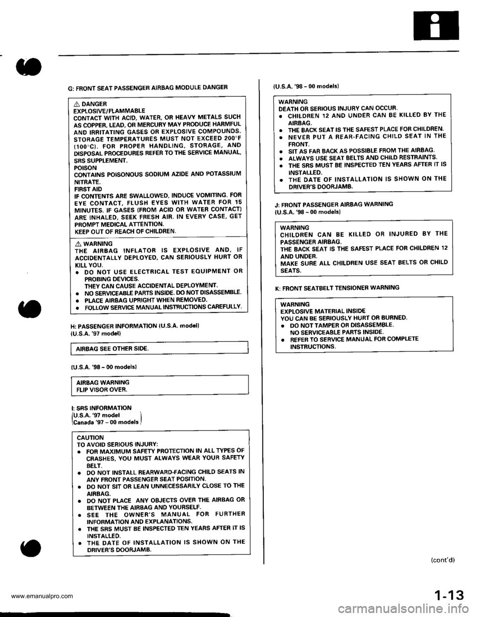
G: FRONT SEAT PASSENGER AIRBAG MODULE DANGEN
A DANGEREXPLOSIVE/FLAMMABLECONTACT WITH ACID, WATER. OR I{EAVY METALS SUCH
AS COPPER. T.EAD. OR MERCURY MAY PRODUCE HARMFUL
AND IRRITATING GASES OR EXPLOSIVE COMPOUNDS.
STORAGE TEMPERATURES MUST NOT EXCEED 2OO"F
IlOO'C). FOR PROPER HANDLING, STORAGE, AND
DISPOSAL PROCEDURES REFER TO THE SERVICE MANUAL,
SRS SUPPLEMENT.POTSONCONTAINS POTSONOUS SODIUM AZIDE ANO POTASSIUM
NITRATE.FIRST AIDIF CONTENTS ARE SWALLOWED, INDUCE VOMITING. FOR
EYE CONTACT, FLUSH EYES WITH WATER FOR 15
MINUTES. IF GASES (FROM ACID OR WATEN CONTACT)
ARE INHALEO. SEEK FRESH AIR. IN EVERY CASE, GET
PROMPT MEDICAL ATTENTION.KEEP OUT OF REACH OF CHILDREN.
A WARNINGTHE AIRBAG INFLATOR IS EXPLOSIVE AND, IF
ACCIDENTALLY DEPLOYED, CAN SERIOUSLY HURT OR
KILL YOU.. DO NOT USE ELECTRICAL TEST EOUIPMENT OR
PROBING DEVICES,THEY CAN CAUSE ACCIDENTAL DEPLOYMENT.. NO SERVICEABI-E PARTS lNSlDE. DO NOT DISASSEMBII.
. PLACE AIRBAG UPRIGHT WHEN REMOVEO.
. FOLLOW SERVIC€ MANUAL INSTRUCTIONS CAREFULLY
H: PASSENGER INFORMATION lU S.A. modell
{U.S.A.'97 model}
AIEBAG SEE OTHER SIDE,
{U.S.A.'98 - 00 modelsl
AIRBAG WARNINGFLIP VISOR OVER.
l: SRS INFORMATION
lU.s.A.'97 model ilcanada '97 - 00 mod€ls I
CAUTIONTO AVOID SERIOUS INJURY:. FOR MAXIMUM SAFEW PROTECTION lN ALL TYPES OF
CRASHES, YOU MUST ALWAYS WEAR YOUR SAFETY
8ELT.o OO NOT INSTALL REARWARD-FACING CHILO SEATS lN
ANY FRONT PASSENGER SEAT POSITION.. DO NOT SIT OR LEAN UNNECESSARILY CLOSE TO THE
AIRBAG.. DO NOT PLACE ANY OBJECTS OVER THE AIRBAG OR
BETWEEN THE AIRBAG AND YOURSELF.. SEE THE OWNER'S MANUAL FOR FURTHER
INFORMATION AND EXPLANATIONS. THE SRS MUST BE INSPECTED TEN YEARS AFTER lT lS
INSTALLED.. THE DATE OF INSTALLATION lS SHOWN ON THE
DRIVER'S DOORJAMB.
lU.S.A.'98 - 00 models)
WARNINGDEATH OR SERIOUS INJURY CAN OCCUR'
. CHILDREN 12 ANO UNDER CAN BE KILLED BY THE
AIRBAG.. THE BACK SEAT lS THE SAFEST PLACE FOR CHILDREN.
. NEVER PUT A REAR-FACING CHILD SEAT lN THE
FRONT.o SIT AS FAR BACK AS POSSIBLE FROM THE AIRBAG
. ALWAYS USE SEAT BELTS AND CHll-D RESTRAINTS.
. THE SRS MUST BE TNSPECTED TEN YEAnS AFTER lT lS
INSTALLED.. THE OATE OF INSTALLATION lS SHOWN ON THE
DRIVER'S DOORJAMB.
J: FRONT PASSENGER AIRBAG WARNING
lU.S.A.'98 - 00 models)
WARNINGCHILDREN CAN BE KILLED OR INJURED 8Y THE
PASSENGER AIRBAG.THE BACK SEAT IS THE SAFEST PLACE FOR CI{ILDREN 12
AND UNDER.MAKE SURE ALL CHILDREN USE SEAT BELTS OR CHILD
SEATS.
K: FRONT SEATBELT TENSIONER WARNING
WABNINGEXPLOSIVE MATERIAL INSIDEYOU CAN BE SERIOUSLY HURT OR BURNED,
. DO NOT TAMPER OR DISASSEMBLENO SERVICEABLE PARTS INSIDE.. REFER TO SERVICE MANUAL FOR COMPLETE
INSTRUCTIONS.
(cont'd)
1-13
www.emanualpro.com
Page 62 of 1395
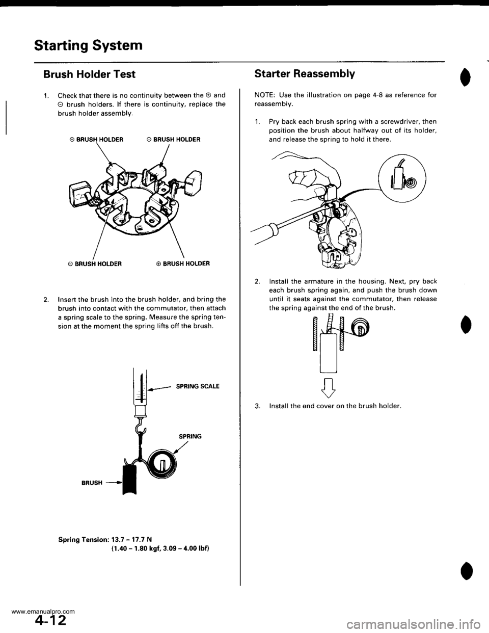
Starting System
Brush Holder Test
1. Check that there is no continuity between the O and
O brush holders. lf there is continuitv, replace the
brush holder assembly.
O BRUSH HOLDER@ BRUSH HOLDER
Insert the brush into the brush holder, and bring the
brush into contact with the commutator, then attach
a spring scale to the spring. Measure the spring ten-
sion at the moment the spring lifts off the brush.
SPRING SCALE
Spring Tension: 13.7 - 17.7 N
(1.40 - 1.80 kgf, 3.09 - 4.00 lbf)
4-12
Starter Reassembly
NOTE: Use the illustration on page 4I as reference for
reassemDty.
1. Pry back each brush spring with a screwdriver, then
position the brush about halfway out ol its holder,
and release the spring to hold it there.
2. Install the armature in the housing. Next, pry back
each brush spring again, and push the brush down
until it seats against the commutator, then release
the spring against the end of the brush.
- E^
F*4#-@
6t taal la
tlll
3. Install the endon the brush holder.
ft
cover
www.emanualpro.com
Page 114 of 1395
Cylinder Head/Valve Train
Speciaf Tools .............6-2
Valve Clearance
Adiustment ............6-3
Valve Seals
Replacement (cylinder head
removal not requiredl ................. 6-5
Crankshaft Pulley and Pulley Bolt
Replacement .........6-7
Timing Belt
I llustrated lndex ............................... 6-8
Inspection ............., 6-9
Tension Adjustment ........................ 6-9
Removal ...........,..... 6-10
lnstallation .............6-11
Crankshaft Speed Fluctuation (CKFI
Sensor
Replacement .........6-13
Cylinder Head
lllustrated lndex ............................... 6-14
Removal .................6-16
Warpage ................6-27
lnstallation ............. 6-30
Camshafts
lnspection ..............6-22
Valves, Valve Springs and Valve Seals
Removal ................, 6-23
lnstallation ............. 6-29
Valve Guides
Valve Movement ............,,,,.,............ 6-25
Replacement .........6-25
Reaming .................6-27
Valve Seats
Reconditioning ......6-28
www.emanualpro.com
Page 141 of 1395
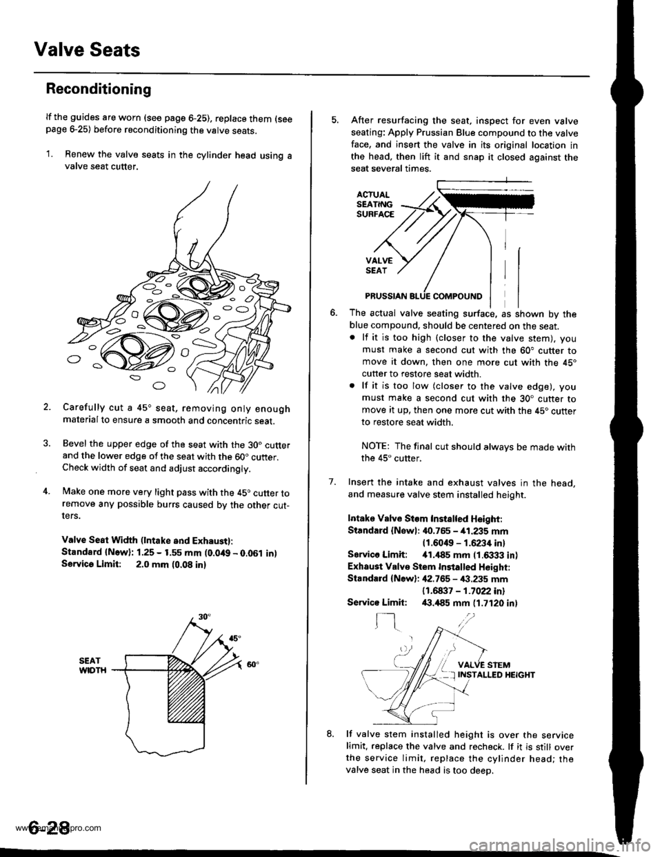
Valve Seats
Reconditioning
lf the guides are worn (see page 6-25), replace them (seepage e25) before reconditioning the valve seats.
1. Renew the valve seats in the cylinder head using avalve seat cutter.
Carefully cut a 45o seat, removing only enoughmaterialto ensure a smooth and concentric seat.
Bevel the upper edge of the seat with the 30. cutterand the lower edge of the seat with the 60" cutter.Check width of seat and adjust acco.dingly.
Make one more very light pass with the 45o cutter toremove any possible burrs caused bv the other cut-ters.
Valve Seat Width (lntake and Exhaust):
Standard {N.w}: 1.25 - 1.55 mm (0.049 - 0.051 in)Servica Limit: 2.0 mm (0.08 in)
o
o
5. After resurfacing the seat, inspect for even valve
seating: Apply Prussian Blue compound to the valve
face, and insert the valve in its original location in
the head, then lift it and snap it closed against the
seat several times.
ACTUALSEATINGSURFACE
VALVESEAT
7.
PRUSSIAN
The actual valve seating surface, as shown by the
blue compound, should be centered on the seat.. lf it is too high (closer to the valve stem), you
must make a second cut with the 60" cutter tomove it down, then one more cut with the 45"
cutter to restore seat width.
. lf it is too low (closer to the valve edge), you
must make a second cut with the 30. cutter tomove it up, then one more cut with the 45. cutter
to restore seat width.
NOTE: The final cut should alwavs be made withthe 45" cutter,
Insert the intake and exhaust valves in the head,
and measure valve stem installed heioht.
Intake Vslve Siem Instslted Height:
Standard {Newl: it0.765 - 41.235 mm
11.6049 - 1.6234 inl
Sarvico Limit: itl.il85 mm (1.6333 in)
Exhaust Valve Stem Installed H6ight:
Standard {New}: 42.755 - €.235 mm
11 .61137 - 1 .7022 inl/(|.,185 mm (1.7120 in)
VALVE STEMINSTALLED HEIGHT
8. lf valve stem installed height is over the servicelimit. replace the valve and recheck. lf it is still overthe service limit. replace the cylinder head; thevalve seat in the head is too deeo.
Servico Limit:
f-]
6-28
www.emanualpro.com
Page 142 of 1395
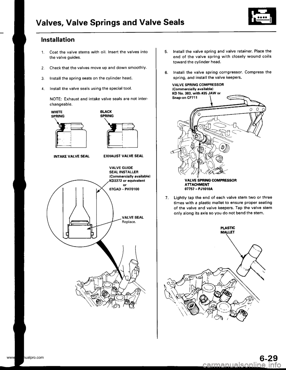
Valves, Valve Springs and Valve Seals
lnstallation
Coat the valve stems with oil. Insert the valves into
the valve guides.
Check that the valves move up and down smoothly.
Install the spring seats on the cylinder head.
Install the valve seals using the special tool.
NOTE: Exhaust and intake valve seals are not inter-
1.
changeable.
WHITESPRING
BLACKSPRING
INTAKE VALVE SEALEXHAUST VALVE SEAL
VALVE GUIDESEAL INSTALLER
lCommercially available)KO3372 or equival€ntot07GAD - PH70100
VALVE SPRING COMPRESSOR
lComm6rcially available)KD No. 383, with *35 JAw or
7.
Install the valve spring and valve retainer. Place the
end of the valve spring with closely wound coils
toward the cylinder head,
Install the valve spring compressor. Compress the
spring, and install the valve keepers.
VALVE SPRIT{G OOMPfi ESSORATTACHMENT0775' - PJ1010A
Lightly tap the end of each valve stem two or three
times with a plastic mallet to ensure proper seating
of the valve and valve keepers, Tap the valve stem
only along its axis so you do not bend the stem.
PLASTE
6-29
www.emanualpro.com
Page 176 of 1395
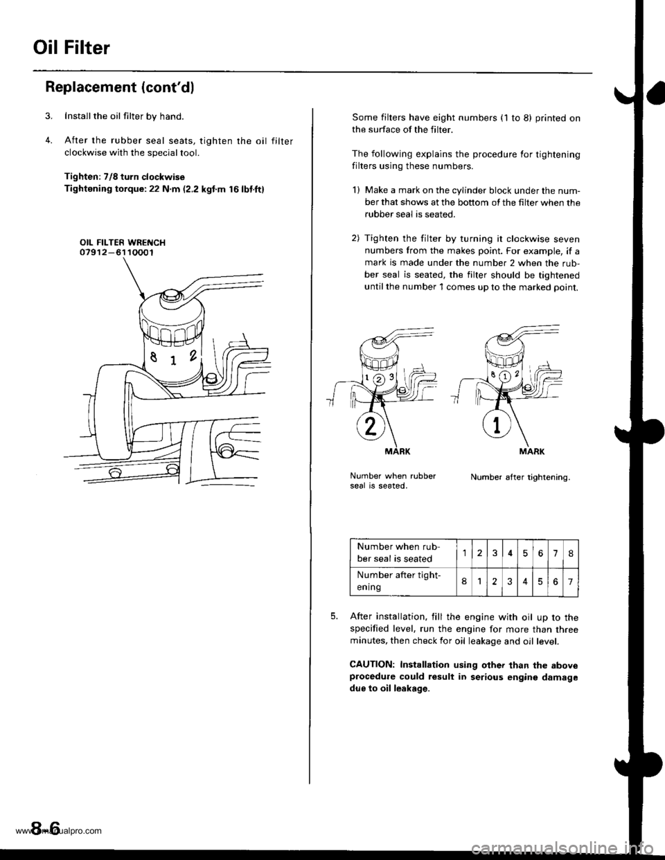
Oil Filter
Replacement (cont'd)
Installthe oil filter by hand.
After the rubber seal seats, tighten rhe oil filter
clockwise with the special tool.
Tighten: 7/8 turn clockwise
Tightening torque:22 N.m (2.2 kgt'm 16lbt.ft)
OIL FILTER WRENCH07912-61 10001
8-6
Some filters have eight numbers (1 to 8) printed on
the surface of the filter.
The following explains the procedure for tightening
filters using these numbers.
l) Make a mark on the cylinder block under the num-
ber that shows at the bottom of the filter when the
rubber seal is seated.
2) Tighten the filter by turning it clockwise seven
numbers from the makes point. For example, if a
mark is made under the number 2 when the rub-
ber seal is seated, the filter should be tightened
until the number 1 comes up to the marked point.
Number when rubberseal is seated.Number af ter tightening.
5.After installation. fill the engine with oil up to the
specified level, run the engine for more than threeminutes, then check for oil leakage and oil level.
GAUTION: Installation using other than the aboveprocedure could result in serious engine damage
due to oil leakage.
MARK
Number when rub-
ber seal is seated567IJ
Number after tight-
ening8123467
www.emanualpro.com
Page 982 of 1395
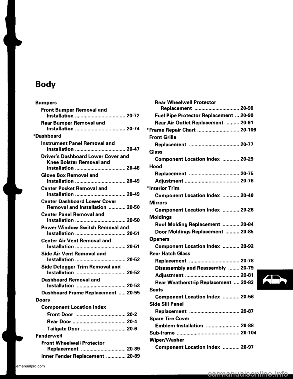
Body
Bumpers
Front Bumper Removal and
fnstaflation .........20-72
Rear Bumper Removal and
fnstaflation .........20-74
'Dashboard
lnstrument Panel Removal and
lnstallation .........20-47
Driver's Dashboard Lower Cover and
Knee Bolster Removal and
Installation .........20-48
Glove Box Removal and
lnstallation .........20-49
Center Pocket Removal and
lnstallation .........20-49
Center Dashboard Lower Cover
Removal and lnstallation ............ 20-50
Center Panel Removal and
lnstallation .........20-50
Power Window Switch Removal and
lnstallation .........20-51
Center Air Vent Removal and
lnstallation .........20-51
Side Air Vent Removal and
fnstallation .........20-52
Side Defogger Trim Removal and
fnstallation .........20-52
Dashboard Removal and
lnstallation .........20-53
Dashboard Frame Replacement ..... 20-55
Doors
Component Location Index
Front Door ,,...,,,,20-2
Rear Door ...........20-4
Tailgate Door ................................ 20-6
Fenderwell
Front Wheelwell Protector
Replacement .....20-89
Inner Fender Replacement .,.....,.,.... 20-89
Rear Wheelwell Protectol
Replacement .....20-90
Fuel Pipe Protector Replacement ... 20-90
Rear Air Outlet Replacement .......... 20-91
*Frame Repair Chart .............................. 20-106
Front Grille
Repf acement .........20-77
Glass
Component Location Index ............ 20-29
Hood
Replacement ......,,,20-75
Adjustment ............20-76
*lnterior Trim
Component Location Index ............ 20-40
Mirrors
Component Location Index .........,,, 20-26
Moldings
Roof Molding Replacement ............ 20-84
Door Moldings Replacement .......... 20-85
Openers
Component Location Index ............ 20-92
Rear Hatch Glass
Replacement .........20-74
Disassembly and Reassembly ........ 20-79
Adiustment ............20-81
Rear Weatherstrip Replacement .... 20-83
Seats
Component Location Index ............ 20-56
Side Sill Panel
Repfacement .........20-87
Spare Tire Cover
Emblem Installation ........................ 20-88
Sub-frame ..................20-104
Wiper/Washer
Component Location lndex ,,,,,....... 20-97
www.emanualpro.com
Page 1037 of 1395
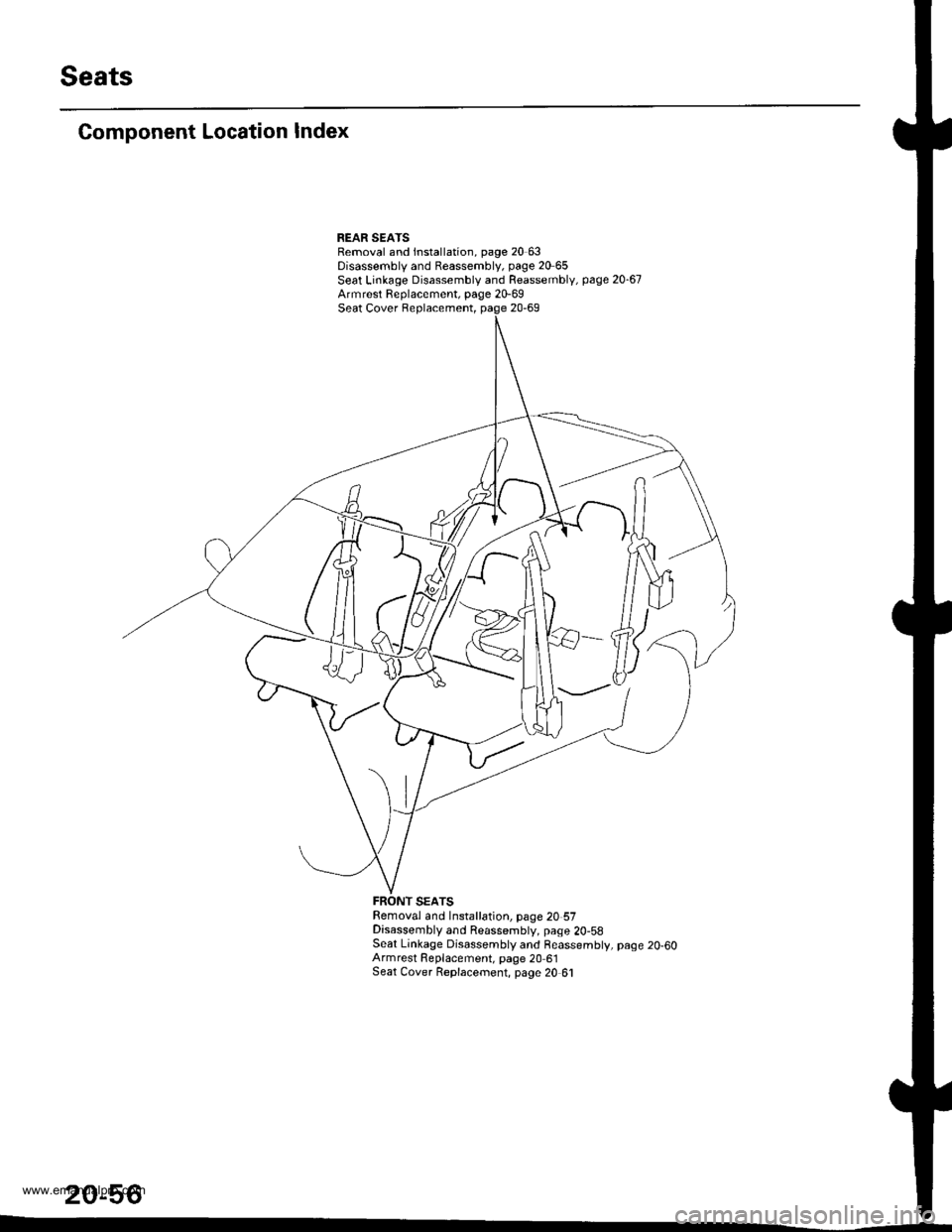
Seats
Component Location Index
REAR SEAISRemoval and lnstallation, page 20 63Disassembly and Reassembly, page 20 65Seat Linkage Disassembly and Reassembly, page 20-67Armrest Replacement, page 20-69Seat Cover Replacement, page 20-69
Removal and Installation, page 20 57Disassembly and Reassembly, page 2O-58Seat Linkage Disassembly and Reassembly, page 20-60Armrest Fleplacement, page 20 61Seat Cover Replacernent, page 20 61
20-56
www.emanualpro.com
Page 1039 of 1395
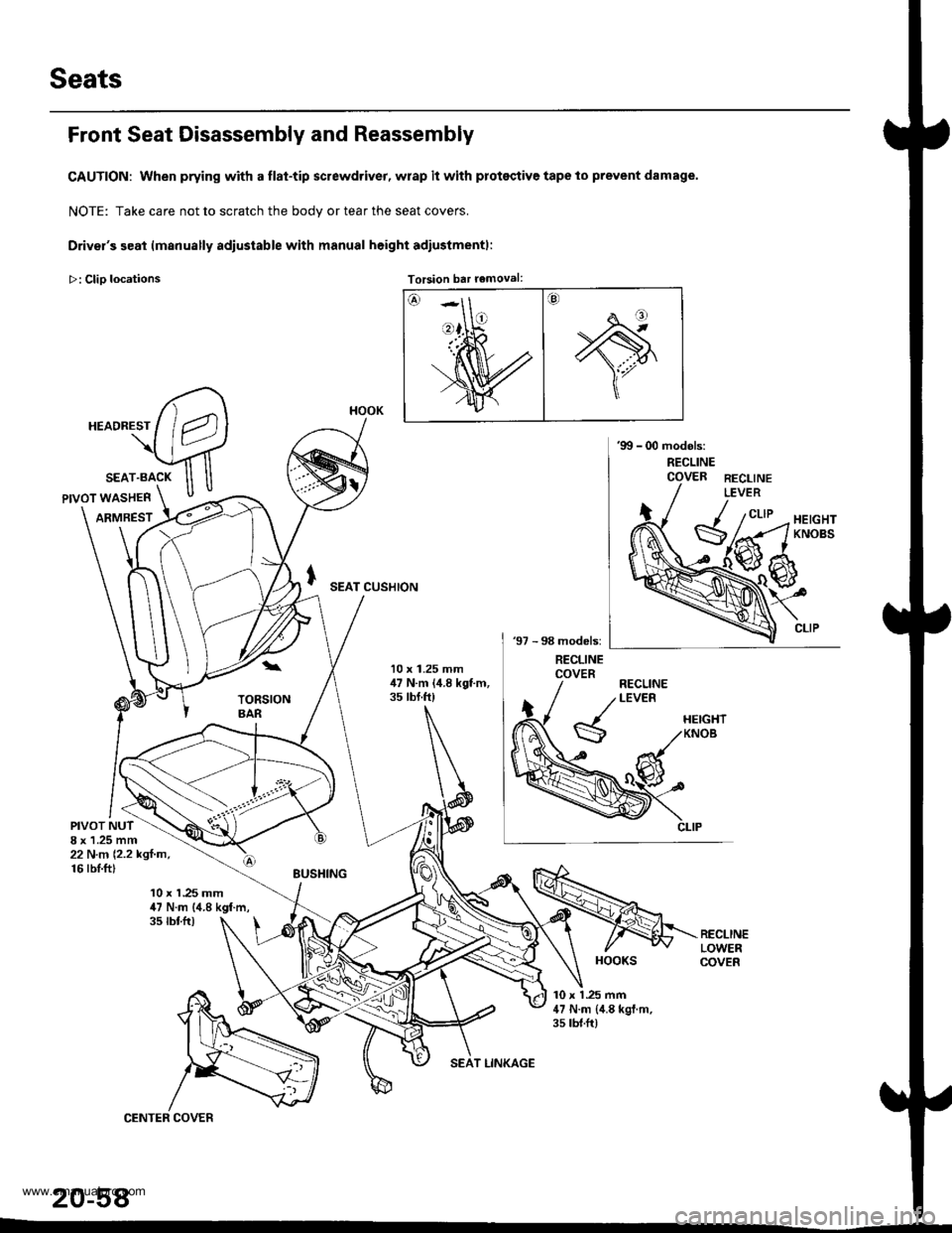
Seats
Front Seat Disassembly and Reassembly
CAUTION: When prying with a flat-tip screwdriver, wrap it with protsqtive tape to prevent damage.
NOTE: Take care not to scratch the bodv or tear the seat covers.
Driver's seat lmanually adiustable with manual height adiustmentl:
>: Clio locations Torsion bar removal:Torsion bar removal:
SEAT CUSHION
10 x 1.25 mm,17 N.m (,1.8 kgt m,35 tbt.ft)
PIVOT NUT8 x 1.25 mm22 N.n 12.2 kgl.m,16 rbI.ft)
10 x 1.25 mm47 N.m (4.8 kgf.m,35 tbtfr)
10 x 1 .25 mm47 N.m {,1.8 kgl.m.35 rbt.ft)
20-58
HOOK
HOOKS
www.emanualpro.com
Page 1041 of 1395
Seats
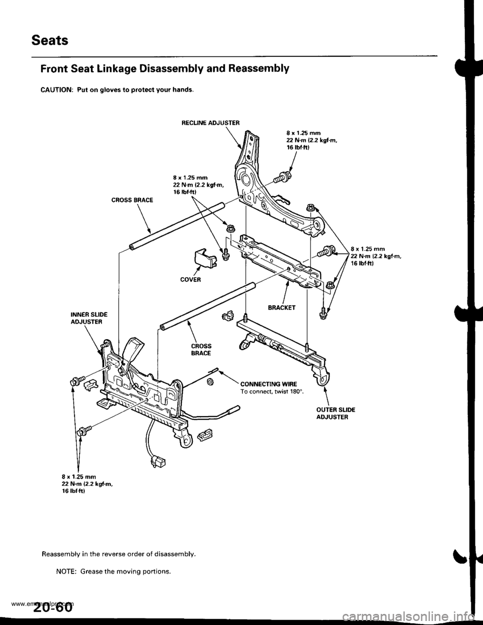
RECUNE ADJUSTER
Front Seat Linkage Disassembly and Reassembly
CAUTION: Put on gloves to protect your hands.
8 x 1 .25 mm22 N.m 12.2 kgl.m,16 tbf.fi)
8 x 1.25 mm22 N.m 12.2 kd-m,16 tbtf0
CROSS BRACE
8 x 1.25 mm22 N.m 12.2 kgl.m,16 tbf.f0
INNER SLIDEADJUSTER
8 x 1.25 mm22 N.rn l.2.2 kgl-m,16 rbr.ft)
CONNECTING WIRETo connect, twist 180".
cRossBRACE
OUTER SLIDEAOJUSTER
Reassembly in the reverse order of disassembly.
NOTE: Grease the moving portions.
20-60
www.emanualpro.com