engine HONDA ELEMENT 2010 1.G Manual PDF
[x] Cancel search | Manufacturer: HONDA, Model Year: 2010, Model line: ELEMENT, Model: HONDA ELEMENT 2010 1.GPages: 342, PDF Size: 5.76 MB
Page 311 of 342
Low Oil Pressure Indicator
This indicator should never
come on when the engine is
running. If it starts flashing or stays
on, the oil pressure has dropped very
low or lost pressure. Serious engine
damage is possible, and you should
take immediate action.
Running the engine with low oil
pressure can cause serious mechanical
damage almost immediately. Turn off
the engine as soon as you can safely get
the vehicle stopped. 1. Safely pull off the road, and shut
off the engine. Turn on the hazard
warning lights.
2. Let the vehicle sit for a minute. Open the hood, and check the oil
level (see page 201). An engine
very low on oil can lose pressure
during cornering and other drivingmaneuvers.
3. If necessary, add oil to bring the level back to the full mark on the
dipstick (see page 251).
4. Start the engine, and watch the oil pressure indicator. If it does not go
out within 10 seconds, turn off the
engine. There is a mechanical
problem that needs to be repaired
before you can continue driving(see Emergency Towing on page
303). Charging System Indicator
If the charging system
indicator comes on brightly
when the engine is running, the
battery is not being charged.
Immediately turn off all electrical
accessories. Try not to use other
electrically operated controls such as
the power windows. Keep the engine
running; starting the engine will
discharge the battery rapidly.
Go to a service station or garage
where you can get technicalassistance.
Low Oil Pressure Indicator, Charging System Indicator
295
Taking Care of the Unexpected
Table of Contents
Page 312 of 342
If this indicator comes on
while driving, it means one
of the engine's emissions control
systems may have a problem. Even
though you may feel no difference in
your vehicle's performance, it can
reduce your fuel economy and cause
increased emissions. Continued
operation may cause serious damage.
If you have recently refueled your
vehicle, the indicator coming on
could be due to a loose or missing
fuel fill cap. You will also see a ‘‘ CHECK FUEL CAP ’’message on
the information display. Tighten the
cap until it clicks at least once.
Tightening the cap will not turn the
indicator off immediately; it can take
several days of normal driving. If the indicator comes on repeatedly,
even though it may turn off as you
continue driving, have your vehicle
checked by your dealer as soon as possible.
If you keep driving with the malfunction
indicator lamp on, you can damage
your vehicle's emissions controls and
engine. Those repairs may not be
covered by your vehicle's warranties.
If your vehicle has an automatic
transmission, the malfunction
indicator lamp may also come on
with the
‘‘D ’’indicator. Readiness Codes
Your vehicle has certain
‘‘readiness
codes ’’that are part of the on-board
diagnostics for the emissions
systems. In some states, part of the
emissions testing is to make sure
these codes are set. If they are not
set, the test cannot be completed.
If the battery in your vehicle has been
disconnected or gone dead, these
codes may be erased. It can take
several days of driving under various
conditions to set the codes again.
To check if they are set, turn the
ignition switch to the ON (II)
position, without starting the engine.
The malfunction indicator lamp will
come on for 20 seconds. If it then
goes off, the readiness codes are set.
If it blinks five times, the readiness
codes are not set. If possible, do not
take your vehicle for an emissions
test until the readiness codes are set.
Refer to Emissions Testing for more
information (see page 319).
Malfunction Indicator Lamp
296
Table of Contents
Page 314 of 342
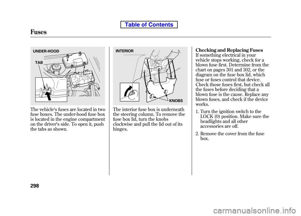
The vehicle's fuses are located in two
fuse boxes. The under-hood fuse box
is located in the engine compartment
on the driver's side. To open it, push
the tabs as shown.The interior fuse box is underneath
the steering column. To remove the
fuse box lid, turn the knobs
clockwise and pull the lid out of itshinges.Checking and Replacing Fuses
If something electrical in your
vehicle stops working, check for a
blown fuse first. Determine from the
chart on pages 301 and 302, or the
diagram on the fuse box lid, which
fuse or fuses control that device.
Check those fuses first, but check all
the fuses before deciding that a
blown fuse is the cause. Replace any
blown fuses, and check if the deviceworks.
1. Turn the ignition switch to the
LOCK (0) position. Make sure the
headlights and all other
accessories are off.
2. Remove the cover from the fuse box.
UNDER-HOOD
TABINTERIOR
KNOBS
Fuses
298
Table of Contents
Page 322 of 342
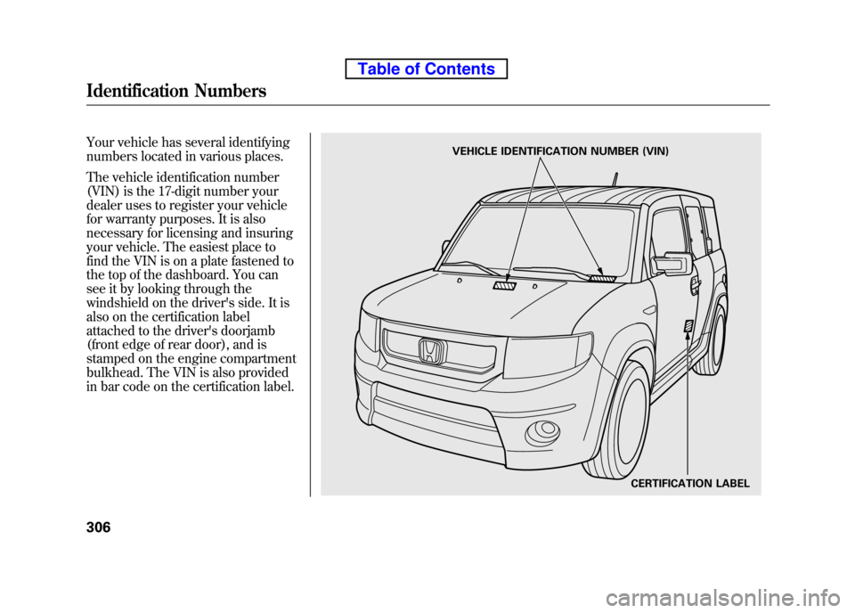
Your vehicle has several identifying
numbers located in various places.
The vehicle identification number
(VIN) is the 17-digit number your
dealer uses to register your vehicle
for warranty purposes. It is also
necessary for licensing and insuring
your vehicle. The easiest place to
find the VIN is on a plate fastened to
the top of the dashboard. You can
see it by looking through the
windshield on the driver's side. It is
also on the certification label
attached to the driver's doorjamb
(front edge of rear door), and is
stamped on the engine compartment
bulkhead. The VIN is also provided
in bar code on the certification label.VEHICLE IDENTIFICATION NUMBER (VIN)CERTIFICATION LABEL
Identification Numbers
306
Table of Contents
Page 323 of 342
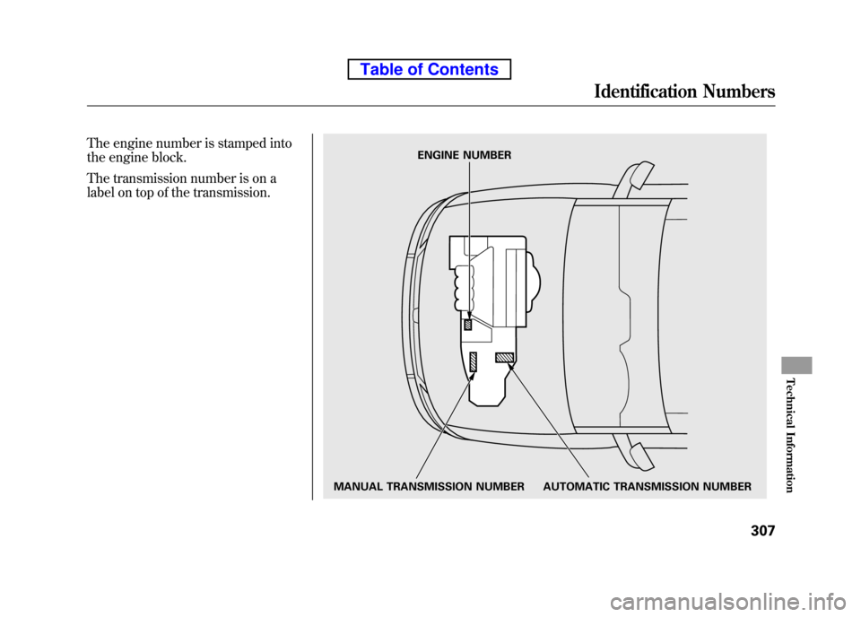
The engine number is stamped into
the engine block.
The transmission number is on a
label on top of the transmission.
MANUAL TRANSMISSION NUMBER AUTOMATIC TRANSMISSION NUMBERENGINE NUMBER
Identification Numbers
307
Technical Information
Table of Contents
Page 324 of 342

DimensionsLength 169.9 in (4,316 mm)ꭧ 1ꭧ 2
170.4 in (4,328 mm)ꭧ 3
Width 71.6 in (1,819 mm)
Height 70.4 in (1,788 mm)ꭧ1,ꭧ 2
69.6 in (1,768 mm)ꭧ3
Wheelbase 101.4 in (2,575 mm)
Track Front 62.1 in (1,577 mm)ꭧ1,ꭧ 2
62.1 in (1,578 mm)ꭧ3
Rear 62.3 in (1,582 mm)ꭧ1,ꭧ 2
62.5 in (1,587 mm)ꭧ3
Weights
Gross vehicle weight rating See the certification label attached to the driver's doorjamb
(front edge of rear door). Seating Capacities
Total 4
Front 2
Rear 2
Engine Type Water cooled 4-stroke DOHC i-VTEC 4-cylinder gasoline engine
Bore x Stroke 3.43 x 3.90 in (87.0 x 99.0 mm)
Displacement 144 cu-in (2,354 cm
3)
Compression ratio 9.7 : 1
Spark plugs NGK: IZFR6K-11 DENSO: SKJ20DR-M11
ꭧ 1: LX model
ꭧ 2: EX model
ꭧ 3: SC model
Specifications
308
Table of Contents
Page 325 of 342

CapacitiesFuel tank Approx.
15.9 US gal (60 L)
Engine oil Change
ꭧ 1
Including filter 4.4 US qt (4.2 L)
Without filter 4.2 US qt (4.0 L)
Total 5.6 US qt (5.3 L) Capacities
Engine coolant AutomaticTransmission
Change
ꭧ21.35 US gal (5.1 L)
Total 1.90 US gal (7.2 L)
ManualTransmission Change
ꭧ21.37 US gal (5.2 L)
Total 1.93 US gal (7.3 L)
Automatictransmission fluid Change
4WD 2.6 US qt (2.5 L)
2WD 2.7 US qt (2.6 L)
Total 4WD 7.6 US qt (7.2 L)
2WD 7.4 US qt (7.0 L)
Manual transmission fluid Change 2.0 US qt (1.9 L) Total
4WD 2.4 US qt (2.3 L)
2WD 2.3 US qt (2.2 L)
Rear differential
fluid (4WD) Change 1.1 US qt (1.0 L)
Total 1.3 US qt (1.2 L)
Windshield washer reservoir 4.8 US qt (4.5 L)
ꭧ 1: Excluding the oil remaining in the engine
ꭧ 2: Including the coolant in the reserve tank and that remaining in the engine
Reserve tank capacity:
0.15 US gal (0.55 L)
Specifications
309
Technical Information
Table of Contents
Page 332 of 342

The burning of gasoline in your
vehicle's engine produces several by-
products. Some of these are carbon
monoxide (CO), oxides of nitrogen
(NOx), and hydrocarbons (HC).
Gasoline evaporating from the tank
also produces hydrocarbons.
Controlling the production of NOx,
CO, and HC is important to the
environment. Under certain
conditions of sunlight and climate,
NOx and HC react to form photochemical‘‘smog. ’’Carbon
monoxide does not contribute to
smog creation, but it is a poisonousgas. The Clean Air Act
The United States Clean Air Actꭧsets
standards for automobile emissions. It
also requires that automobile
manufacturers explain to owners how
their emissions controls work and
what to do to maintain them. This
section summarizes how the
emissions controls work.
ꭧIn Canada, Honda vehicles comply
with the Canadian emission
requirements, as specified in an
agreement with Environment Canada,
at the time they are manufactured.
Crankcase Emissions Control System
Your vehicle has a positive crankcase
ventilation system. This keeps gasses
that build up in the engine's crankcase
from going into the atmosphere. The
positive crankcase ventilation valve
routes them from the crankcase back
to the intake manifold. They are then
drawn into the engine and burned. Evaporative Emissions Control System
As gasoline evaporates in the fuel
tank, an evaporative emissions
control canister filled with charcoal
adsorbs the vapor. It is stored in this
canister while the engine is off. After
the engine is started and warmed up,
the vapor is drawn into the engine
and burned during driving.
Onboard Refueling Vapor Recovery
The onboard refueling vapor
recovery (ORVR) system captures
the fuel vapors during refueling. The
vapors are adsorbed in a canister
filled with activated carbon. While
driving, the fuel vapors are drawn
into the engine and burned off.
Emissions Controls
316
Table of Contents
Page 333 of 342

Exhaust Emissions Controls
The exhaust emissions controls
include three systems: PGM-FI,
ignition timing control, and three
way catalytic converter. These three
systems work together to control the
engine's combustion and minimize
the amount of HC, CO, and NOx that
comes out the tailpipe. The exhaust
emissions control systems are
separate from the crankcase and
evaporative emissions control systems.PGM-FI System
The PGM-FI system uses sequential
multiport fuel injection. It has three
subsystems: air intake, engine
control, and fuel control. The
powertrain control module (PCM) in
automatic transmission vehicles or
the engine control module (ECM) in
manual transmission vehicles uses
various sensors to determine how
much air is going into the engine. It
then controls how much fuel to inject
under all operating conditions.
Ignition Timing Control System
This system constantly adjusts the
ignition timing, reducing the amount
of HC, CO, and NOx produced.
Three Way Catalytic Converter
The three way catalytic converter is
in the exhaust system. Through
chemical reactions, it converts HC,
CO, and NOx in the engine's exhaust
to carbon dioxide (CO2), nitrogen
(N 2), and water vapor. Replacement Parts
The emissions control systems are
designed and certified to work
together in reducing emissions to
levels that comply with the Clean Air
Act. To make sure the emissions
remain low, you should use only new
Honda replacement parts or their
equivalent for repairs. Using lower
quality parts may increase the
emissions from your vehicle.
The emissions control systems are
covered by warranties separate from
the rest of your vehicle. Read your
warranty manual for moreinformation.
Emissions Controls
317
Technical Information
Table of Contents
Page 334 of 342
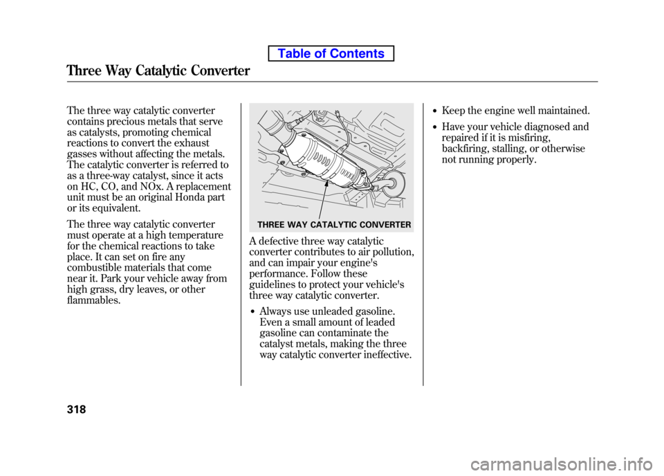
The three way catalytic converter
contains precious metals that serve
as catalysts, promoting chemical
reactions to convert the exhaust
gasses without affecting the metals.
The catalytic converter is referred to
as a three-way catalyst, since it acts
on HC, CO, and NOx. A replacement
unit must be an original Honda part
or its equivalent.
The three way catalytic converter
must operate at a high temperature
for the chemical reactions to take
place. It can set on fire any
combustible materials that come
near it. Park your vehicle away from
high grass, dry leaves, or otherflammables.
A defective three way catalytic
converter contributes to air pollution,
and can impair your engine's
performance. Follow these
guidelines to protect your vehicle's
three way catalytic converter.● Always use unleaded gasoline.
Even a small amount of leaded
gasoline can contaminate the
catalyst metals, making the three
way catalytic converter ineffective. ●
Keep the engine well maintained.
● Have your vehicle diagnosed and
repaired if it is misfiring,
backfiring, stalling, or otherwise
not running properly.
THREE WAY CATALYTIC CONVERTER
Three Way Catalytic Converter
318
Table of Contents