battery HONDA FIT 2017 3.G Quick Guide
[x] Cancel search | Manufacturer: HONDA, Model Year: 2017, Model line: FIT, Model: HONDA FIT 2017 3.GPages: 76, PDF Size: 8.56 MB
Page 4 of 76
| 1
V
ISUAL INDEX
Quickly locate items in the vehicle’s interior.
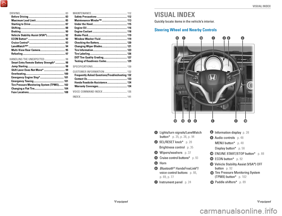
Steering Wheel and Nearby Controls
1 Lights/turn signals/LaneWatch
button* p. 35, p. 36, p. 94
2 SEL/RESET knob* p. 28
Brightness control p. 35
3 Wipers/washers p. 37
4 Cruise control buttons* p. 93
5 Horn
6 Bluetooth® HandsFreeLink®/
voice control buttons p. 66,
p. 69, p. 77
7 Instrument panel p. 24
8 Information display p. 28
9 Audio controls p. 48
MENU button* p. 48
Display button* p. 56
10 ENGINE START/STOP button* p. 88
11 ECON button* p. 92
12 Vehicle Stability Assist (VSA®) OFF
button p. 92
Tire Pressure Monitoring System
(TPMS) button* p. 102
Paddle shifters* p. 89
VISUAL INDEX
*if equipped
*if equipped
7
125641013
14111283
13
14
9
DRIVING....................................................................... 83
Before Driving ......................................................... 83
Maximum Load Limit .............................................. 85
Starting to Drive ...................................................... 87
Shifting ...................................................................... 88
Braking ..................................................................... 90
Vehicle Stability Assist (VSA®) ............................ 92
ECON Button* .......................................................... 92
Cruise Control* ........................................................ 93
LaneWatch™* ......................................................... 94
Multi-View Rear Camera.......................................
95
Refueling
.................................................................. 97
HANDLING THE UNEXPECTED
................................ 98
Smart Entry Remote Battery Strength* ............... 98
Jump Starting .......................................................... 98
Shift Lever Does Not Move* ................................. 99
Overheating ............................................................ 100
Emergency Engine Stop* ..................................... 101
Emergency Towing ............................................... 101
Tire Pressure Monitoring System (TPMS)........
102
Changing a Flat Tire.............................................. 104
Fuse Locations
....................................................... 108MAINTENANCE
........................................................
112
Safety Precautions ............................................... 112
Maintenance Minder™ ....................................... 113
Under the Hood ...................................................... 115
Engine Oil ............................................................... 116
Engine Coolant ...................................................... 118
Brake Fluid ............................................................. 119
Window Washer Fluid ......................................... 119
Checking the Battery ............................................ 120
Changing Wiper Blades ....................................... 121
Tire Information ..................................................... 123
Tire Labeling .......................................................... 126
DOT Tire Quality Grading
..................................... 127
Testing of Readiness Codes
................................ 129
SPECIFICATIONS
...................................................... 130
CUSTOMER INFORMATION
................................... 132
Frequently Asked Questions/Troubleshooting 132
Contact Us .............................................................. 133
Honda Roadside Assistance ............................... 134
Warranty Coverages ............................................. 134
VOICE COMMAND INDEX
...................................... 135
INDEX
........................................................................\
. 141
Page 16 of 76
24 || 25
I
NSTRUMENT PANELINSTRUMENT PANEL
Smart Entry system*
There is a problem with the smart entry system.
Malfunction indicator lamp (check engine light)
• The emissions control system may have a problem, or the fuel cap is\
loose
or missing.
• (Blinks) A
misfire in the engine’s cylinders is detected. Stop in a safe place,
and wait for the engine to cool down.
Anti-lock Brake System (ABS)
There is a problem with the anti-lock brake system. Y
our vehicle still has
normal braking ability, but no anti-lock function.
Tire Pressure Monitoring System (TPMS) (U.S. models only)
There is a problem with the tire pressure monitoring system, or the vehi\
cle is
fitted with the compact spare tire.
Vehicle Stability Assist (VSA
®)
There is a problem with the VSA system or hill start assist system.
Brake system
There is a problem with a braking system other than the regular brakes.
Electric power steering
There is a problem with the system. Stop in a safe place, and restart th\
e
vehicle.
Starter system*
There is a problem with the starter system.
High temperature
The engine coolant temperature is high. Drive slowly to prevent overheat\
ing.
If the indicator remains on, immediately stop the vehicle in a safe plac\
e (see
page 100).
Low temperature
The engine coolant temperature is low. If the indicator remains on, there
may be a problem with temperature sensors.
Canada U.S.
U.S.
Canada
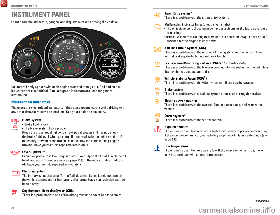
Learn about the indicators, gauges, and displays related to driving the \
vehicle.
Indicators briefly appear with each engine start and then go out. Red \
and amber
indicators are most critical. Blue and green indicators are used for gen\
eral
information.
Malfunction Indicators
These are the most critical indicators. If they come on and stay lit whi\
le driving or at
any other time, there may be a problem. See your dealer if necessary.
Brake system
• Brake fluid is low.
• The brake system has a problem.
Press the brake pedal lightly to check pedal pressure. If normal, check \
the brake fluid level when you stop. If abnormal, take immediate actio\
n. If
necessary, downshift the transmission to slow the vehicle using engine
braking. Have your vehicle repaired immediately.
Low oil pressure
Engine oil pressure is low. Stop in a safe place. Open the hood. Check the oil
level, and add oil if necessary (see page 117). If the indicator does \
not turn
off, have your vehicle repaired immediately.
Charging system
The battery is not charging. Turn off all electrical items, but do not turn off
the vehicle to prevent further battery discharge. Have your vehicle repa\
ired
immediately.
Supplemental Restraint System (SRS)
There is a problem with one of the airbag systems or seat belt tensioner\
s.
Canada
U.S.
INSTRUMENT PANEL
*if equipped
Page 47 of 76
86 || 87
DRIVING
DRIVING
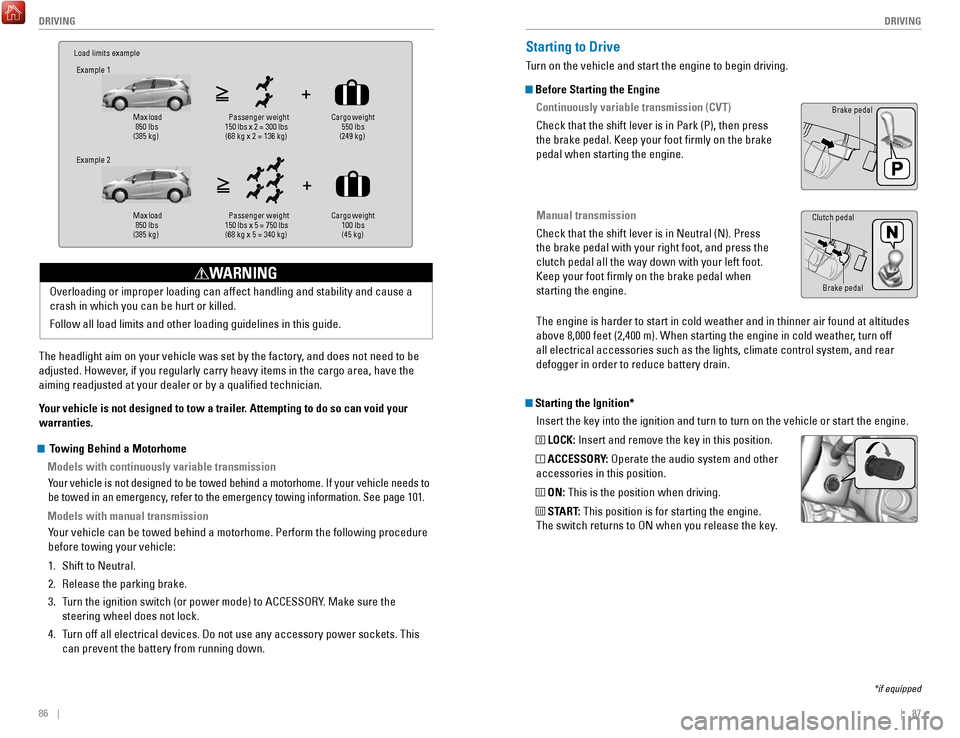
Load limits example
Example 1
Max load
850 lbs
(385 kg) Pass
enger weight
150 lbs x 2 = 300 lbs (68 kg x 2 = 136 kg) Cargo weight
550 lbs
(249 kg)
Example 2
Max load
850 lbs
(385 kg) Pa
ssenger w eight
150 lbs x 5 = 750 lbs (68 kg x 5 = 340 kg) Cargo weight
100 lbs
(45 kg)
The headlight aim on your vehicle was set by the factory, and does not need to be
adjusted. However, if you regularly carry heavy items in the cargo area, have the
aiming readjusted at your dealer or by a qualified technician.
Your vehicle is not designed to tow a trailer. Attempting to do so can void your
warranties. Overloading or improper loading can affect handling and stability and ca\
use a
crash in which you can be hurt or killed.
Follow all load limits and other loading guidelines in this guide.
WARNING
Starting the Ignition*
Insert the key into the ignition and turn to turn on the vehicle or star\
t the engine.
0 LOCK: Insert and remove the key in this position.
I ACCESSORY: Operate the audio system and other
accessories in this position.
II ON: This is the position when driving.
III START: This position is for starting the engine.
The switch returns to ON when you release the key.
Starting to Drive
Turn on the vehicle and start the engine to begin driving.
Before Starting the Engine
Continuously variable transmission (CVT)
Check that the shift lever is in Park (P), then press
the brake pedal. Keep your foot firmly on the brake
pedal when starting the engine.
Manual transmission
Check that the shift lever is in Neutral (N). Press
the brake pedal with your right foot, and press the
clutch pedal all the way down with your left foot.
Keep your foot firmly on the brake pedal when
starting the engine.
Brake pedal
The engine is harder to start in cold weather and in thinner air found a\
t altitudes
above 8,000 feet (2,400 m). When starting the engine in cold weather, turn off
all electrical accessories such as the lights, climate control system, a\
nd rear
defogger in order to reduce battery drain.
*if equipped
Brake pedal
Clutch pedal
Towing Behind a Motorhome
Models with continuously variable transmission
Your vehicle is not designed to be towed behind a motorhome. If your vehi\
cle needs to
be towed in an emergency, refer to the emergency towing information. See page 101.
Models with manual transmissionYour vehicle can be towed behind a motorhome. Perform the following proce\
dure
before towing your vehicle:
1.
Shift to Neutral.
2.
Release the parking brake.
3.
Turn the ignition switch (or power mode) to ACCESSORY. Make sure the
steering wheel does not lock.
4.
Turn off all electrical devices. Do not use any accessory power sockets. This
can prevent the battery from running down.
Page 53 of 76
98 || 99
HANDLING THE UNEXPECTED
HANDLING THE UNEXPECTED
Learn about what to do in critical or emergency situations.
Smart Entry Remote Battery Strength*
If the battery life in your remote transmitter is weak, follow the below\
steps to start
the engine.
1.
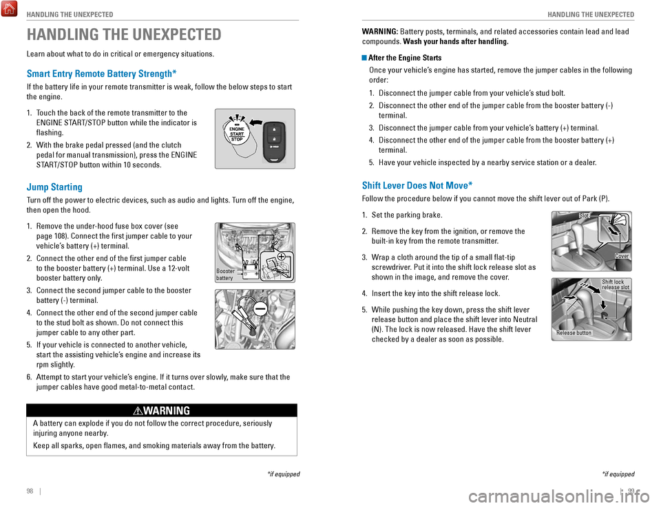
Touch the back of the remote transmitter to the
ENGINE START/STOP button while the indicator is
flashing.
2.
With the brake pedal pressed (and the clutch
pedal for manual transmission), press the ENGINE
START/STOP button within 10 seconds.
Jump Starting
Turn off the power to electric devices, such as audio and lights. Turn off the engine,
then open the hood.
1.
Remove the under-hood fuse box cover (see
page 108). Connect the first jumper cable to your
vehicle’s battery (+) terminal.
2.
Connect the other end of the first jumper cable
to the booster battery (+) terminal. Use a 12-volt
booster battery only.
3.
Connect the second jumper cable to the booster
battery (-) terminal.
4.
Connect the other end of the second jumper cable
to the stud bolt as shown. Do not connect this
jumper cable to any other part.
5.
If your vehicle is connected to another vehicle,
start the assisting vehicle’s engine and increase its
rpm slightly.
6.
Attempt to start your vehicle’s engine. If it turns over slowly, make sure that the
jumper cables have good metal-to-metal contact.
HANDLING THE UNEXPECTED
*if equipped
A battery can explode if you do not follow the correct procedure, seriou\
sly
injuring anyone nearby.
Keep all sparks, open flames, and smoking materials away from the batt\
ery.
WARNING
Booster
battery
WARNING: Battery posts, terminals, and related accessories contain lead and lead\
compounds. Wash your hands after handling.
After the Engine Starts Once your vehicle’s engine has started, remove the jumper cables in the following
order:
1.
Disconnect the jumper cable from your vehicle’s stud bolt.
2.
Disconnect the other end of the jumper cable from the booster battery (\
-)
terminal.
3.
Disconnect the jumper cable from your vehicle’s battery (+) terminal.
4.
Disconnect the other end of the jumper cable from the booster battery (\
+)
terminal.
5.
Have your vehicle inspected by a nearby service station or a dealer.
Shift Lever Does Not Move*
Follow the procedure below if you cannot move the shift lever out of Par\
k (P).
1.
Set the parking brake.
2.
Remove the key from the ignition, or remove the
built-in key from the remote transmitter.
3.
Wrap a cloth around the tip of a small flat-tip
screwdriver. Put it into the shift lock release slot as
shown in the image, and remove the cover
.
4.
Insert the key into the shift release lock.
5.
While pushing the key down, press the shift lever
release button and place the shift lever into Neutral
(N). The lock is now released. Have the shift lever
checked by a dealer as soon as possible.
*if equipped
Slot
Release button Shift lock
release slot
Cover
Page 58 of 76
108 || 109
HANDLING THE UNEXPECTED
HANDLING THE UNEXPECTED
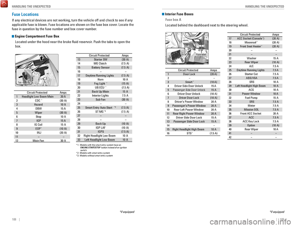
Fuse Locations
If any electrical devices are not working, turn the vehicle off and chec\
k to see if any
applicable fuse is blown. Fuse locations are shown on the fuse box cover\
. Locate the
fuse in question by the fuse number and box cover number.
Engine Compartment Fuse Box
Located under the hood near the brake fluid reservoir. Push the tabs to open the
box.
Circuit Protecte dAmps
2
1Headlight Low Beam Main 20 A
CDC*(30 A)
3
Hazard10 A
4
DBW15 A
5
Wiper(30 A)
6
Stop10 A
7
IG P15 A
8
IG Coi l15A
9
EOP*(10 A)
10 INJ
(20 A)
11
––
12Main Fan30 A 13
Starter SW(30 A)
14
MG Clutch(7.5 A)
15
Battery Senso r(7.5A )
16
––
17 Daytime Running Lights (7.5 A)
18
Horn10 A
19
(15 A)
20Fog Light*
*1 :M odels with the smart entry system have an
*
* ENGINE START/STO
P button instead of an ignition
switch .
2: Mo dels with smart entry system
3:Mo dels without smart entry system
Amps
21Back Up Main
Circuit Protecte d
15A
22
7.5 A
Interior Lights
23
Sub Fa n
24 (3
0A )––
26
25 Smart Entry Auto Start*2(7.5 A)
ST MG*3(7.5A)
27
––
28––
29Back Up(1 0A )
30
IGP LAF(1 0A )
31
IGPS(7.5 A)
32 Right Headlight Low Beam 10A
33 Left Headlight Low Beam 10A
UB ECU
*(7.5 A)
*if equipped
Ta b
Circuit Protecte
dAmps1Door Lock(20 A)2––3Smart*(10 A)4Driver Side Door Unlock15 A5Passenger Side Door Unlock15 A6Driver Door Unlock(10 A)7Driver Door Lock(10 A)8Driver’s Power Window20A9Passenger’s Power Window20A10Rear Left Power Window20A11Rear Right Power Window20A12Driver Side Door Lock15A13Passenger Side Door Lock15A14––15Right Headlight High Beam10A16STS*(7.5A )
17 ACC Socket (Console*) (20 A)
18 Moonroof*(20 A)
19 Front Seat Heater*(20 A)
20 – –
Circuit Protected Amps
21 – –
22 Washer 15A
23 Rear Wiper (10A )
24 A/C 7.5A
25 Daytime Running Lights 7.5 A
26 Starter Cut 7.5A
27 ABS/VSA 7.5 A
28 SRS 10A
29 Left Headlight High Beam 10A
30 ACG 10A
31 Power Window 10 A
32 Fuel Pump 15A
33 SRS 7.5A
34 Meter 7.5A
35 Mission SOL 7.5A
36 Front ACC Socket 20A
37 ACC 7.5A
38 ACC Key Lock 7.5A
39 Option (10A )
40 Rear Wiper 10 A
41 � �
42 � �
Interior Fuse Boxes
Fuse box A
Located behind the dashboard next to the steering wheel.
*if equipped
Fuse label
Circuit Protecte dAmps
1 Door Lock (20 A)
2 – –
3 Smart
*(10 A)
4 Driver Side Door Unlock 15 A
5
Passenger Side Door Unlock15 A
6 Driver Door Unlock (10 A)
7 Driver Door Lock (10 A)
8 Driver’s Power Window 20A
9 Passenger’s Power Window 20A
10 Rear Left Power Window 20A
11 Rear Right Power Window 20A
12 Driver Side Door Lock 15A
13 Passenger Side Door Lock 15A
14 – –
15 Right Headlight High Beam 10A
16 STS
*(7.5A )
17ACC Socket (Console*)(20 A)18Moonroof*(20 A)19Front Seat Heater*(20 A)20––
Circuit Protecte dAmps
21––22Washer15A23Rear Wiper(10A )24A/C7.5A25Daytime Running Lights7.5 A26Starter Cut7.5A27ABS/VSA7.5 A28SRS10A29Left Headlight High Beam10A30ACG10A31Power Window10 A32Fuel Pump15 A33SRS7.5A34Meter7.5A35Mission SOL7.5A36Front ACC Socket20A37ACC7.5A38ACC Key Lock7.5A39Option(10A )40Rear Wiper10 A41��42��
Page 59 of 76
110 || 111
HANDLING THE UNEXPECTED
HANDLING THE UNEXPECTED
Circuit ProtectedAmps
1
EPS70 A
IG Main30 A*1
50A*2
Fuse Box Main 250 AABS/VSA Motor40 AFuse Box Main 130AFuse Box Main 340A
2––
––
––
––
––
––
*1:M odels with smart entry system*2:M odels without smart entry system
3Heater30A4*1IG Main 230A
4*2––5ABS/VSA FSR30 A
7––
8–
9Small Light10 A
10 ACC Socket (Console)*(2 0A )11Rear Defogger30A
12*1��12*2ACC Key Lock (7.5 A)13Heated Door Mirror*(1 0A )
14 A/C Blower SW (7.5 A)
15*1––15*2Wiper30A
6��
(7.5 A)*
Fuse box B
Located behind the dashboard next to the steering wheel. Remove the cove\
r by
putting a flat-tip screwdriver into the side slot as shown.
*if equipped
Cover
Inspecting and Changing Fuses
1.
Turn the vehicle off, including all lights and
accessories.
2.
Check the fuses on the battery in the engine
compartment. If the fuse is blown, have it
replaced by a dealer.
3.
Remove the fuse box cover.
4.
Inspect the small fuses in the engine
compartment and the vehicle interior.
If there is a burned-out fuse, remove it with the
fuse puller and replace it with a new one.
5.
Check the large fuse in the engine compartment.
If the fuse is blown, use a Phillips-head
screwdriver to remove the screw and replace the
fuse with a new one. Reinstall the screw.
Replacing a fuse with one that has a higher rating greatly increases the\
chances
of damaging the electrical system.
NOTICE
Blown
Fuse box on battery
Fuse puller
Combined fuse
Blown fuse
Page 60 of 76
112 || 113
MAINTENANCE
MAINTENANCE
Safety Precautions
Some of the most important safety precautions are listed below; however, we cannot
warn you of every conceivable hazard that can arise in performing mainte\
nance.
Only you can decide whether or not you should perform a given task.
Maintenance Safety
•
To reduce the possibility of fire or explosion, keep cigarettes, sparks\
, and flames
away from the battery and all fuel-related parts.
•
Never leave rags, towels, or other flammable objects under the hood. H\
eat from
the engine and exhaust can ignite them, causing a fire.
•
To clean parts, use a commercially available degreaser or parts cleaner, not
gasoline.
•
Wear eye protection and protective clothing when working with the battery\
or
compressed air.
•
Do not run the engine in confined spaces where carbon monoxide gas can\
accumulate.
Vehicle Safety
•
The vehicle must be stationary, and parked on level ground with the parking
brake set and the engine off.
•
Be aware that hot parts can burn you.
•
Be aware that moving parts can injure you.
Improperly maintaining this vehicle or failing to correct a problem befo\
re
driving can cause a crash in which you can be seriously hurt or killed. \
Always follow the inspection and maintenance recommendations according
to the schedules in this guide.
WARNING
Failure to properly follow maintenance instructions and precautions can \
cause you to be seriously hurt or killed.
Always follow the procedures and precautions in this guide.
WARNING
Learn about basic maintenance that you can perform on the vehicle yourse\
lf, as well
as information about how to best maintain the vehicle.
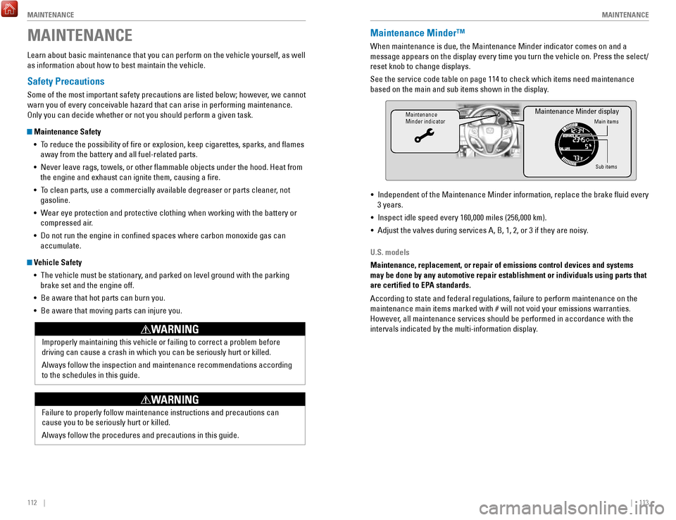
MAINTENANCEMaintenance Minder™
When maintenance is due, the Maintenance Minder indicator comes on and a\
message appears on the display every time you turn the vehicle on. Press\
the select/
reset knob to change displays.
See the service code table on page 114 to check which items need mainten\
ance
based on the main and sub items shown in the display.
Maintenance
Minder indicatorMain items
Sub items
Maintenance Minder display
• Independent of the Maintenance Minder information, replace the brake fl\
uid every
3 years.
•
Inspect idle speed every 160,000 miles (256,000 km).
•
Adjust the valves during services A, B, 1, 2, or 3 if they are noisy.
U.S. models
Maintenance, replacement, or repair of emissions control devices and sys\
tems
may be done by any automotive repair establishment or individuals using \
parts that
are certified to EPA standards.
According to state and federal regulations, failure to perform maintenan\
ce on the
maintenance main items marked with # will not void your emissions war
ranties.
However, all maintenance services should be performed in accordance with the
intervals indicated by the multi-information display.
Page 61 of 76
114 || 115
MAINTENANCE
MAINTENANCE
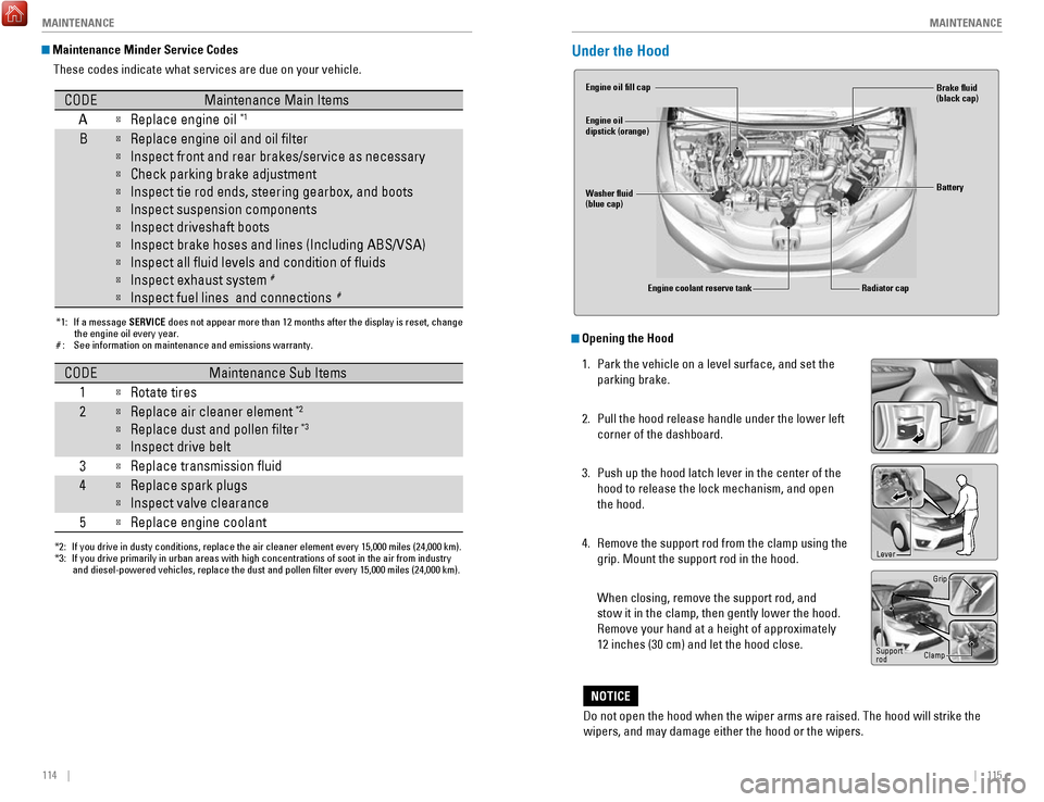
Maintenance Minder Service Codes
These codes indicate what services are due on your vehicle.
*1: If a message SERVICE does not appear more than 12 months after the display is reset, changethe engine oil every year.
#: See information on maintenance and emissions warranty.
CODEMaintenance Main Items
A
�Replace engine oi l*1
B�Replace engine oil and oil �lter
�Inspect front and rear brakes/service as necessary
�Check parking brake adjustment
�Inspect tie rod ends, steering gearbox, and boots
�Inspect suspension component s
�Inspect driveshaft boots
�Inspect brake hoses and lines (Including ABS/VSA)
�Inspect all �uid levels and condition of �uids
�Inspect exhaust system#
�Inspect fuel lines and connections#
*2:If you drive in dusty conditions, replace the air cleaner element every \
15,000 miles (24,000 km).*3:If you drive primarily in urban areas with high concentrations of soot i\
n the air from industryand diesel-powered vehicles, replace the dust and pollen �lter every \
15,000 miles (24,000 km).
CODEMaintenance Sub Items
1
�Rotate tires
2�Replace air cleaner element*2
�Replace dust and pollen �lte r*3
�Inspect drive belt
3
�Replace transmission �uid
4�Replace spark plugs
�Inspect valve clearance
5
�Replace engine coolan t
Under the Hood
Opening the Hood
1.
Park the vehicle on a level surface, and set the
parking brake.
2.
Pull the hood release handle under the lower left
corner of the dashboard.
3.
Push up the hood latch lever in the center of the
hood to release the lock mechanism, and open
the hood.
4.
Remove the support rod from the clamp using the
grip. Mount the support rod in the hood.
When closing, remove the support rod, and
stow it in the clamp, then gently lower the hood.
Remove your hand at a height of approximately
12 inches (30 cm) and let the hood close.
Do not open the hood when the wiper arms are raised. The hood will strik\
e the
wipers, and may damage either the hood or the wipers.
NOTICE
Engine coolant reserve tank
Washer fluid
(blue cap) Engine oil fill cap
Engine oil
dipstick (orange)
Brake fluid
(black cap)
Battery
Radiator cap
Lever
Support
rod Grip
Clamp
Page 64 of 76
120 || 121
MAINTENANCE
MAINTENANCE
The battery gives off explosive hydrogen gas during normal operation.
A spark or flame can cause the battery to explode with enough force to\
kill or
seriously hurt you.
When conducting any battery maintenance, wear protective clothing and a \
face shield, or have a skilled technician do it.
WARNING
Checking the Battery
The battery condition is monitored by a sensor on the negative terminal.\
If there is a
problem with the battery, the charging system indicator appears (see page 24). Have
your vehicle checked by a dealer.
Check the battery terminals for corrosion monthly.
For jump starting, see page 98.
WARNING: Battery posts, terminals, and related accessories contain lead and lead\
compounds. Wash your hands after handling.
Changing Wiper Blades
If the wiper blades leave streaks across the windshield, try cleaning th\
em first with a
paper towel or soft cloth and wiper fluid. If the wiper blade rubber h\
as deteriorated,
you should change the wiper blades.
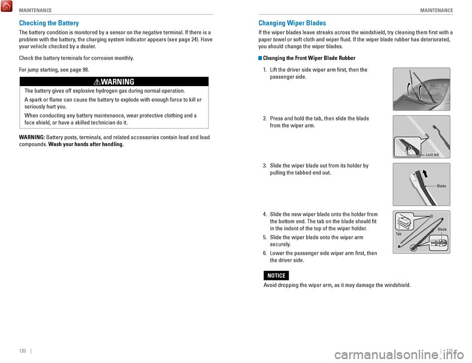
Changing the Front Wiper Blade Rubber
1.
Lift the driver side wiper arm first, then the
passenger side.
2.
Press and hold the tab, then slide the blade
from the wiper arm.
3.
Slide the wiper blade out from its holder by
pulling the tabbed end out.
4.
Slide the new wiper blade onto the holder from
the bottom end. The tab on the blade should fit
in the indent of the top of the wiper holder.
5.
Slide the wiper blade onto the wiper arm
securely.
6.
Lower the passenger side wiper arm first, then
the driver side.
Lock tab
Blade
Ta b Blade
Avoid dropping the wiper arm, as it may damage the windshield.
NOTICE
Page 68 of 76
128 || 129
MAINTENANCE
MAINTENANCE
Temperature
The temperature grades are A (the highest), B, and C, representing the\
tire’s
resistance to the generation of heat and its ability to dissipate heat w\
hen tested
under controlled conditions on a specified indoor laboratory test whee\
l. Sustained
high temperature can cause the material of the tire to degenerate and re\
duce
tire life, and excessive temperature can lead to sudden tire failure. Th\
e grade
C corresponds to a level of performance which all passenger car tires must
meet under the Federal Motor Vehicle Safety Standard No. 109. Grades B and
A represent higher levels of performance on the laboratory test wheel th\
an the
minimum required by law.
WARNING: The temperature grade for this tire is established for a tire that
is properly inflated and not overloaded. Excessive speed, underinfla\
tion, or
excessive loading, either separately or in combination, can cause heat b\
uildup
and possible tire failure.Testing of Readiness Codes
Your vehicle has readiness codes as part of the onboard self-diagnostic s\
ystem.
Some states use these codes to verify whether your vehicle’s emissions components
are working properly. The codes may not be read if you go through the emissions
testing just after the battery has gone dead or been disconnected.
To check if they are set, turn the vehicle on without starting the engine\
. The
malfunction indicator lamp will come on for several seconds. If it goes \
off, the
readiness codes are set. If it blinks five times, the readiness codes \
are not set.
If you are required to have your vehicle emissions tested before the rea\
diness codes
are set, prepare the vehicle for retesting by doing the following:
1.
Fill the gas tank to approximately 3/4 full.
2.
Park the vehicle and leave the engine off for 6 hours or more.
3.
Make sure the ambient temperature is between 40°F and 95°F (4°\
C and 35°C).
4.
Start the engine without touching the accelerator pedal, and let it idle\
for 20
seconds.
5.
Keep the vehicle in Park (P) or Neutral (manual transmission). Incre\
ase the engine speed to 2,000 rpm, and hold it there for about 3 minutes.
6.
Let the engine idle with your foot off the accelerator for 20 seconds.
7.
Select a nearby, lightly traveled major highway where you can maintain a speed
of 50 to 60 mph (80 to 97 km/h) for at least 20 minutes. Drive on the \
highway with
the vehicle in Drive (D) or 6th gear (manual transmission). Do not u\
se cruis
e
control. When traffic allows, drive for 90 seconds without using the a\
ccelerator
pedal. (Vehicle speed may vary slightly; this is OK.) If you cannot do this for
a continuous 90 seconds because of traffic conditions, drive for at le\
ast 30
seconds, then repeat two more times (for a total of 90 seconds).
8.
Drive in city or suburban traffic for at least 10 minutes. When traffi\
c conditions
allow, let the vehicle coast for several seconds without using the acceler
ator
pedal or the brake pedal.
9.
Park the vehicle and leave the engine off for 30 minutes.
The readiness codes are erased when the battery is disconnected, and set\
again
only after several days of driving under a variety of conditions.
If an emissions testing facility determines that the readiness codes are\
not set, you
may be requested to return at a later date to complete the test, or see \
your dealer.