Overhaul
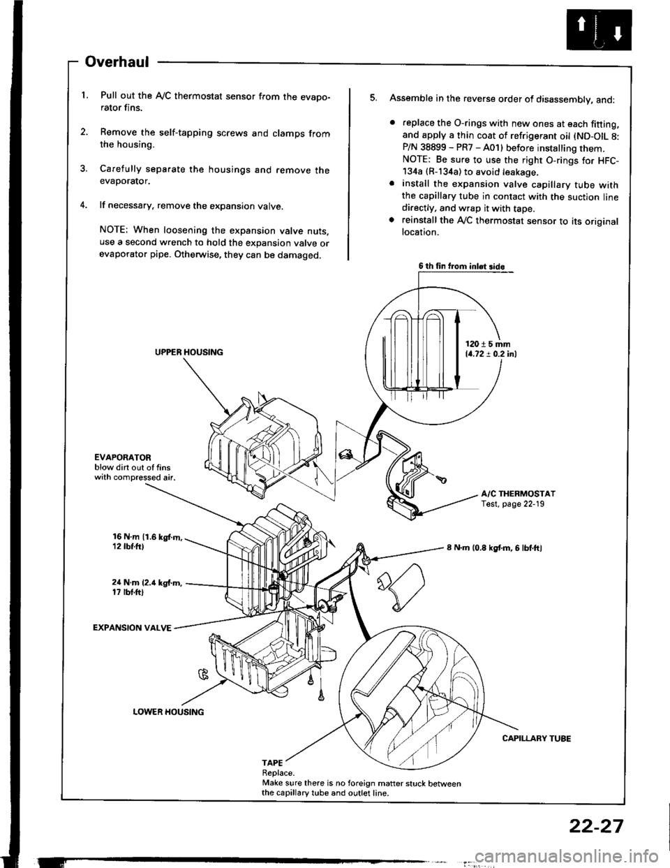
L Pull out the Ay'C thermostat sensor from the evapo-rator fins.
2. Remove the self-tapping screws and clamps fromthe housing.
3. Carefully separate the housings and remove theevaporator.
4. lf necessary, remove the expansion valve.
NOTE: When loosening the expansion valve nuts.use a second wrench to hold the expansion valve orevaporator pipe. Otherwise, they can be damaged.
Assemble in the reverse order of disassembly, and:
. feplace the O-rings with new ones at each fitting,and apply a thin coat of refrigerant oil (ND-OIL 8:P/N 38899 - PR7 - A01) before installing them.NOTE: Be sure to use the right O-rings for HFC-134a {R-134a) to avoid leakage.. install the expansion valve capillary tube withthe capillary tube in contact with the suction linedi.ectly, and wrap it with tape.. reinstall the Ay'C thermostat sensor to its originallocation.
A/C THERMOSTATTest. page 22-19
8 N.m (0.8 kgf'm, 6 lbf.ftl
CAPILLARY TUBE
5.
EVAPOAATORblow dirt out of finswith compressed air.
16 N,m 11.6 kgl.m,12 tbt.ttl
24 N.m (2.i1 kg{.m,17 rbt.ftl
EXPANSION VALVE
TAPEReplace.Make sure there is no foreign matter stuck betweenthe capillary tube and outlet line.
6 th fin trom inlet 3id6
12015 mm14.72 ! 0.2 inl
LOWER HOUSING
22-27
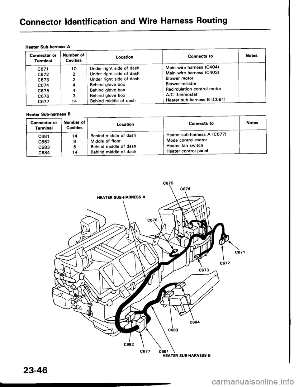
Connector ldentification and Wire Harness Routing
Hoator Sub-harneEs A
Hoator Sub-hameEs B
Connoctor or
Terminal
Numb€r of
CavitiesLocationConn6cts toNotog
c671
c672
c673
c674
c675
c676
c677
'lo
2
4
4
14
Under right side ot dash
Under right side of dash
Under right side of dash
Behind glove box
Behind glove box
Behind glove box
Behind middle of dash
Main wire harness (C404)
Main wire harness (C4o3)
Blower motor
Blower resistor
Recirculation control motot
A/C thermostat
Heater sub-harness B (C681)
connoctor 01
T6rminal
Number of
CavitioELocationConnocts toNotos
c681
c682
c683
c684
14
I
6
14
Behind middle of dash
Middle ol floor
Behind middle of dash
Behind middle of dash
Heater sub-harness A (C677)
Mode control motor
Heater Jan switch
Heater conttol Panel
HEATER SUB-HARI{ESS B
23-46
Fan Controls
Fan Motor Test
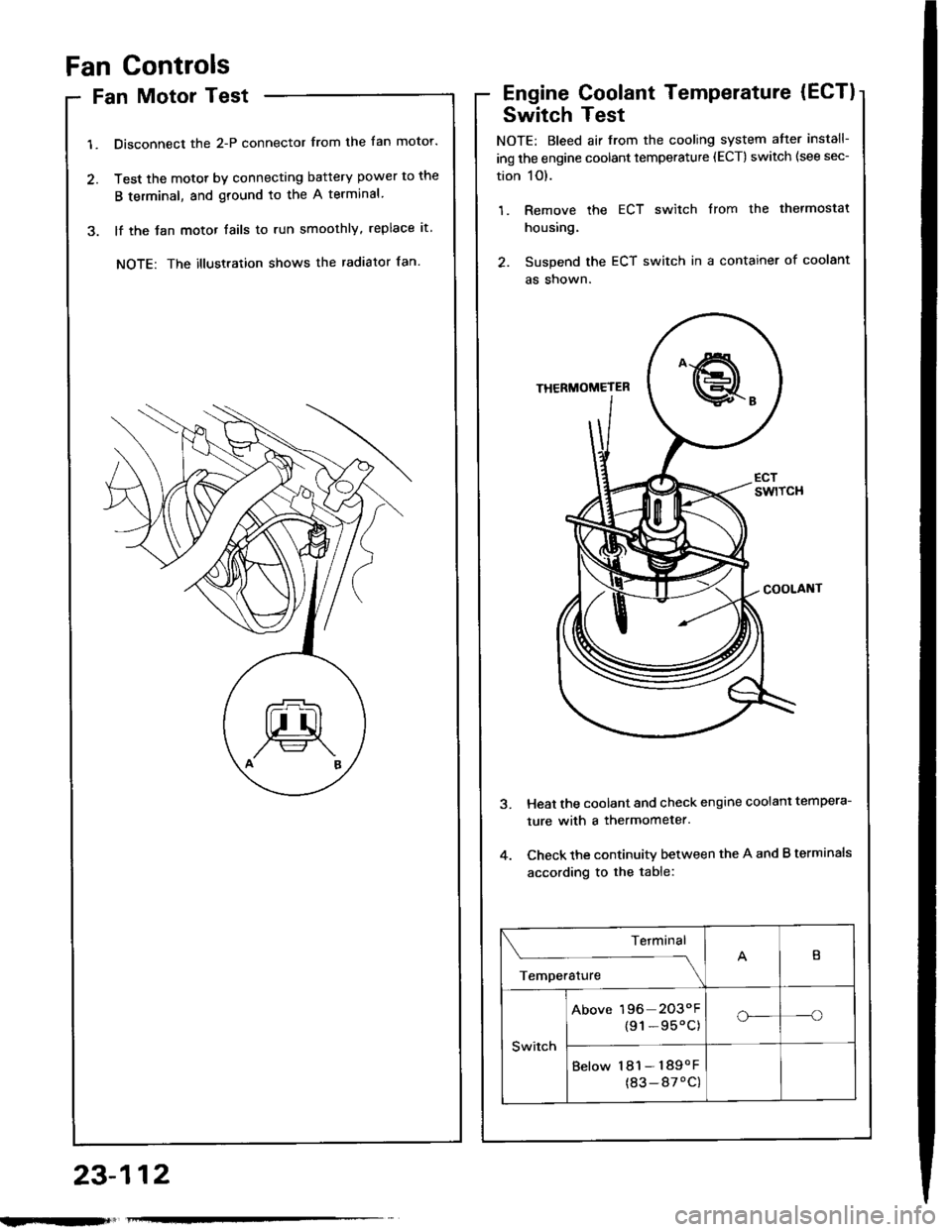
1. Disconnect the 2-P connector from the fan motor.
2. Test the motot by connecting battery power to the
B terminal, and ground to the A terminal
3. lf the Jan motor fails to run smoothly, replace it.
NOTE: The illustration shows the radiator fan.
Engine Coolant Temperature (ECT)
Switch Test
NOTE: Bleed air from the cooling system atter install-
ing the engine coolant temperature (ECT) switch (see sec-
tion 1O).
1. Remove the ECT switch from the thermostat
housing.
2. Suspend the ECT switch in a container of coolant
as shown.
Heat the coolant and check engine coolanl tempera-
ture with a thermometer.
Check the continuity between the A and B terminals
according to the table:
Terminal
;;,".,"---\
B
Switch
Above 196 2O3"F
{91-95'C)o_-o
Below 181- 189oF
(83-87'C)
23-112


