glove box HONDA INTEGRA 1994 4.G User Guide
[x] Cancel search | Manufacturer: HONDA, Model Year: 1994, Model line: INTEGRA, Model: HONDA INTEGRA 1994 4.GPages: 1413, PDF Size: 37.94 MB
Page 1094 of 1413
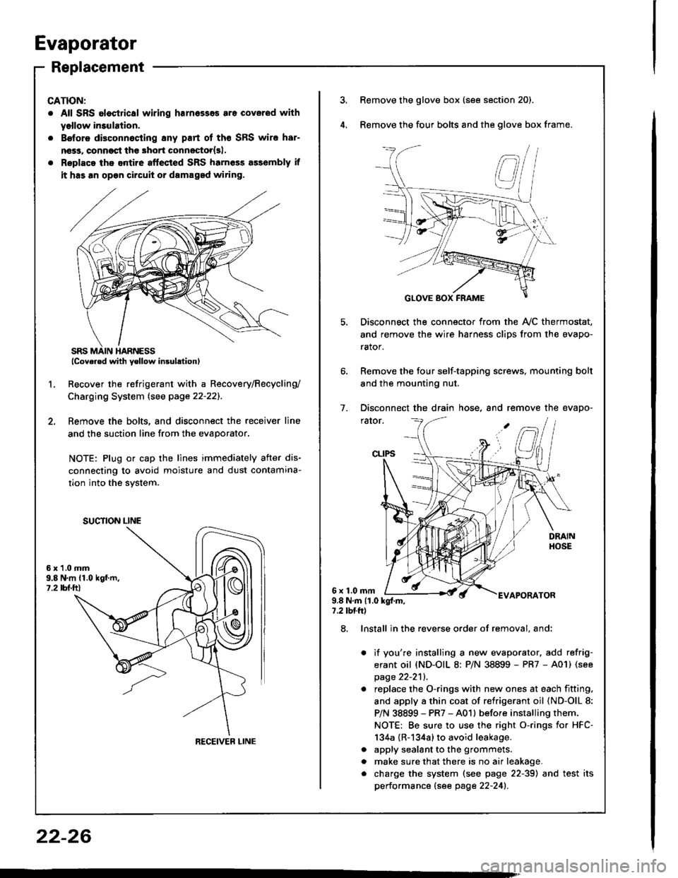
Evaporator
Replacement
CATION:
. All SRS eloctrical wiring harnesses are coverod with
yollow in3ulation.
. B€tore disconnocting 8ny part of tho SRS wire har-
nsss, conngqt th€ 3hort connestor{sl.
. Roplaca ths entire aftected SRS harness a$embly if
it has an op€n circuit or damaged wiring.
lcove.ed with yellow insulation)
Recover the refrigerant with a Recovery/Recycling/
Charging System lsee page 22-22]-.
Femove the bolts, and disconnect the receiver line
and the suction line from the evaporator.
NOTE: Plug or cap the lines immediately after dis-
connecting to avoid moisture and dust contamina-
tion into the svstem.
2.
L
6x1.0mm9.8 N.m {1.019f.m,1.2 tbl.ttl
SUCTION LINE
RECEIVEB LINE
3.Remove the glove box (see section 20).
Remove the four bolts and the glove box frame.
Disconnect the connector from the Ay'C thermostat,
and remove the wire harness clips from the evapo-
rator.
Remove the four self-tapping screws, mounting bolt
and the mounting nut.
Disconnect the drain hose, and remove the evapo-
rator.
1.
6x1.0mmAPORATOR9.8Nm{1.0kg{.m,7.2 tbtft)
a
a
8. Install in the reverse order of removal. and:
it you're installing a new evaporator, add refrig-
erant oil (ND-OIL 8: P/N 38899 - PR7 - A01) (see
page 22-2'll.
replace the O-rings with new ones at each fitting.
and apply a thin coat of refrigerant oil (ND-OlL 8:
P/N 38899 - PR7 - A01l before installing them.
NOTE: Be sure to use the right o-rings for HFC-
134a {R-134a} to avoid leakage.
apply sealant to the grommets.
make sure that there is no air leakage.
charge the system (see page 22-39) and test its
performance (see page 22-241.
22-26
Page 1107 of 1413

Electrical
Special Tools
Troubleshooting
Tips and Precautions ................................ 23-3Five-stop Tloubleshooting ..............,...-..-... Z3-sSchematic Symbols ................................_. 23-6wire Color Cod€s ..................................... 23-6Relay and Control Unit Locations
Engine Compartment .........,............ ... --. 23-7Dsshboard and Door ..,,......................... 23-gDashboard and Floor ............................. 23-t OOuaner Panel .....-.....23-12Connector ldentification and WireHarness Routing ........ 23-i 3
Index to Circuits and Systems
Airbag ............... ...-..-... 2g-26sAir Conditioning ....,.. Section 2lAltelnator ......_.............. 23-99Anti-lock Brake Systsm (ABS) Section 19Automatic Transmission Section 14Battery .............. .......... 23-66Chafging System ........... 23-98rCigalstte Lighter .....................-...-......-..-.. Z3-2O4Cfock ................. ..........23-197rcruise Controf .......--..-... 23-242Distributor .................... 23-87Fan Controls ................. 23-1ogFuel and Emissions ... Section 1i*Fuses
Under-dash Fuse/Relay Box ................... 23-48Undor-hood ABS Fuse/Retay Box ............ 23-51Under-hood Fuse/Relay Box,.................. 23-52rGauges
Engine Coolant Temperature {ECT)Gauge ................ ..23-126Fuef cauge ............... 2g-123'Gauge Assembly ....--.23-113Speedometer .....-...,,. 23-114Tachometer .....,.....-.. 23-114Ground Distribution ........ 23-60Heater ,,,........,.... ..... Section 2lrHorn ................. ........... 23-199*fgnition Switch ............. 23-70fgnition Syst6m .......-..-.. 23-A7lgnition Timing .............. 23-89Indicator Lights"A/T Gear Position .............. ................... 23-1 32B1ak6 System ...,..,..-.23-127Engine Oil Pressura .............................. _ 23-1 51Low Fuel ............ ......23-125Malfunction Indicator Lamp {MlL} ...,,. Section I l
tfnteglated Control Unit ...29-144*lnterlock System ...................................... 23-1 3gLights, Exteriol
Back-up Lights ........... 23-179Brake Lights .............. 23-t8ltDaytime Running Lights {Csnada} ........... 23-156Front Palking Lights ............................. 23-1 65Flont Side Marker Lights ....................... 23-165Front Turn Signal Lights ........................ 23-1 65*Hazard Warning Lights .........................- 2g-1A4Headlights ................. 23-t6tLicense Plate Lights .............................. 23-1 69Taillights(Harchback) .......... 23-166
{Sedan) .............. .. 23-167Lights. Inteliol
Cargo Area Light {Hatchback) ...... -.. -.. -... 23-177Ceifing Light ........-..-.23-175
Dash Lights Blightness Controt .............. 23-t70Glove Box Lighr ................................... 23-1 69Spotfighr ............ ....-.23-174Trunk Light (Sedanl ............... .............. - 23.-177*Lighting Sysrem .......-.-... 23-152:Moonroof ,,.,.......,..,,,,,.-.23-211PGM-FI Systom ........ S€crion 11Power Distribution .,.-..--..23-54Power Door Locks .............,,..................... 23-233Power Mirors ..,..,....-...- 23-216Power Relays ...........,..... 23-68Power Windows ............ 29-222*Rear Window Defogger ........,... ..........,..... - 23-20,6Reminder Systems
Key-in Remindel System ....,.............,.... 23-1 50Lights-on Reminder System ................... 23-l 5f*Maintenance Reminder system ..,,.... -.. - -. 23-.1 2gSeat Belt Reminder System ..................- 23-125*Side Markel/Turn Signal/Hazard
Ffasher System .,..,..-.23.-1A4Spark Pfugs .........-...-..... 23-97Starting System ....,,.....-. 23-73*Stereo Sound System ...,.......................,,.. 23-l gg
Supplemental Restraint System {SRS} ......... 23-265Vehicfe Speed Sensor {VSS) .............--..-.... 23-122*Wiper/Washer Systom ...............--.........-..- Zg-254
rRead SRS pi€cautions on Page 23-271 betore workingin these areas.
-+
Page 1152 of 1413
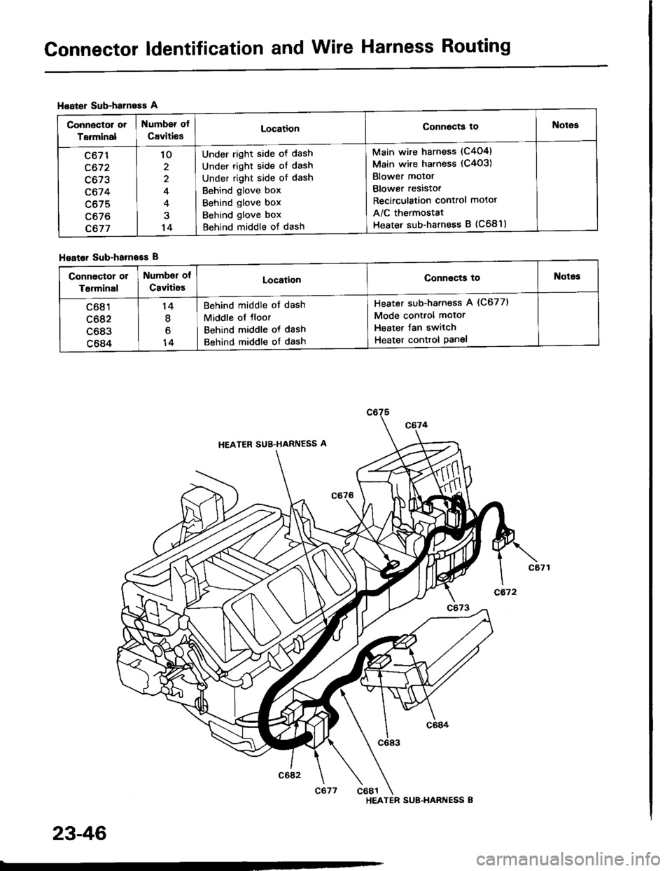
Connector ldentification and Wire Harness Routing
Hoator Sub-harneEs A
Hoator Sub-hameEs B
Connoctor or
Terminal
Numb€r of
CavitiesLocationConn6cts toNotog
c671
c672
c673
c674
c675
c676
c677
'lo
2
4
4
14
Under right side ot dash
Under right side of dash
Under right side of dash
Behind glove box
Behind glove box
Behind glove box
Behind middle of dash
Main wire harness (C404)
Main wire harness (C4o3)
Blower motor
Blower resistor
Recirculation control motot
A/C thermostat
Heater sub-harness B (C681)
connoctor 01
T6rminal
Number of
CavitioELocationConnocts toNotos
c681
c682
c683
c684
14
I
6
14
Behind middle of dash
Middle ol floor
Behind middle of dash
Behind middle of dash
Heater sub-harness A (C677)
Mode control motor
Heater Jan switch
Heater conttol Panel
HEATER SUB-HARI{ESS B
23-46
Page 1153 of 1413
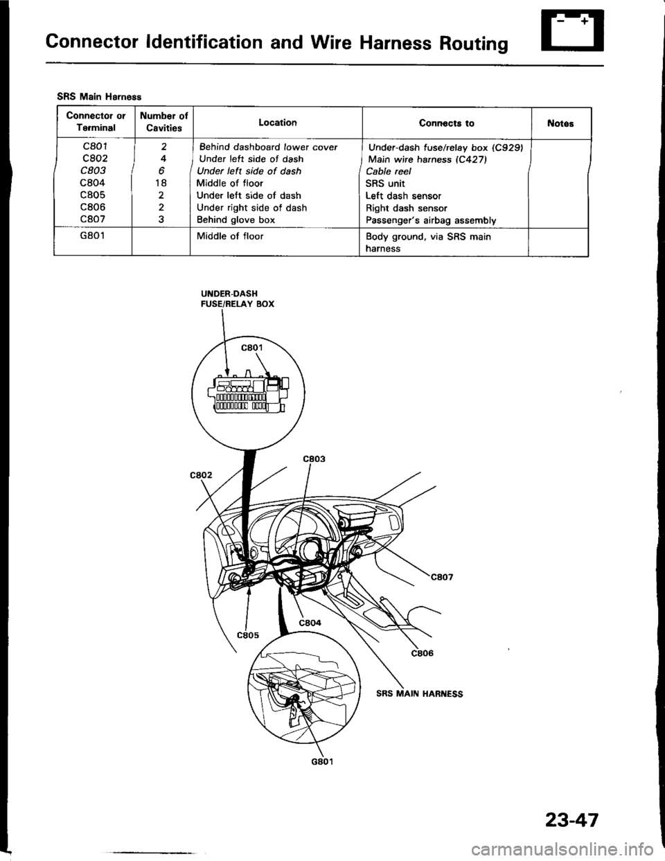
Connector ldentification and Wire Harness Routing
UNDER-DASHFUSE/RELAY BOX
SRS Main Harness
Connector or
Terminal
Number ol
CavitiesLocationConnocts tol{otos
c801
c802
c803
c804
c805
c806
c807
2
4
o
18
2
I Behind dashboard lowet cover
J Under left side of dash
Under left side of dash
Middle of floor
Under left side of dash
Under right side of dash
Behind glove box
Under-dash f use/rclay box (C929)
Main wire haness 1C427)
Cable reel
SRS unit
Left dash sensor
Right dash sensor
Passenger's airbag assembly
G801Middle of floorBody ground, via SRS main
harness
23-47
Page 1275 of 1413
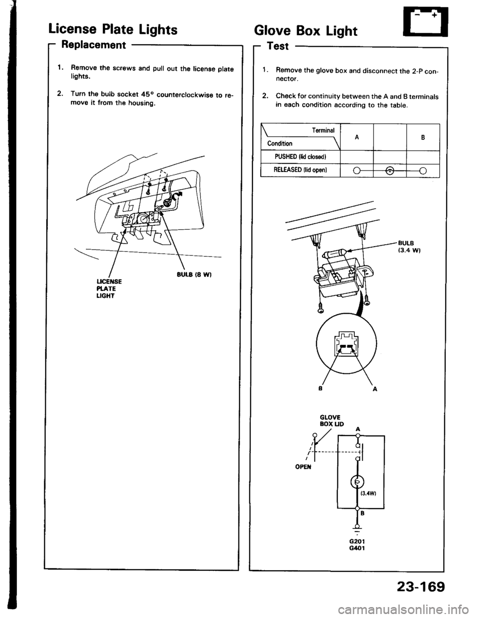
License Plate Lights
Replacement
Remov€ the screws and pull out th6 license platelights.
Turn the bulb socket 45o counterclockwise to re-move it from the housing.
ciorG4{t1
Glove Box Light
Test
Remove the glove box and disconnect the 2-p con-neclor.
Check for continuity between the A and B terminals
in each condition according to the table.
BULB(3.4 W)
Condition
T€rminalB
PUSHED {lid closodl
REI"EASED {lid oDen)o-/:\---o\7
ql-----11
dl
23-169
Page 1378 of 1413
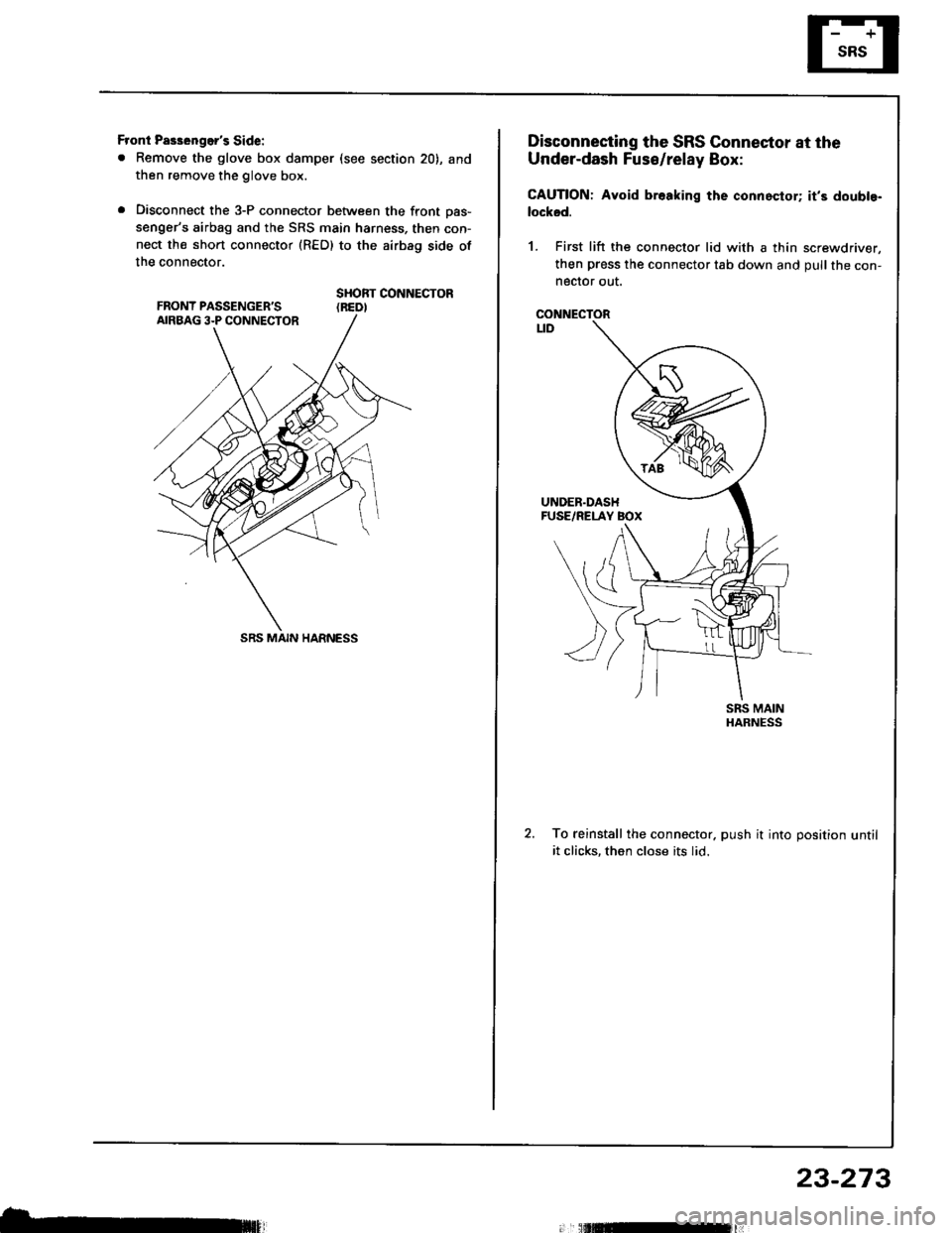
Front Pas3enger's Side:
. Remove the glove box damper (see section 20), and
then remove the glove box.
. Disconnect the 3-P connector between the front oas-
senger's airbag and the SRS main harness, then con-
nect the short connector (RED) to the airbag side of
the connector.
SHORT CONNECTOR(REDI
SRS MAIN HARNESS
b,
Disconnecting the SRS Connector at the
Under-dash Fuse/relay Box:
CAUTION: Avoid br.aking the connoctor; it's doubte-
locksd.
1. First lift the connector lid with a thin screwdriver,
then press the connector tab down and pull the con-neclor out.
CONNECTORt_tD
To reinstall the connector. push it into position untilit clicks, then close its lid.
23-273
Page 1381 of 1413
Supplemental Restraint System (SRSI
Troubleshooting
Self-diagnosis Function
The SRS unit includes a self-diagnosis function. lf there
is a failure in the sensors. SRS unit, inflator, or their cir-
cuits, the SRS indicator light in the gauge sssembly
comes ON.
As a system check, the SRS indicator light also comes
on when the ignition is first turned ON to the (ll) posi-
tion. lf the light goes off after approximately six sec-
onds, the system is OK.
lf the SRS indicator lighr remains on (or fails to come on
in the system check mode), one of the SRS components
(or the wiring/connectors inbetween) is laulty
Troubleshooting Precautions
a Always use the test harness. Do not use test probes
directly on component connector terminals or wires;
you may damage them or the SRS unit.
a When connecting any of the test harnesses to the
system, push the connectors straight-in; do not bend
the connector terminals,
. Before disconnecting any part of the SRS wire har-
ness, connect the shon connector (RED) on the driv-
er's airbag. On cars equipped with a front passen-
ger's airbag, connect short connectors on the driver's
airbag and the front passenger's airbag.
SRS Indicator Light Troubleshooting
Possiblo conditions:
1. SRS indicator light does not come on at all - see
page 23-278.
2. SRS indicator light stays on constantly - see page
23-242.
3. SRS indicator light comes on in combination with a
failure of another electrical system (charging sys-
tem light). Check for damage/corrosion at the
under-dash tuse/relay box connector.
NOTE:
. Before starting the applicable troubleshooting. check
the condition of all SRS connectors and ground
points.
. lf the fault is not found after completing the applica-
ble troubleshooting, substitute a known-good SRS
unit and check whether the indicator light goes off.
23-276
MAIN HARNESS
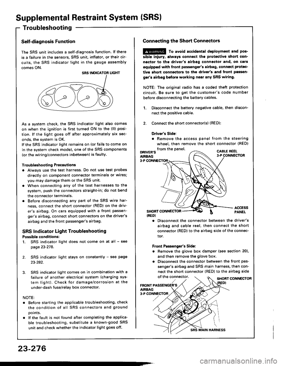
Connecting the Short Connectors
@ To avoid.ccidental doploymont and pos.
siblo iniury. alway3 connect ths protoctive short con.
noctor to tha driver's airbag connectot and, on caf!
equippod with front passongor's airbag, conncqt Prolac-
tivs ghort connoctors to the d.ivsr's and tront passsn-
gar's airbag before working nsai any SRS wiring.
NOTE: The original radio has a coded theft protection
circuit. Be sure to get the customer's code number
before disconnecting the battery cables,
Disconnect the battery negative cable, then discon-
nect the oositive cable.
Connect the short connector(s) (RED):
Drivsr's Sido:
. Romove the accoss panel trom the steering
wheel, then remove the shon connector (BED)
1.
2.
from the panel.DRIVER'SAIRBAG
CABLE R€EL
3-P
ACCESSPANELSHONT CONNESTOR(REDI
. Disconnect the connector between the driver's
airbag and cable reel, then connect the short
connector {RED} to the airbag side of the connec-
tor.
Front Pas€ngo/s Sido:
. Remove the glove box damper (see section 20),
and then remove the glove box.
. Disconnect the connector between the front pas-
senger's airbag and SRS main harness, then con-
nect the short connector (RED) to the airbag side
of the connector,SHORT CONNECTOR
Page 1400 of 1413
Airbag Assembly Replacement
@E storc a r.movcd lirb.g rslombty with thcp.d surfaco up, if tho lirbrg is improparly 3iorad frcadown, accidontal d.ploymert could plopcl tha unit withcnough torcr lo causc lariour iniury.
CAUTION:
. Do not inst.ll urld SRS plrts trom lnothar c!1,Whon lepairing, uss only now SRS prrt!.o Carefully inlpcct thc airblg rlrcmbly bltorc you
install it. Do not inst.ll an airbag !$.mbly thrt3how! sign3 of bcing droppcd or improparly hrn-dlod, such as dont!. crack3 or dstormation.. Alwry! koop ths rhort connactor(3l (REDI on thaairbrg{s} whon tho hsrnca3 i! dirconnastld.. Do not diras3ombl! or tamp€l with tha lirbrga$ombly.
NOTE: The original radio has a coded th6ft protection
circuit. Be sure to get the customer's code number
before disconnecting the battery cables.
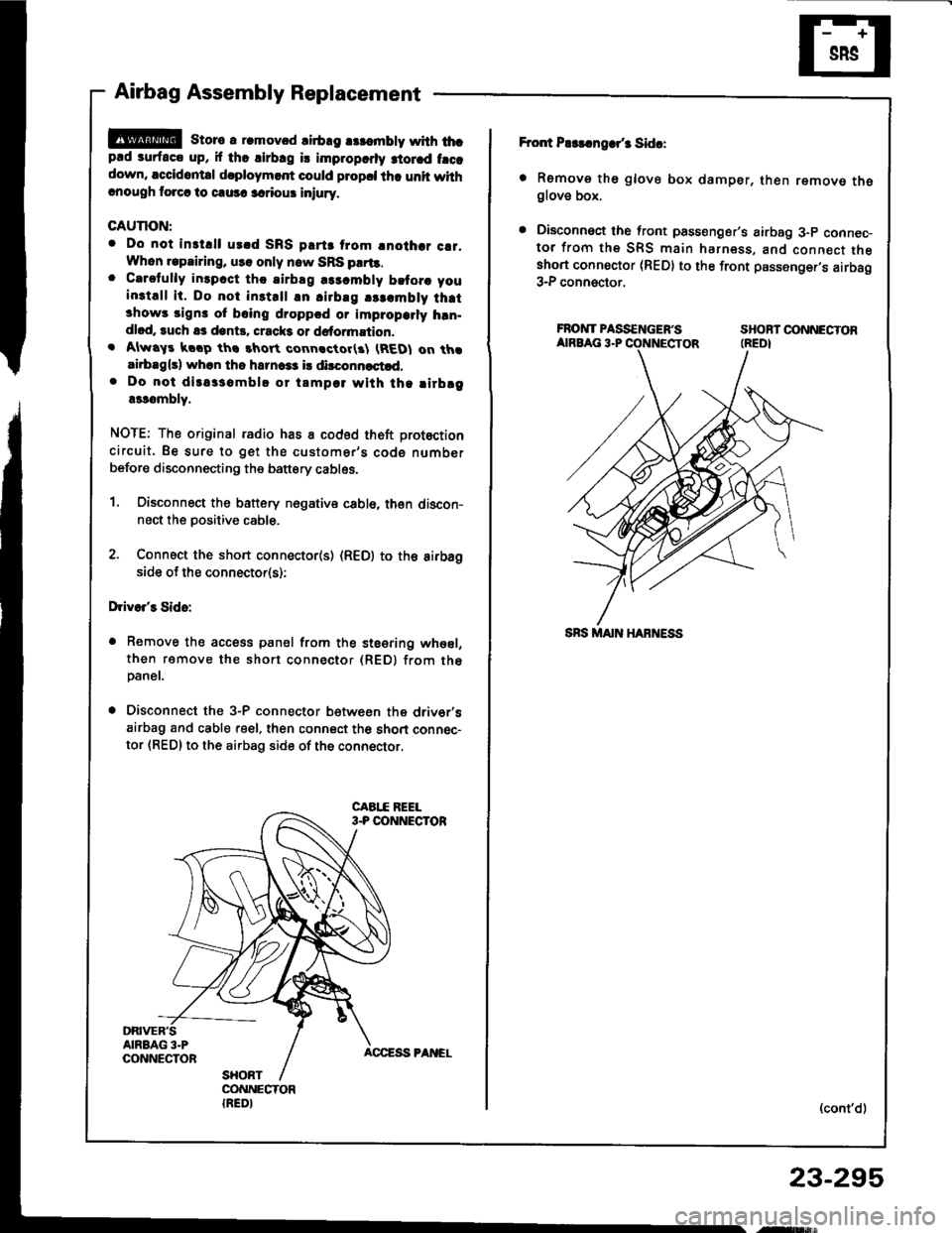
1. Oisconnect the battery nogative cabl6, then discon-nect the positive cable.
2. Connect the short connecto(s) (R€D) to the aifbagside of the connector(s);
Drivo/s Sido:
a Remove the access panel from the steering whesl,
then ramove the short connector (REDI from th6paner.
. Disconnect the 3-P connector betwesn the driv6r'sairbag and cable reel, then connect th6 short connec-
tor {RED} to the airbag side of the connector.
Fror{ P$!.ngar/3 Sida:
. Remove th6 glove box damper, then remove theglove box.
. Disconnoct the front psssenger's airbag 3-p connec-tor from the SRS main harness, and connect theshort connoctor (RED) to the front passenger,s airbag3-P connector.
FROIVTPASS€NGEF'S SHOBTOONNECTORAIRBAG 3.P CONNECTOR (REDI
(cont'd)
23-295
,ry!$,
Page 1403 of 1413
Supplemental Restraint System (SRSI
Airbag Assembly Replacement (cont'd)
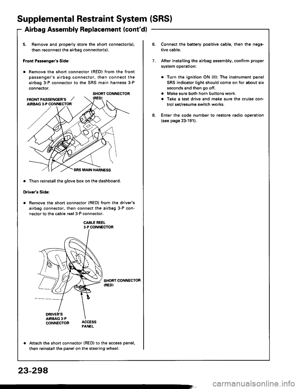
5. Remove and properly store the short connector(s),
then reconnect the airbag connector(s).
Front Pass€ng€r's Side:
. Remove the short connector (RED) from the front
passenger's airbag connector, then connect the
airbag 3-P connector to the SRS main harness 3-P
connector.
. Then reinstall the glove box on the dashboard,
Driver's Side:
Remove the short connector (RED) from the driver's
airbag connector, then connect the airbag 3-P con-
nector to the cable reel 3-P connector.
CABI-E REEL3-P CONNECTOR
SHORT CONNECTORIRED)
DRIVER'SAIRBAG 3.PCONNECTOR
Attach the short connector (RED) to the access panel,
then reinstall the panel on the steering wheel.
SHORT CONNECTOR
FRONT PASSENGER'S ,,'AIRBAG 3.P CONNECTOR
Connect the battery positive cable, then the nega-
tive cable.
After installing the airbag assembly, confirm proper
system operataon:
. Turn the ignition ON (ll): The instrument panel
SRS indicator light should come on for about six
seconds and then go off.
. Make sure both horn buttons work.
a Take a test drive and make sure the cruise con-
trol sevresum€ switch works.
Enter the code number to restore radio oDeration(see page 23-191).
7.
8.
23-294
Page 1404 of 1413
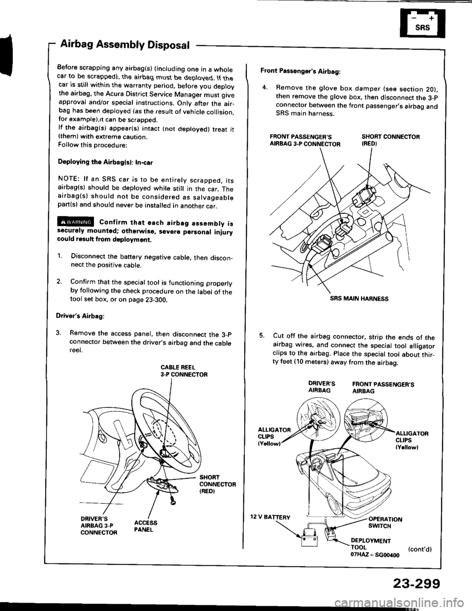
Airbag Assembly Disposal
Before scrapping any airbag(s) (including one in a wholecar to be scrappedl, the airbag must be deployed. t{ thecar is still within the warranty period, before you deplovthe ai.bag, the Acura District Service Manager must giveapproval and/or special instructions. Onlv after the air-ba9 has been deployed (as the result of vehicle collision,for example),it can be scrapped.lf the airbag(s) appear(s) intact (not deptoyed, treat it{them) with extreme caution.Follow this Drocedure:
Doploying the Airbag(sl: In-car
NOTE: lf an SRS car is to be entirely scrapped. itsairbag(s) should be deployed while still in the car. Theairbag(s) should not be considered as salvageablepan(sl and should never be installed in another car.
@ confirm that osch airbsg assembly iss6cursly mounted; oihorwis6. s€voro parsonal iniurycould result from doployment.
1. Disconnect the banery negative cable. then discon_nect the Dositive cable.
2. Confirm that the special tool is functioning properlyby following the check procedure on the label of thetool set box, or on page 23-300,
Driver's Airbag:
3. Remove the access panel, then disconnect the 3_pconnecto. between the driver's airbag and the cablereel.
CABLE REEL3.P CONNECTOR
Front Passonger's Airbag:
4. Remove the glove box damper (see section 2O).then remove the glove box. then disconnect the 3-pconnector botween the front passenger,s airbag andSRS main harness.
FRONT PASSENGER'S SHORT CONNECTORAIRBAG3.PCONNECTOR IRED}
Cut off the airbag connector, strip the ends of theairbag wires, and connect the special tool alligatorclips to the sirbag. Place the special tool about thir_ty feet (10 meters) away from the airbag.
DRIVER'S FRONTPASSENGER'SAIRBAG AIRBAG
12 V BATTERV
ALLIGATORCLIPSlY.llowl
OPERATIONswrTcH
DEPLOYMENTTOOI (cont,dl07HAZ - SG00400
23-299
SRS MAIN I{ARNESS