maintenance HONDA INTEGRA 1994 4.G User Guide
[x] Cancel search | Manufacturer: HONDA, Model Year: 1994, Model line: INTEGRA, Model: HONDA INTEGRA 1994 4.GPages: 1413, PDF Size: 37.94 MB
Page 1148 of 1413
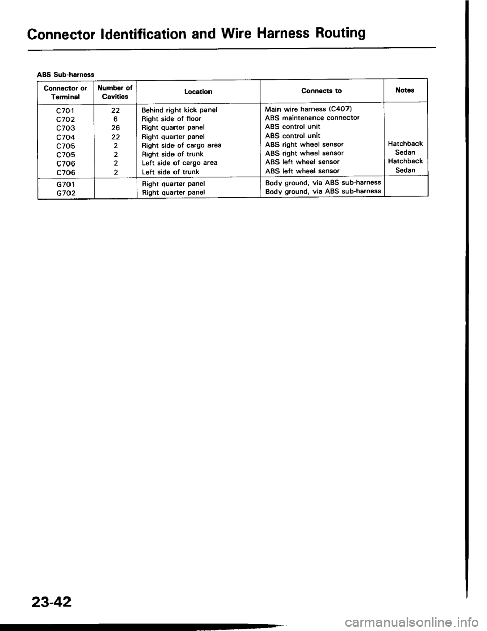
Gonnector ldentification and Wire Harness Routing
ABS Sub-harn6ss
Connactor ol
Terminal
Number of
CavitiesLocationConn€cts toNotas
c701
c702
c703
c704
c705
c705
c706
c706
22
20
22
2
2
Behind right kick panel
Right side of Jloor
Right quarter panel
Bighl quarter panel
Right side of cargo area
Right side of trunk
LeJt side of cargo area
Left side ot trunk
Main wire harness (C407)
ABS maintenance connecto.
ABS control unit
ABS control unit
ABS right wheel sensor
ABS right wheel sensor
ABS left wheel sensor
ABS left wheel sensor
Hatchback
Sedan
Hatchback
Sedan
G701
G702
Right quarter panel
Right quarter panel
Body ground, via ABS sub-harness
Body ground, via ABS sub-harness
23-42
Page 1155 of 1413
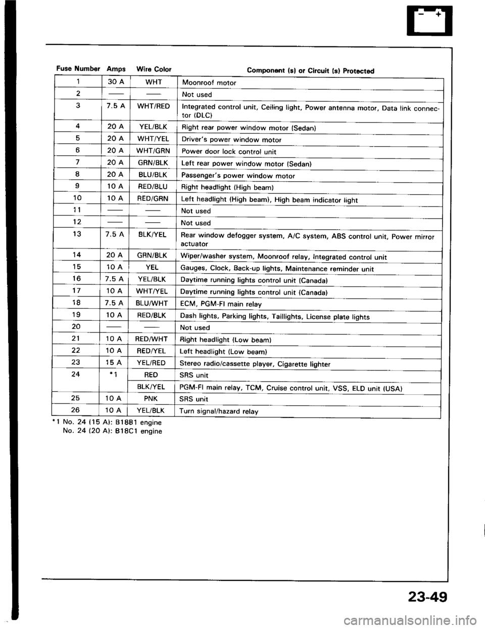
Fuse Numb€r AmDs Wire CololGomponent ls) or Circuit (s) Prot8cted
130AWHTMoonroof motor
2Not used
37.5 AWHT/REDIntegrated control unit, Ceiling light, Power antenna motor. Data link connec-tor (DLC)
420AYEL/BLKRight rea. power window motor (Sedan)
520AWHT/YELDriver's power window motor
o20AWHT/GRNPower door lock control unit
720AGRNiBLKLelt rear power window motor (Sedan)
I20ABLU/BLKPassenger's power window motor
I10 ARED/BLURight headlight {High beaml
1010 ARED/GRNLeft headlight (High beam). High beam indicato. tight
11Not used
12Not used
137.5 ABLK/YELRear window defogger system, A/C system, ABS control unit, power mrrroractuator
1420AGRN/BLKWiper/washer system, Moonroof relay, Integrated control unii'1510 AYELGauges, Clock, Back-up lights, Maintenance reminder unit
to7.5 AYEL/BLKDaytime running lights control unit (Canadal
1710 AWHT/YELDaytime running lights control unit (Csnada)
7.5 ABLU^tvHTECM, PGM-FI main relay'to10 ARED/BLKDash lights, Parking lights, Taillights, License plate tights
20Not used
2110 ARED/WHTRight headlight (Low beam)
10 ARED/YELLeft headlight (Low beam)
2315 AYEL/REDStereo radio/cassette player, Cigarette lighter
24REOSRS unit
BLK/YELPGM-FI main relay, TCM, Cruise controt unit, VSS, ELO unit IUSA)
2510 APNKSRS unit
2610 AYEL/BLKTurn signal/hazard relay'1 No.
No.
24 115 Al:
24 t2O At:.
81881 engine
B18Cl engine
23-49
Page 1158 of 1413
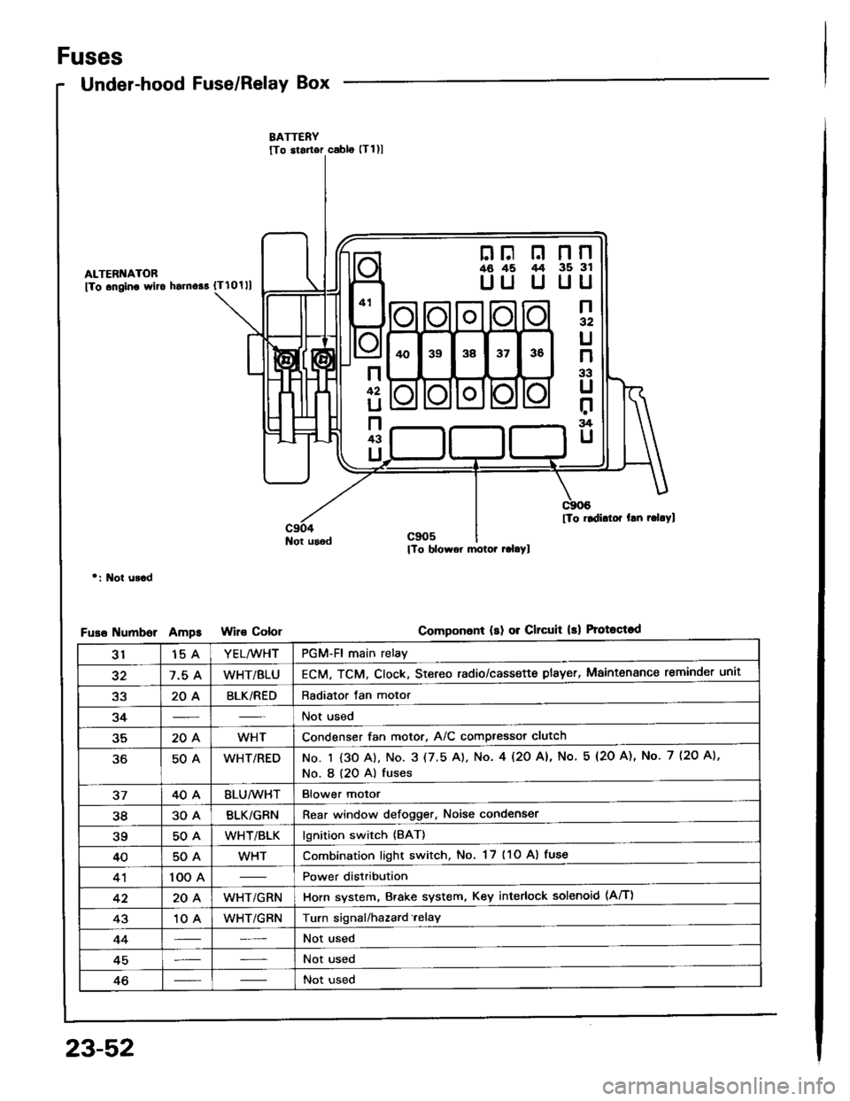
Fuses
Under-hood Fuse/Relay Box
ALTERI{ATOR
fTo .ngino wlto hsrno$ {Tlolll
Not usod
r: l\lot u3.d
umborAmpsColor
nF n nn46 45 /t4 35 3l
UU U UU
n32
U
n
33
U
r:rg
U
n
42
U
n43
U
[To rldidor hn r.l.Yl
Componon! (sl 01 Clrcuit 13) Protoqtod
3115 AYEL/WHTPGM-Fl main relay
327.5 AWHT/BLUECM, TCM. Clock, Stereo radio/cassette plsyer, Maintenance reminder unit
a2204BLK/REDRadiator Jan motor
34Not used
35204WHTCondenser fan motor, A/C compressor clutch
50AWHT/REDNo. I {3O A), No. 3 (7.5 A). No. 4l2O Al, No 5 (2O A), No. 7 (2O A),
No. I (20 A) fuses
3740ABLU/lVHTBlower motor
3830ABLK/GRNRear window defogger, Noise condenser
?q50AWHT/BLKlgnition switch {BAT}
4050AWHTCombination light switch, No. 17 (1O Al fuse
41100 APower distribution
4220AWHT/GRNHorn system, Brake system, Key interlock solenoid (Aff)
4310 AWHT/GRNTurn signal/hazard.elay
44Not used
45Not used
46Not used
23-52
Page 1221 of 1413
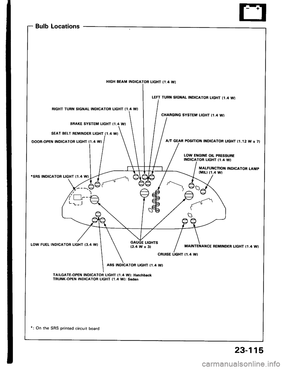
BulbLocations
HIGH BEAM INDICAL|GHT {r.4 Wl
RIGHT TURN SIGNAL INDICATOR LIGHT (I.4 W}
BBAKE SYSTEM LIGHT (1.4 W)
SEAT BELT REMINDER LIGHT I1.4 WI
OOOR-OPEN INDICATOR LIGHT {1.4 WI
iSRS INDICATOR LIGHT (1.4 W}
LOW FUEL INDICATOR LIGHT {3.4 WILIGHTS{3.4 W x 3}
ABS INDICATOR LIGHT (1.4 W}
TAILGAT€-OPEN INDICATOR I-IGHT {1.4 W): HarchbackTnUNK-OPEN INDICATOR LIGHT 11.4 W): Sodan
LEFT TURI{ SIGNAL INDICATOR LIGHT II.4 WI
CHARGING SYSTEM LIGHT II.4 WI
POSITIOII I]{DICATOR LIGHT (1.12 W x 7l
LOW EI{GII{E OIL PRESSURETOB LIGHT 11.4 WI
MALFUI{CTION INDICATOR LAMP(MrLl fi.4 wt
MAINTENANCE REMINOER LIGHT IT.4 WI
cRutsE LTGHT tl.4 Wl
*: On the SRS printed circuit board
23-115
Page 1234 of 1413
Maintenance ReminderSystem
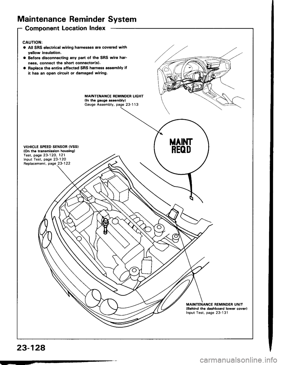
Gomponent Location Index
23-128
CAUTION:
a All SRS eloctrical wiring haln€sses are coveled with
y€llow insulation.
a Bsfore disconnocting any part of the SRS wire har-
ne6a, connect tho shon connoctor(s).
a Replace the entire affoctod SRS hsrness ass6mbly if
it has an open circuil or damag€d wiring.
MAINTENAf{CE REMINDER LIGHT(ln th6 gaugo 63.smblylGauge Assembly. page 23-113
VEHICLE SPEED SENSOR {VSS){On the t.ansmirsion houainglTest, page 23-120, 121Input Test, page 23-120Repfacement, page 23-122
MAINTENANCE REMINDER UNITlBohind tho dashboard lowor covor)Input Test, page 23-131
MAINT
REOD
Page 1235 of 1413
Description
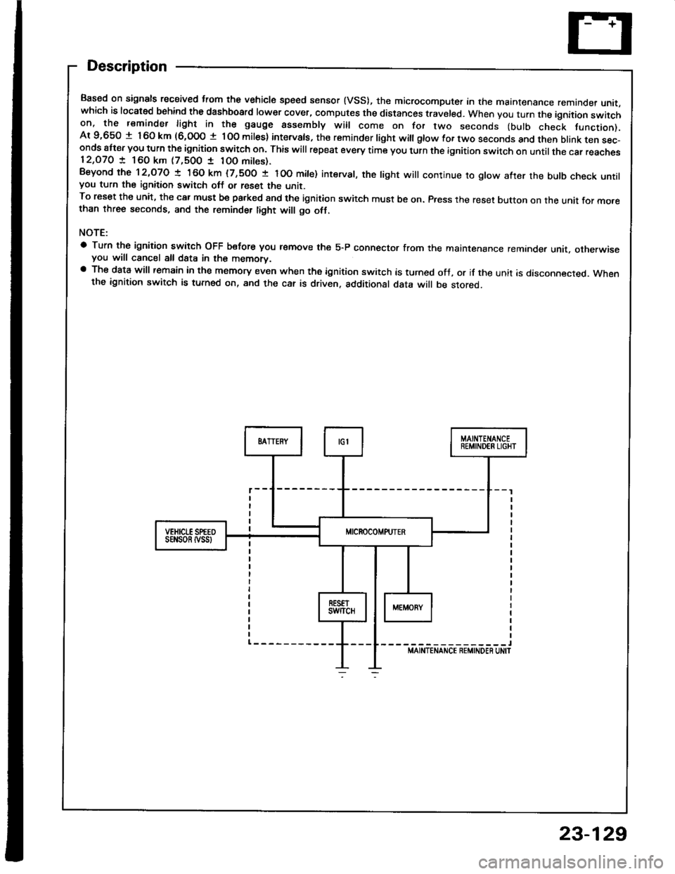
Based on signals recaived trom the vehicle speed sensor (VSS), the microcomputer in the maintenance remande, unit,which is located behind the dashboard lower cover, computes the distances traveled. When you turn the ignition switchon, the reminder light in the gauge assembly will come on for two seconds (bulb check tunction).Ar 9,650 t 160 km (6,000 t lOo miles) intervals, the reminder light witl gtow for two seconds and then btank ten sec-onds att€r you turn the ignition switch on. This will repeat every time you turn the ignition switch on until the car reaches12,O7O ! 160 km (7,500 1 10O mites).Beyond the 12,O7O ! 160 km (7,500 t IOO mite) interval, the tight will continue ro gtow after the butb check untilyou turn the ignition switch off or reset the unit.To reset the unit, the car must be pa.ked and the ignition switch must be on. Press the reset button on the unit for mo.ethan three seconds, and the reminder tight will go otf.
NOTE:
a Turn the ignition switch OFF b€fore you r€move the 5-P connector from the maintenance reminder unit. otherwiseyou will cancel all data in the memorv.a The data will remain in the memory even when the ignition switch is turned ofJ, or if the unit is disconnected. Whenthe ignition switch is turned on, and the car is driven. additional data will be stored.
-----------------lMAINTENANCE REMINDEN UN|T
sEt{son tvss
23-129
Page 1236 of 1413
Maintenance Reminder System
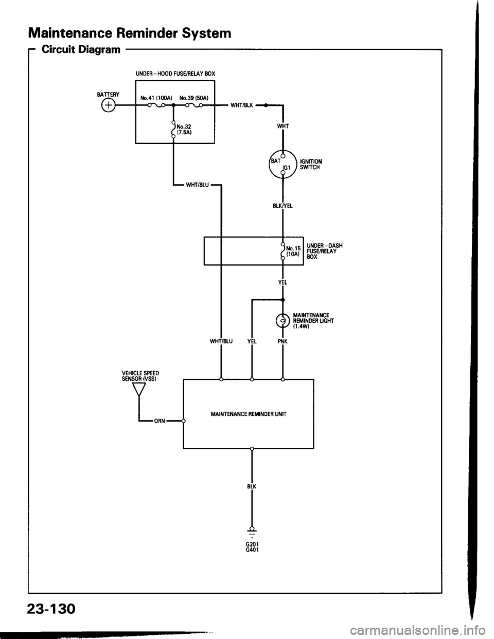
Circuit Diagram
23-130
UNDER-HOOD FUSE/REIAY 8OX
MAINIET,IAT,ICE REMINOER UiIIT
Page 1237 of 1413
Maintenance Reminder Unit Input Test
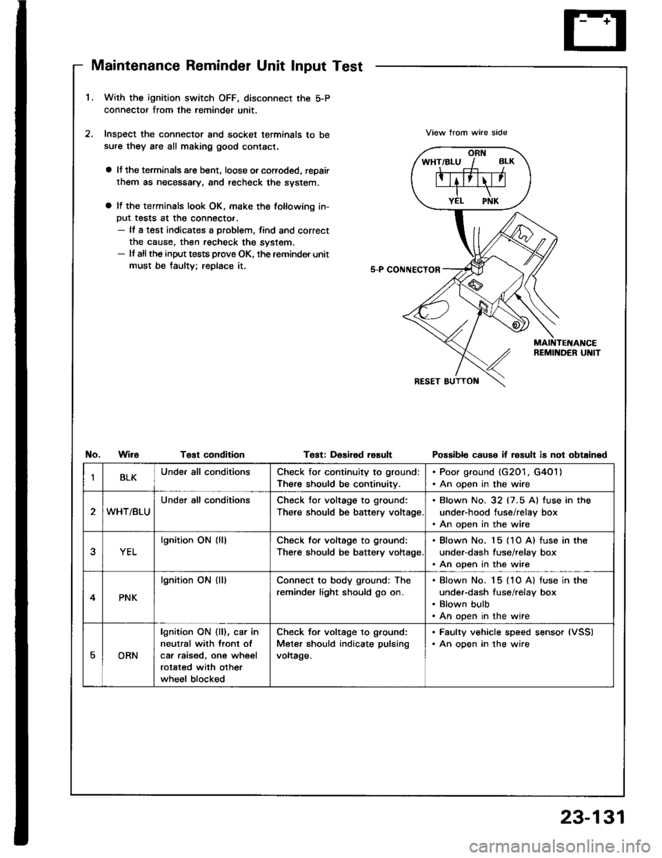
1.With the ignition switch OFF, disconnect the 5-P
connector from the reminder unit,
Inspect the connector and socket terminals to be
sufe they are all making good contact.
a lJ the terminals are bent, loose orcorroded, repair
them as necessary, and recheck the svstem.
a It the terminals look OK, make the following in-
Put tests at the connecto..- lf a test indicates a problem, tind and correct
the cause, then recheck the system.- It allthe input tests prove OK, the reminder unit
must be taulty; replace it.
View trom wire side
No.WireTost condltionTest: DaEired rasultPossibl€ cause if result is not obtained
IBLKUnde. all conditionsCheck for continuity to ground:
There should be continuitv.
. Poor ground (G201, G4O1). An open in the wire
WHT/BLU
Under all conditionsCheck tor voltage to ground:
There should be battery voltage
. Blown No. 32 (7.5 A) fuse in the
under-hood tuse/relay box. An open in the wire
YEL
lgnition ON (lllCheck for voltage to ground:
There should be batte.y voltage
. Blown No. 15 (1O A) fuse in the
under-dash fuse/relay box. An open in the wire
4PNK
lgnition ON (ll)Connect to body ground; The
reminder light should go on.
Blown No. 15 (1O A) tuse in the
under-dash fuse/relay box
Blown bulb
An open in the wire
EORN
lgnition ON {ll), car in
neutral with lront ol
car raised, one wheel
rotated with other
wheel blocked
Check for voltage to g.ound:
Meter should indicate pulsing
voltage.
. Faulty vehicle speed sensor (VSS)
. An oDen in the wire
23-131