turn signal HONDA INTEGRA 1994 4.G User Guide
[x] Cancel search | Manufacturer: HONDA, Model Year: 1994, Model line: INTEGRA, Model: HONDA INTEGRA 1994 4.GPages: 1413, PDF Size: 37.94 MB
Page 273 of 1413
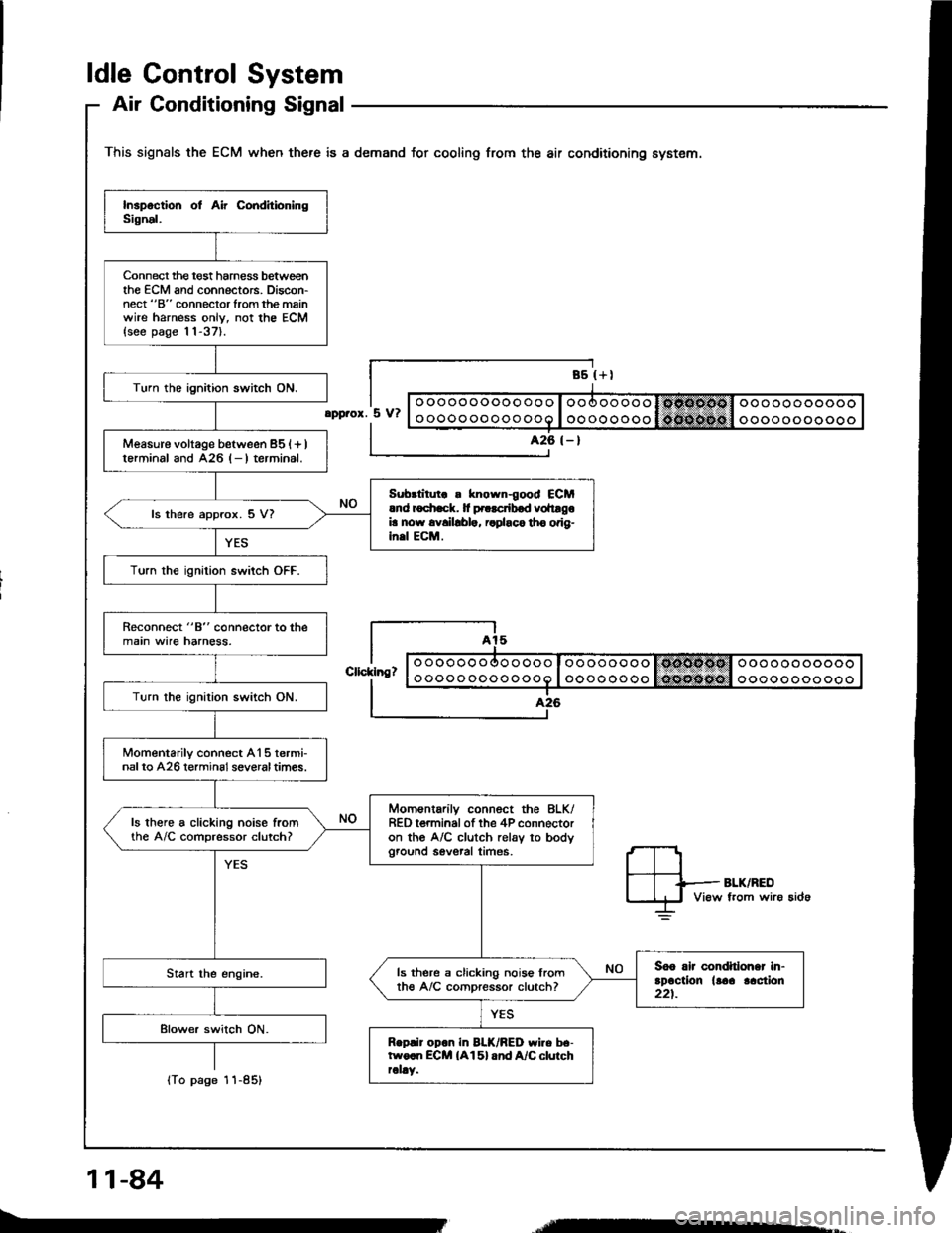
ldle Gontrol System
Air Conditioning Signal
This signals the ECM when there is a demand for cooling from the air conditioning system.
Connect the t€st harness betweenthe ECM and connectors. Discon-nect "B" connector from the mainwire harness onlv, not the ECM{see page 11-37}.
Turn the ignition switch ON.
Measure voltage between 851+ )lerminal and A26 l- I terrninal.
Sub.litut ! known{ood €CMrnd r6
Turn th€ ignition switch OFF.
Reconnect "8" connector to themain wire harness.
Turn the ignilion switch ON.
Momentarilv connect A15 termi-nalto A26 terminsl severaltimes.
Momsntarilv connect the 8LK/RED t€rminal of the 4P connectoron the A/C clutch rel6v to bodyground sevsral times.
ls there a clicking noise fromthe A/C comDressor clutch?
3o6 rlr condhlohar in-rDactlon llaa lac{ion221.
ls there a clicking nois€ lromth€ A/C comoressor clutch?
Rop.ir opon in BLK/BED wiro be-two.n ECM {A15} and A/C clurchrally.
ooooooooooooo
oooooooooooo
oooooooo
oooooooo
ooooooooooo
ooooooooooo
.pprox. 5 V?
426 (- )
Cllcklng?
lTo page
11-84
-
Page 275 of 1413
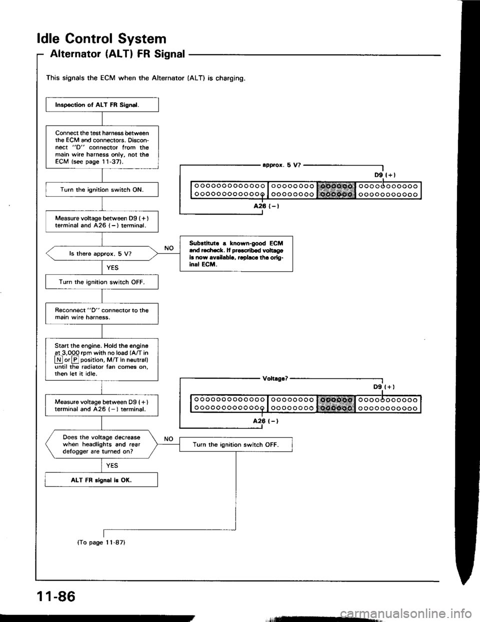
ldle Control System
Alternator (ALTI FR Signal
This signals the ECM when the Alternator (ALT) as charging.
D9 l+)
Inspection ot ALT FR Sign.l.
Connect the tost harness betweenthe ECM and connectors. Discon-nect "D" connector from themain wire harnoss only, not theECM lsee page 11-37).
Turn the ignition switch ON.
Measure voltage between D9 (+ )terminal and A26 {-}terminal.
Sub{inno s known-good ECMand redrack. It pro.ctibod volt gola now availablg, ropllco tha orlg-inal ECM.
ls there approx. 5 V?
Turn the ignition switch OFF.
Reconnect "D" connector to themain wire harness,
Start tho engino. Hold the engine
!L3,099 rpm with no load (A/T in
LN] or El position, M/T in neutral)until the radiator tan comes on,rhen let it idle.
Measuro voltage between Dg (fl
terminal and 426 (- I terminal.
Does the voltage decreasewhen headlights and .eardelogger are turned on?Turn ths ignition switch OFF.
ALT FR rignal is OK.
o oo oo o ooooo
ooooooooooo
Voh.go?
ooooooooooo
ooooooooooo
1 1-86
(To page 1 1-87)
=-
Page 277 of 1413
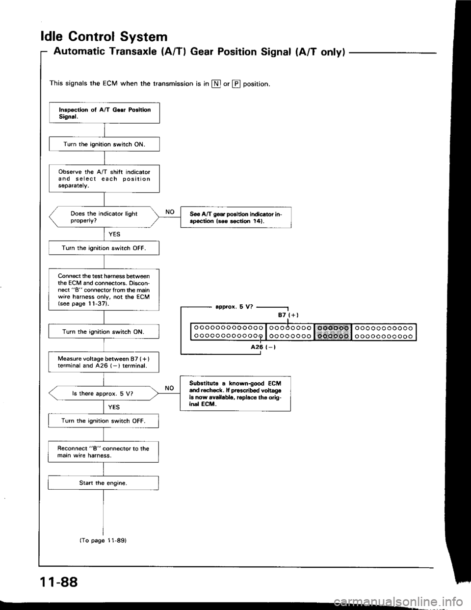
ldle Control System
Automatic Transaxle {A/Tl Gear Position Signal {A/T onlyl
This signals the ECM when the transmission is in @ or @ position.
appror. 5 V?
1 1-88
-.
87 l+)
ooooooooooooo
oooooooooooo
A26 {-}
Turn the ignition switch ON.
obsorve the A/T shift indicatorand s eiecl each positionseparately.
Soo A/T goa. position indicator in-spoqtion ls6o lection 141.
Turn the ignition switch OFF.
Connect the test hamess betweenthe ECM and connectors. Discon-nect "B" connoclorlrom the mainwire harness only, not the ECM(see page 11-37).
Turn the ignition switch ON.
Measure voltage between 87 (+ Iterminal and 426 1- ) terminal.
Subslituto . known-good ECM6nd .ech6ck. lf pr63cribod voltageia now availablo, rcplaco ths o.ig-inel ECM.
ls there approx. 5 V?
Turn the ignition switch OFF.
Reconnect "8" connector lo lhemaan wire harness.
(To page 11-89)
Page 282 of 1413
![HONDA INTEGRA 1994 4.G User Guide Power Steering Pressure (PSP) Switch Signal
This signals the ECM when the power steering load
-;"nection.*."------.ill]
--
;;;;;;;l w
;:"r"tffa;i
connecrors (see
Turn the ignition switch ON.
Measur HONDA INTEGRA 1994 4.G User Guide Power Steering Pressure (PSP) Switch Signal
This signals the ECM when the power steering load
-;"nection.*."------.ill]
--
;;;;;;;l w
;:"r"tffa;i
connecrors (see
Turn the ignition switch ON.
Measur](/img/13/6067/w960_6067-281.png)
Power Steering Pressure (PSP) Switch Signal
This signals the ECM when the power steering load
-;"nection.*."------'.ill]
--
;;;;;;;l w
;:"r"tffa;i'
connecrors (see
Turn the ignition switch ON.
Measure voltage between 88 {+ )terminal and A26 {-) terminal.
is high.
o ooooo oooo ooo I oo ooo oo o l.Do€d(iltl ooooooooooo
o oooo ooo ooooQ I oooQ oo oo $aG$ast.l oooooooo oo
A26 l-) Bg l+l
L6s! thsn l.O V?
wire side
Turn the ignition switch OFF.
Disconnect the 2P connector tromthe PSP switch.
ls there less than 1.0 V?
Tu.n the ignition switch ON.
Turn steering wheel slowly.ls there less than 1.O V?
Measure voltage between B8 (+)
terminal and 426 (-) termanalwhile steering wheel is turning.
Ropair opon in GRN wire betwssnECM {88} and PSP srYilch ot BLKwi.o botw6cn PSP switch andG301 (locatod at loft ongin6 com-partm6ntr.
Disconnect the 2P connector lromthe PSP switch.PSP switch signal is OK.
Repair short in GRN wi.e botwoonECM {881 and PSP switch.ll wiro i3 OK, substitute a known-good ECM and.ocheck. lIproscribod vollage is now available, replaco tho original ECM.
GRN
PSP SWITCH
11-93
Page 301 of 1413
![HONDA INTEGRA 1994 4.G User Guide Fuel Supply System
PGM-Fl Main Relay (contdl
BLU
BLU/wHt
Bt-xNOTE:. M/T: Clutch pedal mustbe depressed.. A/T: Transmission in
N or E] position.
BLK/ YEL/YEL BLK
Tloubloshooting
{To page 11 113}
- Eng HONDA INTEGRA 1994 4.G User Guide Fuel Supply System
PGM-Fl Main Relay (contdl
BLU
BLU/wHt
Bt-xNOTE:. M/T: Clutch pedal mustbe depressed.. A/T: Transmission in
N or E] position.
BLK/ YEL/YEL BLK
Tloubloshooting
{To page 11 113}
- Eng](/img/13/6067/w960_6067-300.png)
Fuel Supply System
PGM-Fl Main Relay (cont'dl
BLU
BLU/wHt
Bt-xNOTE:. M/T: Clutch pedal mustbe depressed.. A/T: Transmission in
N or E] position.
BLK/ YEL/YEL BLK
Tloubloshooting
{To page 11 113}
- Engino will not sran.- Inspection oI PGM-FI main re-lay and rolay ha.n6!a.
Check lor continuitv between BLKterminal @ and body ground.
Rapair open in BLK wire botwoonPGM-FI main.el6y and GIO'l llo-catod at thormostot housingl.
Measure the voltage betweenYELMHT terminal @ and bodyground.- Roplaco th. ECU IECMI(15 Allus6 in tho under-hood fu!o/r6-lay box.- Ropair opan or short in theYEL/WHT wil6 botwosn thePGM-FI main rolay and the ECU
{EcMl 115 A} luso.
ls there battery voltage?
Turn the ignition switch ON.
Measure the voltage betweenBLK/YEL terminal @ and bodyground.- Reolac. ths No. 24 ACG {ALT}{lcl {15 A:81881 6ngino, 20A: Bl8Cl engin6) tuse in thoundor-dash fuso/rolaY box.- Ropaii op6n or rhon in thoBLK/YEL wiro botwoen thoPGM-FI main ielay and th€ No.24 ACG {ALT) flG} {'�15 A:818Bi ongine, 20 A: 818Cionginol fuso.Turn the ignition switch to theSTART position.
Measure the voltage betweenBLUMHT terminsl @ and bodyground.
- Replaco the l\lo. 18 STARTERSIGNAL {7.5 A} fuso in thoundor-dash fuaa/rolay box.- R6pai. open or short in thoBLU/WHT wire botweon thsPGM-FI main relay and tho No.1A STARTER SIGNAL I7.5 AIluse.
11-112
Page 411 of 1413
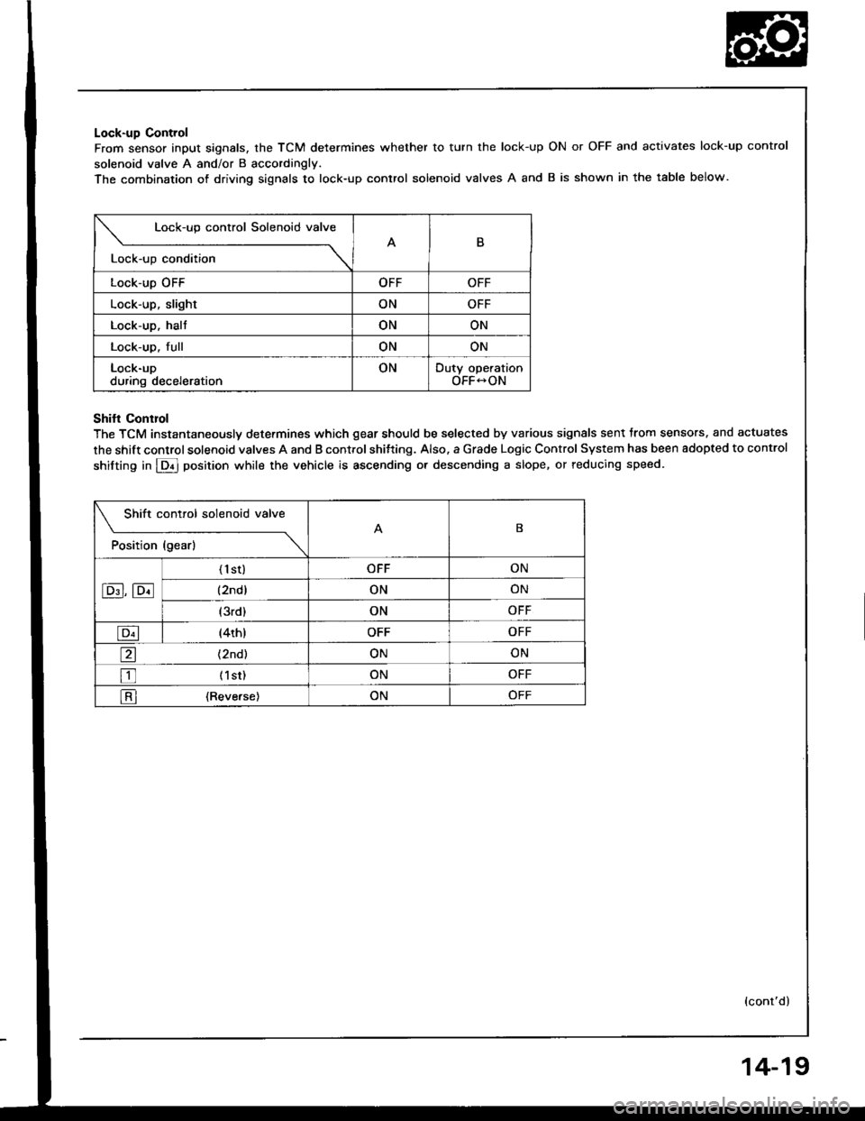
Lock-up Control
From sensor input signals, the TCM determines whether to turn the lock-up
solenoid valve A and/or B accordingly.
The combination of driving siqnals to lock-up control solenoid valves A and
ON or OFF and activates lock-up control
B is shown in the table below.
Lock-up control Solenoid valve
B
Lock-up condition \
Lock-up OFFOFFOFF
Lock-up, slightONOFF
Lock-up. haltONON
Lock-up. fullONON
Lock-upduring decelerationONDuty operationOFF-ON
Shifl Conrrol
The TCM instantaneously determines which gear should be selected by various signals sent trom sensors. and actuates
the shift control solenoid valves A and B control shitting. Also. a Grade Logic Control System has been adopted to control
shifting in E] position while the vehicle is ascending or descending a slope, or reducing speed.
Shift control solenoid valve
t"*b" ,t"-l
------\B
E,E
('l st)OFFON
(2ndlONON
(3rd)ONOFF
E(4th)OFFOFF
a(2nd)ONON
tr (lst)ONOFF
l-Rl {Reverse)ONOFF
(cont'd)
14-19
Page 428 of 1413
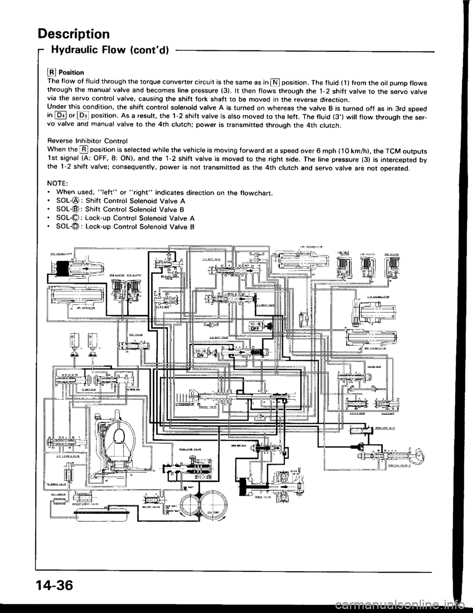
Description
Hydraulic Flow (cont'd)
LEI Position
The flow ot fluid through the torque convener circuit is the same as in S position. The tluid ( 1 ) trom the oil pump flowsthrough the manual valve and becomes line pressure (31. lt then flows through the 1-2 shift valve to the servo varvevia the servo control valve, causing the shift tork shatt to be moved in the reverse direction.Under this condition, the shift control solenoid valve A is turned on whereas the valve B is turned ofJ as in 3rd speedin [Dil or lDs]l position. As a result, the 1-2 shift valve is also moved to the left. The ftuid (3'] will ftow through the ser-vo valve and manual valve to the 4th clutch; power is transmitted through the 4th clutch.
Reverse Inhibitor Control
When the @ position is selected while the vehicle is moving forward at a speed over 6 mph ( 1O km/h). the TCM outputs1st signal (A: OFF, B: ON), and the 1-2 shift valve is moved to the right side. The line pressure {3) is intercepted bvthe 1-2 shift valve; consequently, power is not transmitted as the 4th clutch and servo valve are not oDerareo.
NOTE:. When used, "lefl" ot "tight" indicates direction on the flowchart.. SOL-@: Shift Control Solenoid Valve A. SOL€: Shift Control Solenoid Valve B. SOL€: Lock-up Control Solenoid Vatve A. SOL-@: Lock-up Control Sotenoid Vatve B
14-36
Page 443 of 1413
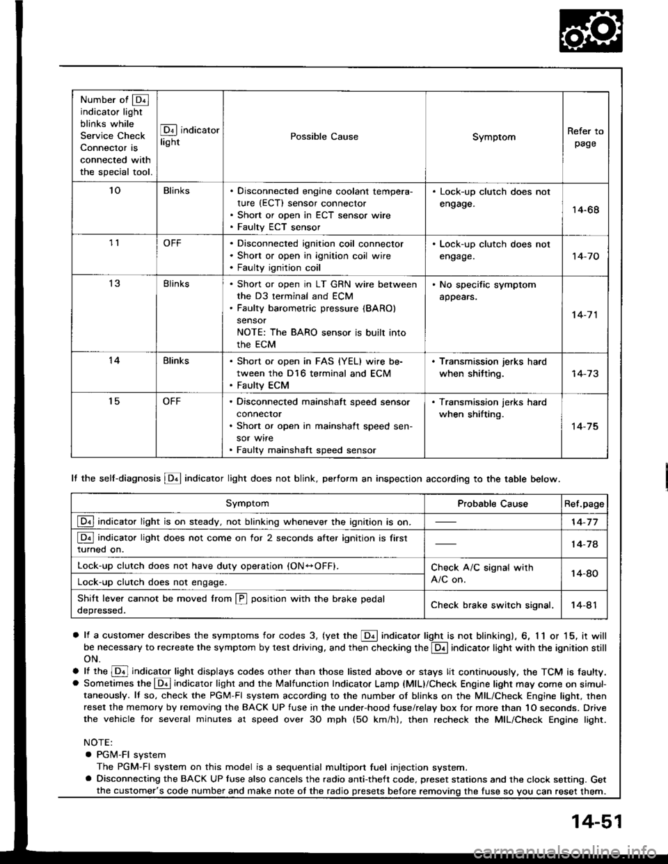
Number of @indicator light
blinks while
Service Check
Connector is
connected with
the special tool.
@ indicator
lightPossible CauseSymptomRefer to
page
'loBlinksDisconnected engine coolant tempera-
rure (ECT) sensor connector
Short or open in ECT sensor wire
Faulty ECT sensor
Lock-up clutch does not
engage.14-68
1lOFFDisconnected ignition coil connector
Short or open in ignition coil wire
Faulty ignition coil
. Lock-up clutch does not
engage.'t 4-7 0
13Blinks. Shon or open in LT GRN wire between
the D3 terminal and ECM. Faulty barometric pressure {BARO)
sensor
NOTE: The BARO sensor is built into
the ECM
. No specific symptom
appears.
14-7 1
14Blinks. Short of open in FAS {YEL} wire be-
tween the D16 terminal and ECM. Faulty ECM
. Transmission jerks hard
when shitting.
't5OFFDisconnected mainshaft speed sensor
connecror
Short or open in mainshaft speed sen-
sor wire
Faulty mainshaft speed sensor
. Transmission jerks hard
when shifting.
14-75
SymptomProbable CauseRet.page
LQ! indicator light is on steady, not blinking whenever the ignition is on.14-77
[Q3] indicator light does not come on for 2 seconds after ignition is first
turned on.14-78
Lock-up clutch does not have duty operation (ON-OFFI.Check A/C signal with
A/C on.14-80Lock-up clutch does not engage.
Shitt leve. cannot be moved lrom @ position with the brake pedal
depressed.Check brake switch signal,14-41
It the self-diagnosis LQ4 indicator light does not blink, perform an inspection according to the table below.
a lf a customer describes the symptoms for codes 3, (yet the LQ! indicator light is not blinkingl, 6, 1 1 or 15, it will
be necessa.y to recreate the symptom by test driving. and then checking the @ indicator light with the ignition still
oN.
e lt ttre @ indicator light displays codes olher than those listed above or stays lit continuously, the TCM is faulty.. Sometimes the Lqd indicator light and the Malfunction Indicator Lamp (MlL)/Check Engine light may come on simul-taneously. lf so, check the PGM-Fl system according to the numbe. of blinks on the MIL/Check Engine light. thenreset the memory by removing the BACK UP fuse in the unde.-hood fuse/relay box for more than 1O seconds. Drive
the vehicle for several minutes at speed over 30 mph (5O km/h), then recheck the MIL/Check Engine light.
NOTE:
. PGM-FI system
The PGM-Fl system on this model is a sequential multiport fuel injection system.a Disconnecting the BACK UP luse also cancels the radio anti-theft code. preset stations and the clock setting. Get
the fuse so vou can reset them.the customer's code number and make note ot the radio
14-51
Page 635 of 1413
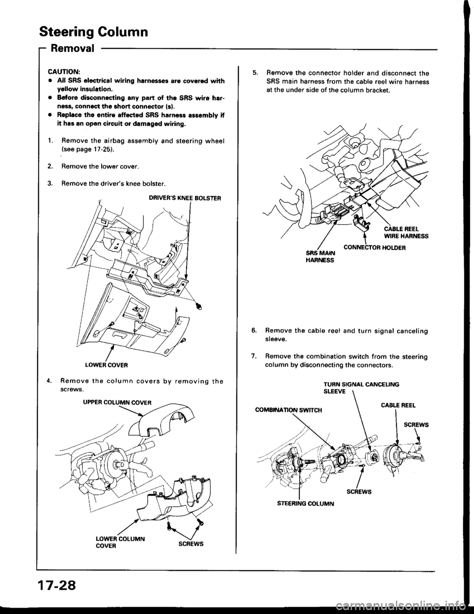
Steering Golumn
Removal
LOWER COVER
Remove the column covers
screws.
CAUTION:
. All SRS el€ctrical wiring hlrnesses are coversd withyollow insuhtion.
. Bctore dieconnocting any part ol tho SRS wiro h!r-
nesa, connoct the thort connector (s).
. Roplace tho ontire aftected SRS harness asr€mbly if
it has !n open circuit or d!mlgod wiring.
Remove the airbag assembly and steering wheel
.(see page 17-25).
Remove the lower cover.
Remove the driver's knee bolster.
by re mov in g the
17-2A
scREws
5. Remove the connector holder and disconnect the
SRS main harness from the cable reel wire ha.ness
at the under side ot the column bracket.
HARNESS
Remove the cable reel and turn signal canceling
steeve.
Remove the combination switch from the steering
column by disconnecting the connectors,
TURN SIGNAL CANCELINGSlTEVE
COMA|NANON SW]TCH
7.
CABI..E REEL
STEERING COLUMN
Page 640 of 1413
7.
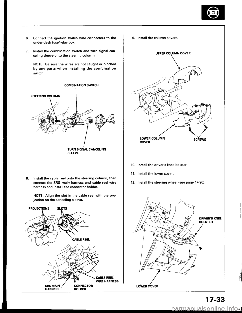
Connect the ignition switch wire connectors to the
under-dash fuse/relav box.
Install the combination switch and turn signal can-
celing sleeve onto the steering column.
NOTE: Be sure the wires are not caught or pinched
by any parts when installing the combination
switch.
TURN SIGNAL CANCELINGSLEEVE
Install the cable reel onto the steering column, then
connect the SRS main harness and cable reel wiro
harness and install the connector holder.
NOTE: Align the slot in the cable reel with the pro-
jection on the canceling sleeve.
coMatNATroN swncH
UPPER COLUMN COVER
9. Installthe column covers.
scREws
lnstall the driver's knee bolster.
lnstall the lower cover.
Installthe steering wheel {see page '17-26).
10.
11.
't2.
17-33