23-7 HONDA INTEGRA 1994 4.G Owner's Manual
[x] Cancel search | Manufacturer: HONDA, Model Year: 1994, Model line: INTEGRA, Model: HONDA INTEGRA 1994 4.GPages: 1413, PDF Size: 37.94 MB
Page 1307 of 1413

Switch Test
CAUTION:
a All SRS el6ctrical wiring harnossos are covarod withyellow inaulation.
a Beforo disconnecting any pan ot the SRS wire har-neaa, connoct ths short connector(s).a Roplace the entil€ afloctod SRS harne$ a$6mbly ifit has an open circuit or dsmagad wlring.
NOTE; The original radio has a coded theft protection
circuit. Be sure to get the customer's code number before- disconnecting the battery.- removing the No. 32 {7.5 A) fuse lrom the under-hoodtuse/relav box.- removing the radio.
After service, reconnect power to the radio and turn iton. When the word "CODE" is displayed, enter the cus-tomer's 5-digit code to restore radio operation.
1. Disconnect the battery negative cable, then discon-nect the positive cable.
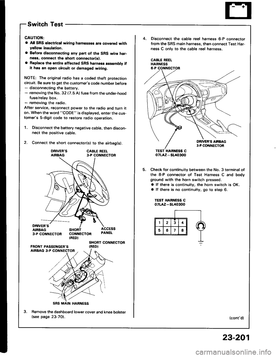
2. Connect the short connector(sl to the airbag(sl.
DRIVER'SAIRBAGCABLE REEL3.P CO NECTOR
DRIVER'SAIRBAG3-PCO'TNECTOR COI{NECTOR{RED}
ACCESSPAI{EL
SHORT CONTIECTOR{REO}
Remove the dashboatd lower cover and kne€(see page 23-701.
5.
4. Disconnect the cable reel harness 6-P connector
from the SRS main harness, then connect Test Har-
ness C onlv to the cable reel harness.
CABLE REELHARNESS
TEST HAR ESS CoTLAz - SL/l{,3OO
Check for continuity between the No, 3 terminal ot
the 8-P connector of Test Harness C and body
ground with the horn switch pressed.
a lf there is continuity, the horn switch is OK.a lf there is no continuity, go to step 6.
TEST HARNESS COTLAZ-SI/I()3OO
(cont'd)
bolster
23-201
Page 1352 of 1413

Cruise Control
Control Unit Input Test
CAUTION:
a All SRS olectrical wi ng harnessos are covored with
yellow insulation.
a Botore disconnecting any part of th6 SRS wire har-
neaa, connect the short connoctor(sl.
a Roplace the €ntir€ affectod SRS hamass assembly il
il has an opan circuit or damaged wifng.
1 , Remove the dashboard lower cover and knee bolster(see page 23-70).
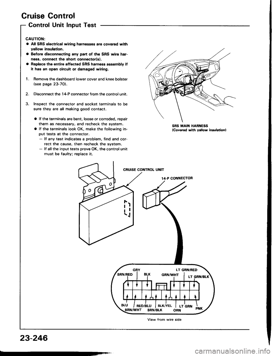
2. Disconnect the 14-P connector trom the control unit.
Insoect the connector and socket terminals to be
sure they are all making good contact.
a lf the terminals are bent, loose or corroded, repair
them as necessary, and recheck the system.
a It the terminals look OK, make the following in-
Dut tests at the connector.- It any test indicates a problem, find and cor-
rect the cause. then recheck the svstem.- lf allthe input tesls prove OK, the control unit
must be faulty; replace it.
CRUISE CONTROL UNIT
14-P COI{NECTOR
SRS MAIN HARNESS
23-246
Viow from wire side
Page 1354 of 1413

Cruise Gontrol
Set/Resume Switch Test/Replacement
CAUTION:
a All SRS ol6ct cal widng herne$a3 err covorod with
y6llow insulation.
a Bototo disconnecting any part ot tho SRS wiro h8r-
n6sa, connoct tho ghort connector(sl,
a Rsplaco the antire aftected SRS harness arsombly if
it has an op6n chcuit or damagod wiring.
NOTE: The original radio has a coded theft protection
circuit, Be sure to get the customer's code number befor€- disconnecting the battery.- removing the No. 32 (7.5 A) fuse from the under-hood
fuse/relay box.- removing the radio.
Afte, service, reconnect power to the radio and turn it
on. When the word "CODE" is displayed, enter the cus-
tomer's s-digit code to restore radio op€ration.
1 . Disconnect the battery negative cable, then discon-
nect the Dositive cable.
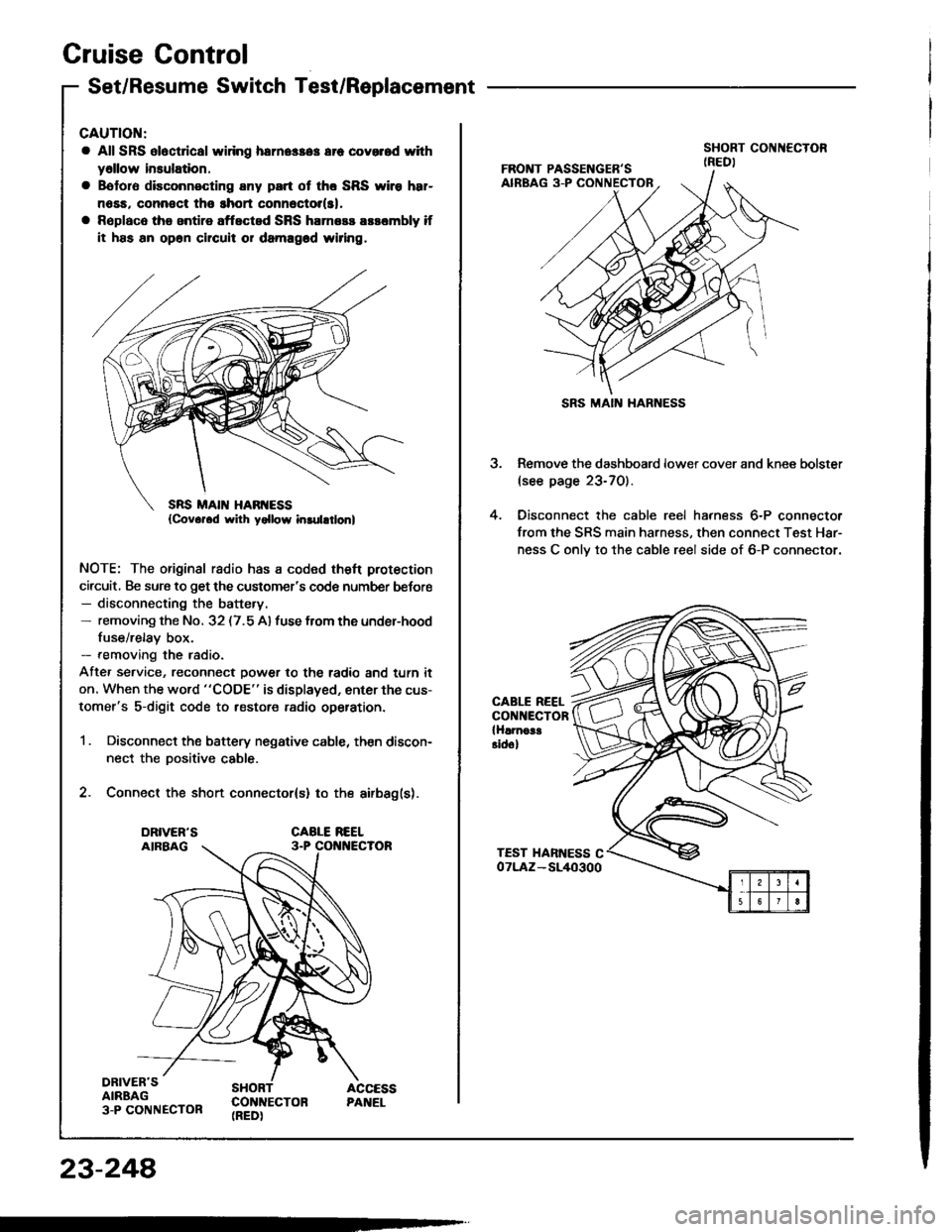
2. Connect the short connector(s) to the airbag(s).
DRIVER'SAIRBAG3-P CONNECTOR
SHORT ACCESSCON]TECTON PANEL(REDI
23-248
SRS MAIN HARNESS
3. Remove the dashboard lower cover and knee bolster(see page 23-70).
4. Oisconnect the cable reel harness 6-P connector
from the SRS main harness, then connect Test Har-
ness C onlv to the cable reel side of 6-P connector.
CABLE REELCONNECTORlHlrnoa!Eidol