Ignition harness HONDA INTEGRA 1994 4.G Owner's Manual
[x] Cancel search | Manufacturer: HONDA, Model Year: 1994, Model line: INTEGRA, Model: HONDA INTEGRA 1994 4.GPages: 1413, PDF Size: 37.94 MB
Page 299 of 1413
Fuel Supply System
Fuel Pump (cont'dl
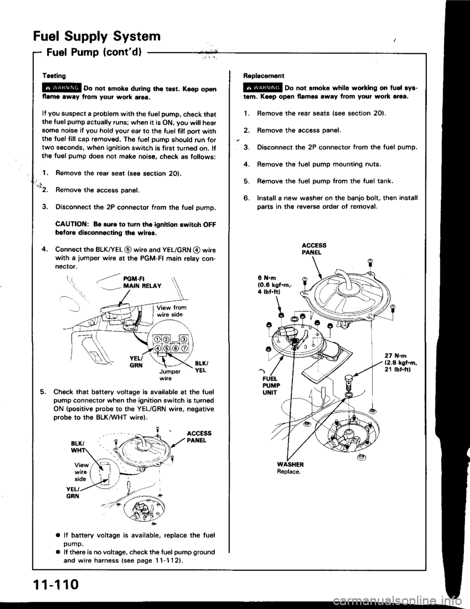
Tc.ting
@E o" not smoko during tho tesr. Koop openflrmo away fiom your work area.
lf you susp€ct a problem with the tuel pump, check thatthe lusl pump actually runs; when it is ON, you will hearsome noise if you hold your ear to the luel lill oon withthe fuel fill cap remov6d. The fuel pumD should run fortwo seconds, when ignition switch is first turned on. llthe fuel pump does not make noiss, check as tollows;
1. Removo the rear seat (see section 2O).
-'2. Remove the access panel.
3. Disconnect the 2P connector from the fuel pump.
CAUTION: 86 lure to tum th6 ignition switch OFFbotor6 disconnoctlng th€ wilos,
4. Connect the BLK|yEL @ wire 8nd YEL/GRN @ wirewith a iumpe. wire 8t the PGM-FI main relav con-
nectot.
l.t, .--/ re -Fl. . MAll{ RELAY
BL&YELJumper
Check that battery voltage is available at the tuel
pump connector when the ignition switch is turned
ON (positive probe to the YEL/GRN wire, negativeprobe to ths BLK/WHT wire).
ACCESSPANEL
side
YEL/GRN
a lf battery voltage is available, replace the fuel
pump.
a It there is no voltage, check the tusl pump ground
and wire harness {see page I 1-1 l2).
11-110
Roplacomont
@ oo not smoks whilo worklng on fuel syr-
tem. Kaop opon llamos away from your wolk araa.
1. Remove the rear ssats {soe section 2O).
2. Remove the access oanel.
3. Disconnect the 2P connector from the fuel pump.
4. Remove the fuel pump mounting nuts.
5. Remove the fuel pump trom the luel tank.
6. Install a new washer on the banio bolt, then install
Darts in the revers€ order of removal.
6 N.mlO.6 kgl.m,.4 tbt.ftl
27 .m(2.4 kgt.m,21 tbt.ftl
Page 302 of 1413
(From page 'l'l-1121
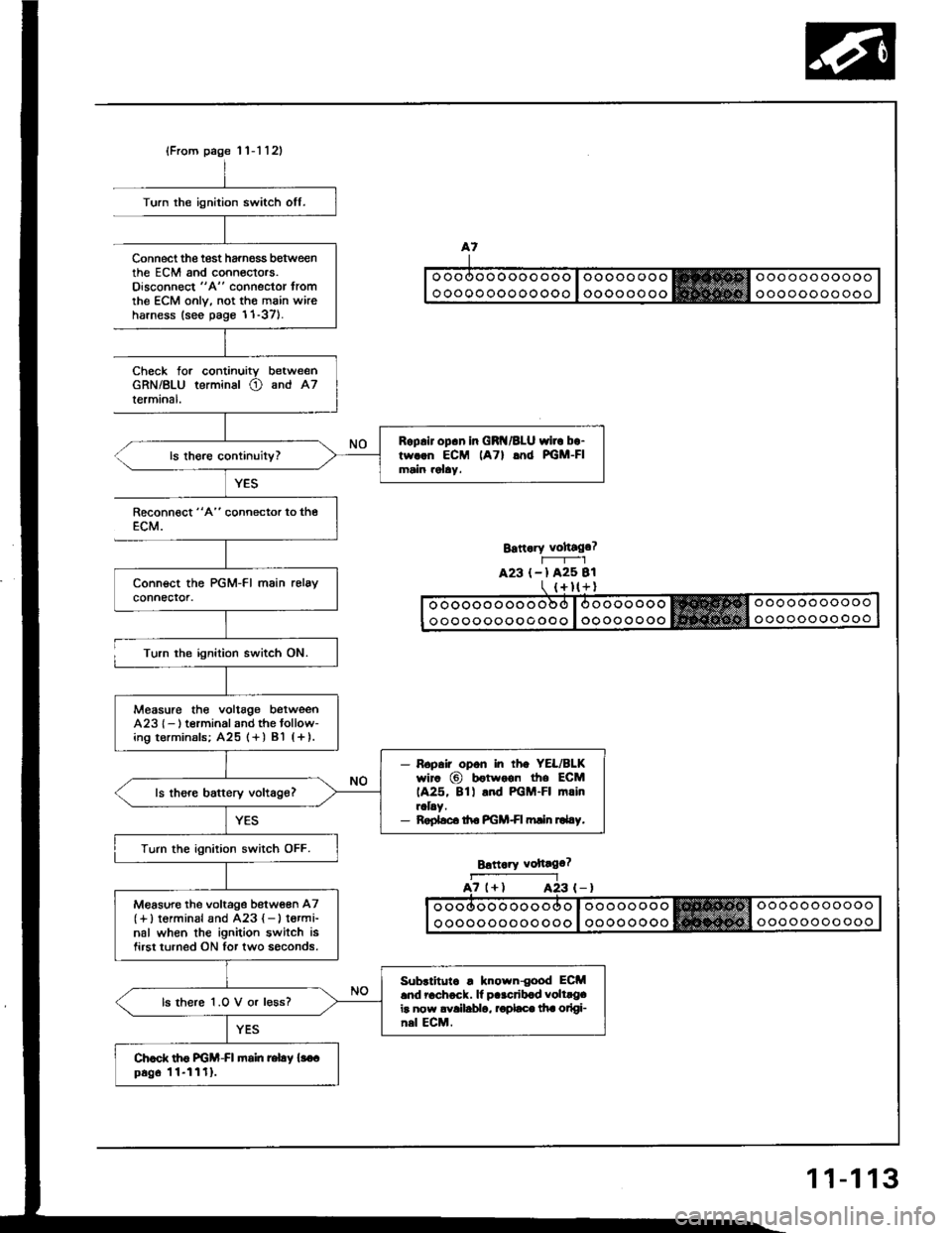
Roplir op.n in GRI{/BLU wirc bo-tw..n ECM lATl lnd PGM-FImain rolay.
Measure the voltag€ betweenA23l- ) t€rminal and the tollow-ing t€rminals; A25 (+ ) Bl (+ ).
- Ropair opon in rh. YEL/BLKwir. @ b€twoon the ECM1A25, 8tl .nd PGM-FI mrinraLy.- Roplsc. ttro PGM+I min ru4.y.
Turn the ignition switch OFF.
M€asure the voltage betw€en A7(+)torminal and A23 { - } t€rmi-nal when the ignition switch isfirst turned ON for two soconds.
Subrlitutc . known{ood ECM.nd 6chock. lf p..crib.d volt.g.ir now avallablo, rodaco lha otlgi-nsl ECM.
ls there 1.O V or l€ss?
Chod. th6 FGM-FI fioin relay {3o.p6g6 11-1111.
Turn the ignition switch off.
Connect the test harnoss b€tweenthe EcM and conneclors.Oisconnect "A" connector tromthe ECM onlv. not the main wireharness (see page 1'1-37).
Check forGRN/BLUlermrnal.
continuity betweenterminal O and A7
YES
Reconn€ct "4" connector to theECM.
Turn the ignition switch ON.
Bstt.ry vohago?r-----r_-lA23 (-l A25 Bl
Brttaiy voftago?
a7 (+l A23A23 (-)
11-113
Page 314 of 1413
(From page 1 1-124)
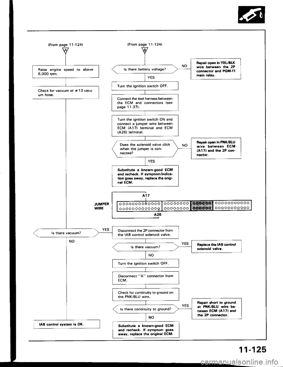
Raise engine speed to above6,000 rpm.
Disconnect the 2P connector tromthe IAB control solenoid valve.
Turn the ignition switch OFF.
Check for continuity to ground onthe PNK/BLU wire.
Ropair short to g.ound
at PNK/BLU wiro bo-two6n ECM {A17) andtho 2P connector.
ls there continuity to ground?
Substituto a known-good ECMand racheck. It symptom goos
swsy, roplace tho original ECM.
{From pago 1 1-124}
Repsir op6n in YEL/BLKwiro botwoon tho 2Pconnector and FGM-FImain relaY.
ls there battery voltage?
Turn the ignition swirch OFF.
Connect lhe test harness betweenthe ECM and connectors lseepage 11-37).
Turn the ignition switch ON andconnect a lumper wke betweenECM (A17) terminal and ECM
{A26) terminal.
Ropaiiopon inP K/BLUwiao botwoen ECM
lAl7l and tho 2P con-nectot.
Ooes the solenoid valve clickwhen the jumper is con-nected?
Sub3titute a known-good ECMand rechock. lf symptom/indica-tion goos away, r6place tho origi-nal ECM.
Check lor vacuum at #'l3 vacu-um hose.
IAB control syst6m is OK.
11-125
Page 441 of 1413
CAUTIOI{:
a All SRS eloctdcal wiring harna$os are covcred whh
yollow lnaulation.
a Sofora disconnecting any pan ot tho SRS wirc har'
n6ss, connoct the short connoctots (s€6 pago 23-701.
a Roplacs tho entiro aff.ct d SRS ham6t. rssombly it
ii has an opon circuil or damagcd wlrlng.
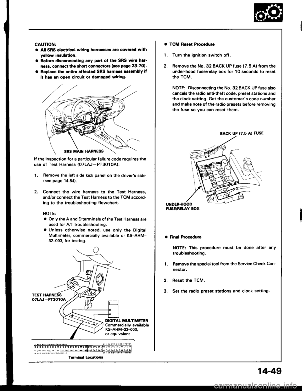
lf the inspection to. a particular lailure code requir6s the
use of Test Harness {07LAJ - PT3O1 OA):
1, Remove the left side kick panel on the driver's side(see page 1+84).
2. Connect the wire harness to the Tsst Harness.
and/or connect the Test Harness to the TCM sccord-
ing to the troubleshooting flowchart.
NOTE:
a Only the A and D terminals of the Test Harnsss aro
used for Ay'T troubleshooting.
a Unless otherwise noted, use only the Digital
Multimeter, commerciallv available or KS-AHM-
32{)03, for testing.
c
DIG]TAL MULTIMETERComm€rciallv availableKS-AH M-32-.003,or gouivalEnt
) o o o o o o o o o o ) olo D o o o o o qoo o o o olo o o o o . o o o . c
To.miml Locrtlonr
a TCM Ro3at Procoduro
1 . Tum the ignition switch off.
2. Remove the No. 32 BACK UP fuse {7.5 A} from the
under-hood luse/relay box 'or 10 seconds to reset
the TCM.
NOTE; Disconnocting the No. 32 BACK UP tuse also
cancels ths radio anti-theft code, preset stations and
tho clock sefting. Get the customer's code number
and make note ol the radio presets before removing
the fuss so you can reset them.
a Finll hoc.dulr
NOTE: This procedure must be done after any
troubleshooting.
1 . Removs ths s9ocialtool from the Service Check Con-
noctor.
2. Reset the TCM.
3, S6t th€ radio preset stations and clock setting.
BACK UP (7.5 A} FUSE
14-49
Page 444 of 1413
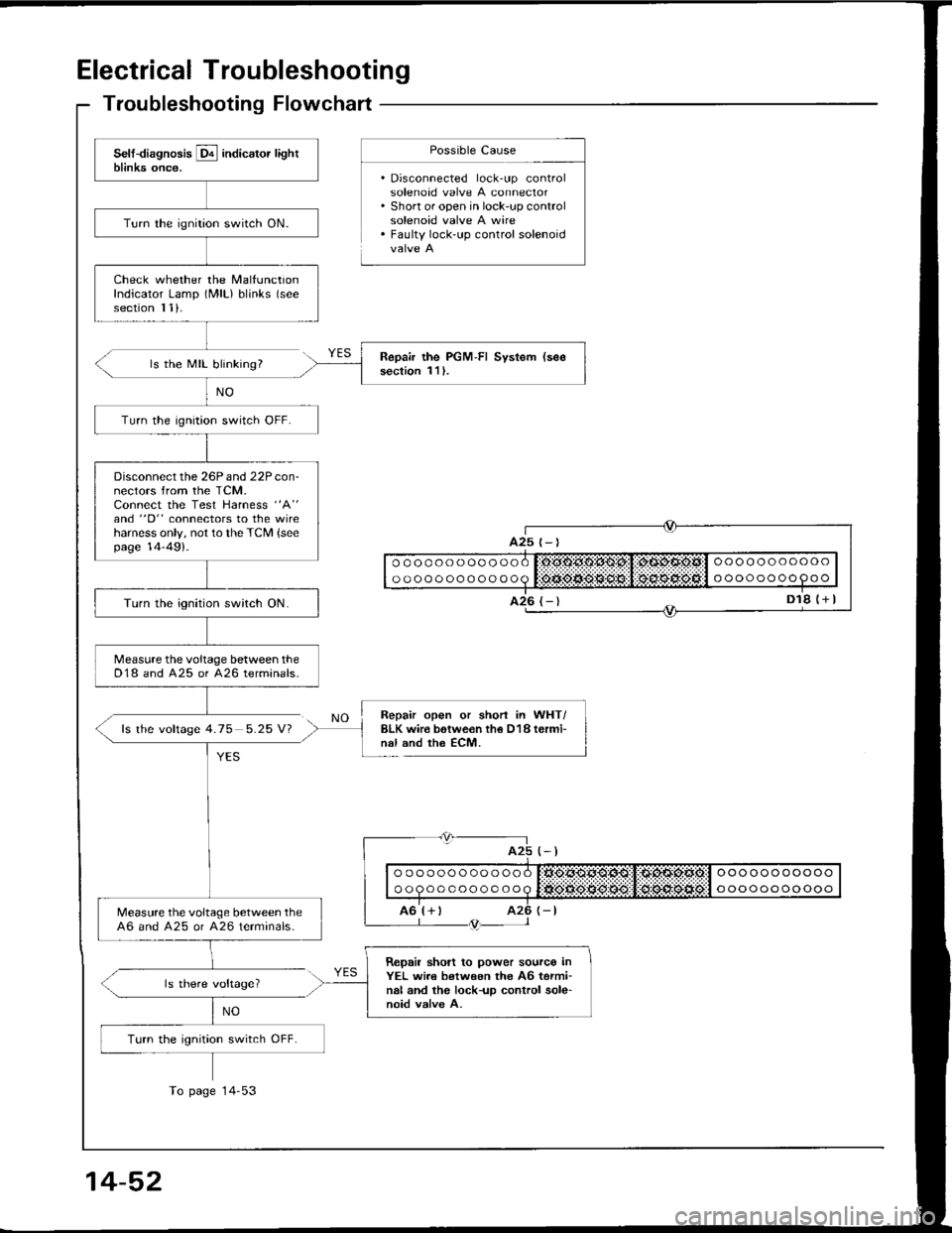
Electrical Troubleshooting
Troubleshooting Flowchart
ls the MIL blinking?
fs the voftage 4.75 5.25 V?
Possible Cause
. Disconnected lock-up controlsolenoad valve A connector. Short or open in lock-up controlsolenoid valve A wire. Faulty lock-up control solenoid
NO
YES
Repair open or shorl in WHT/BLK wir€ botwe€n th€ D18 termi-nal and the ECM.
(-)
| | o " q " " o o o o o o o q litigse.*grq$:,1:d:sd:siia:l " "" o " " o o oo " I
I ro'r+ r rz6 r-tL--- l /trtr-- l
ls there voltage?
NO
ooooooooooo
oooooooo9oo
oooooooooooo
oooooooooooo
A25
Turn the ignition switch ON.
Check whether the MalfunctionIndicator Lamp (MlL) blinks (see
section I 1).
Repair the PGM-FI System (see
section 1 l ).
Turn the ignition switch OFF.
Disconnect the 26P and 22P con-nectors from the TCM.Connect the Test Harness "A"
and "D" connectors to the wireharness only, not to the TCM {seepage 14-49).
Turn the ignition switch ON.
Measure the voltage between theD18 and A25 or 426 terminals.
Measure the voltage between the46 and A25 or A26 terminals-
Repail short to power sourco inYEL wi.e between the A6 termi-nal and the lock-up control sole-noid valve A.
Turn the ignition switch OFF.
To page 14'53
14-52
Page 446 of 1413
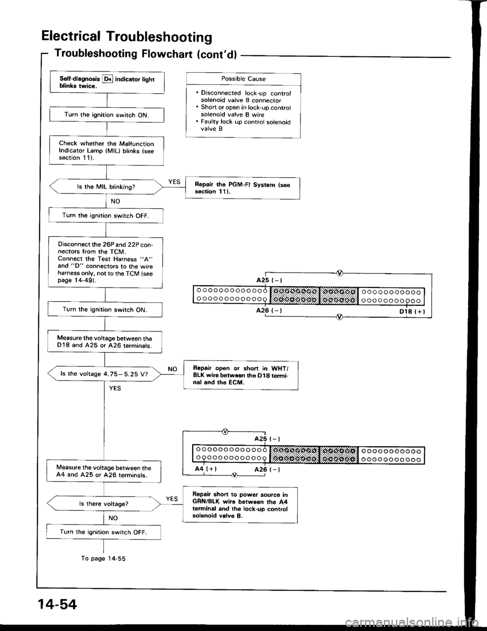
Electrical Troubleshooting
Troubleshooting Flowchart (cont'dl
Turn the ignition switch ON.
Check whether the MalfunctionIndicator Lamp (MlL) blinks (seesection 1 1).
Ropair tho PGM-FI Sysrom (se€soction 11).ls the MIL blinking?
Turn the ignition switch OFF.
Disconnect the 26P and 22P con-nectors trom the TCM.Connect the Test Harness "A"
and "D" connecto.s lo the wireharness only, not to the TCM (seepage 14-49).
Turn the ignition switch ON.
Measure the voltage between theD'18 and A25 or 426 terminats_
Rapair opon or shon in WHT/BLK wi.e botweon the O18 te.mi-nal rnd the ECM.
ls the voltage 4.75-5.25 V?
lvleasure the voltage between the44 and A25 or 426 rerminals.
Ropsir shon to power source inGRN/BLK wi.o betwoon the A4t6.minal and th€ lock-up controlsolonoid valve B.
Turn the ignition switch OFF.
14-54
Possible Cause
. Disconnected lock-up conlrolsolenoid valve B connector. Short or open in lock-up controlsolenoid valve B wire. Faulty lock up control solenoidvalve B
Page 448 of 1413
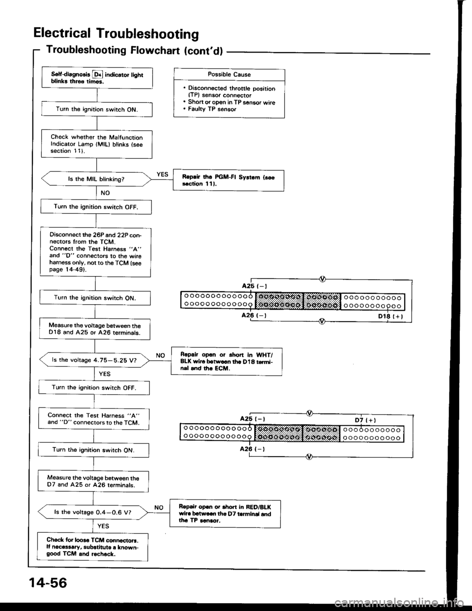
Troubleshooting Flowchart (cont'd)
Sof{irgnolis D! indic€tor tightblinks throo rim6s.
Turn the ignition switch ON.
Check whother the MalfunctionIndicator Lamp (MlL) blinks (seesection 1 1).
Replir thc PGM-FI Syrtom l.s.!.ction 111.ls the MIL blinking?
Turn the ignition switch OFF.
Oisconnect rho 26P 6nd 22P con-nectors lrom the TCM.Connect the Test Harness "A"
and "D" connectors to the wireharness only, not to the TCM lseepage |4-491.
Turn the ignition switch ON.
Measure the voltage between theDl8 and A25 or A26 teiminats.
Rcpalr opon or shon In WHT/BLK wlr. botw.cn th. D18 t.mi-nsl rnd th. ECM.
ls the voltage 4.75-5.25 V?
Turn the ignirion swirch OFF.
Connect the Test Harness "A"
and "D" connectors to the TCM.
Turn the ignition switch ON.
Measure the voltage betwe€n theD7 and A25 or 426 rerminals.
Roprlr oprn o. lhon in RED/BLKwil. botwaan tha DT ta]minal andtha TP ranaor.
ls the voltage 0.4-0.6 V?
Chock tor looro TCM connoctora.ll noce$rry, subatitulo r known-good TCM and rechock.
Possible Cause
. Disconnocted throttle position{TP) sensoa connoctor. Short or oDen in TP s€nsor wire. Faulty TP senaor
Page 450 of 1413
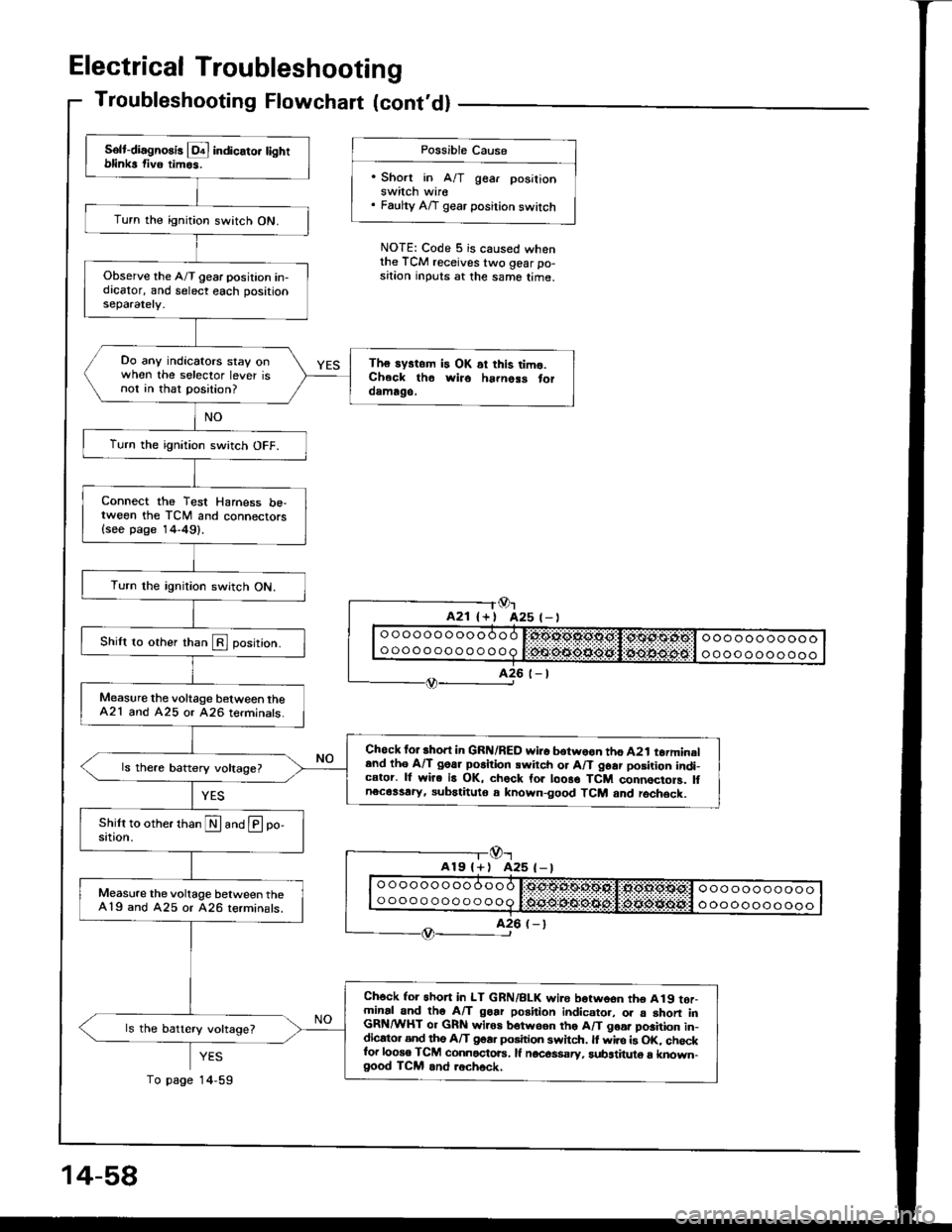
Electrical Troubleshooting
Troubleshooting Flowchart lcont'dl
Possible Cause
'Short in A/T gear posilionswitch wire. Faulty A/T gear position switch
NOTE: Code 5 is caused whenthe TCM receives two gear po-sition inputs at the same time.
Or425 t- |
-l@r
A19l+) A25 (-)
YES
14,59
Solt-diagno8is l!4 indicato. tightblinks fiv6 timos.
Turn the ignition switch ON.
Observe the A/T gear position in-dicator, and select each positionseparately.
Do any indicators stay onwhen the selector lever isnot in that position?
The systom is OK ai this timo.Ch.ck tho wiro ha|noss toroamago.
Turn the ignition switch OFF.
Connect the Test Harness be,tween the TCM and connectors{see page 14-49}.
Turn the rgnition switch ON.
Shilt to other than E position.
Measure the voltage b€tween theA21 and A25 or 426 terminats.
Chock for short in GRN/RED wi.o botwoon tho A2t torminaland th6 A/T goar po6ition swirch or A/T 96ar posirion indi-cator. lf wire is OK, chock for loo8o TCM connocioF. lfnecassary, subatituto a known-good TCM and rochsck.
Measure the voltage between the419 and A25 or 426 terminals.
Ch6ck for 6hon in LT GRN/BLK wi.e borwoon tho A19 tor-minal and tho A/T goar position indicato., o. a shon inGRN/WHT or GRN wiros botwson tho A/T goa. position in-dicato. and tho A/T goa. position swhch. ll wire is OK. chockfor looso TCM connactoE. lf nocos$sry, substituto a known-good TCM and .ech6ck,
ls the battery voltage?
14-58
To page
Page 452 of 1413
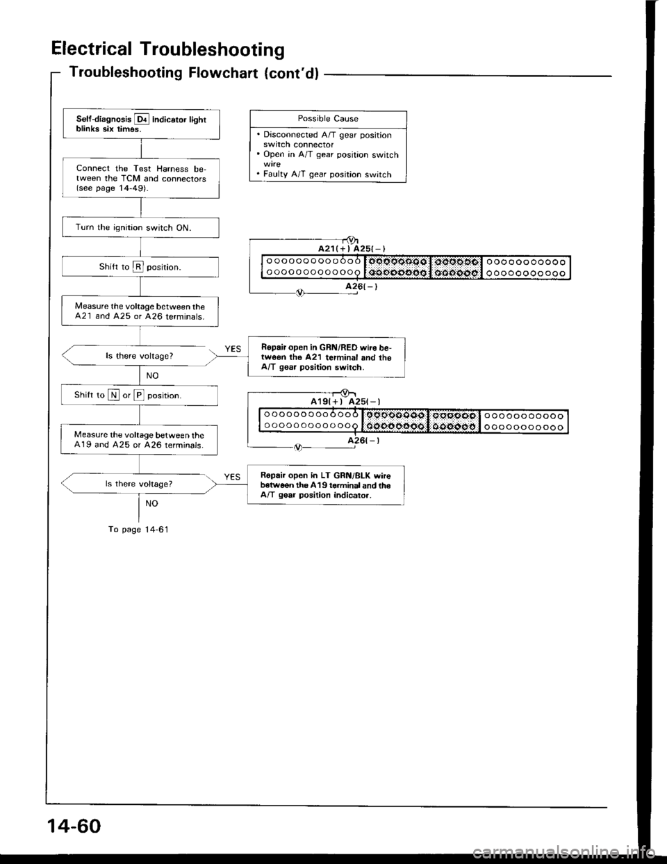
Electrical Troubleshooting
Troubleshooting Flowchart {cont'dl
ls there voltage?
ls there voltage?
NO
To page l4-61
- - r9ta21(+ I A25{-)
Self-diagnosis E indicator lightblinka six timos.
Connect the Test Harness be,tween the TCM and connectors(see page '14-49).
Turn the ignition switch ON.
Measure the voltage between theA21 and 425 or 426 terminals.
Ropair open in GRN/RED wire be,tweon th6 A21 terminal and theA/T gssr position switch.
Shilt ro N or E position.
Measure the voltage between theA19 and A25 or A26 terminals.
Ropair open in LT GRN/BLK wireb€tw6on the 419 torminal and th€A/T gear position indicato..
Possible Cause
. Disconnected A/T gear positionswrtcn connector' Open in A/T gear position switch
. Faulty A/T gear position switch
oooooooooooo
ooooooooooooooooooooooo
ooooooooooo
A25t-l
oooooooooooo
ooooooooooooooooooooooo
ooooooooooo
14-60
Page 454 of 1413
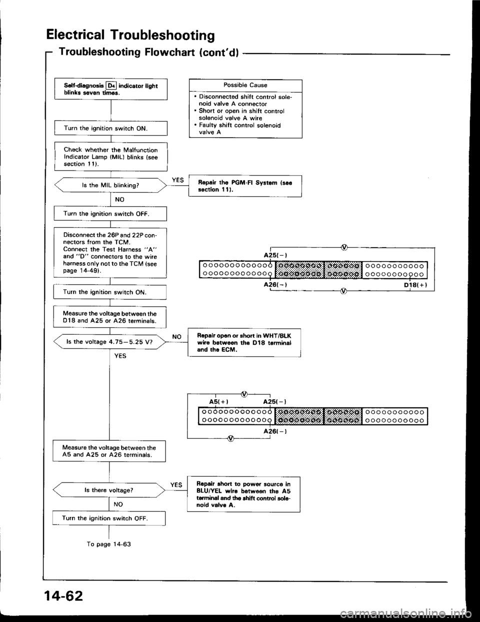
Electrical Troubleshooting
S€ltdiagno3b Lql indicaror lighrblinks sovon timgs.
Turn the ignition switch ON.
Check whether the MalfunctionIndicator Lamp {MlL) blinks (seesection 11).
Ropai lhe PGM-FI Sysrem (so€Bection 1 11,ls the MIL blinking?
Turn th6 ignition switch OFF.
Disconnect the 26P and22P con-nectors from the TCM.Connect the Test Harness "A"
and "D" connectors to the wireharness only not to the TCM (seepage 14-49).
Turn the ignition switch ON.
Measure the voltage betw€€n theD18 and A25 or A26 lerminals.
Repair opon o. sho.t in WHT/BLKwire botwoon th€ D18 tarminaland the ECM.
fs the voftage 4.75-5.25 V?
Measure the voltage between theA5 and A25 or A26 terminals.
Ropair lhon to powor sourc6 inBLU/YEL wiro botwoon the A5torminal and th6 lhift control solo-noid valve A.
Turn the ignition switch OFF.
Troubleshooting Flowchart (cont'dl
Dl8( r I
Possible Cause
. Discohnected shift control sole-noid valve A connector. Short or open in shift controlsolenoid valve A wire. Faulty shill control solenoid
ooooooooooooooooooooooo
ooooo oooooooa t:tJio*ie*O:lt$!l $4lrulitEijt'l o oo oooooooo