main fuse HONDA INTEGRA 1994 4.G Owner's Manual
[x] Cancel search | Manufacturer: HONDA, Model Year: 1994, Model line: INTEGRA, Model: HONDA INTEGRA 1994 4.GPages: 1413, PDF Size: 37.94 MB
Page 1136 of 1413
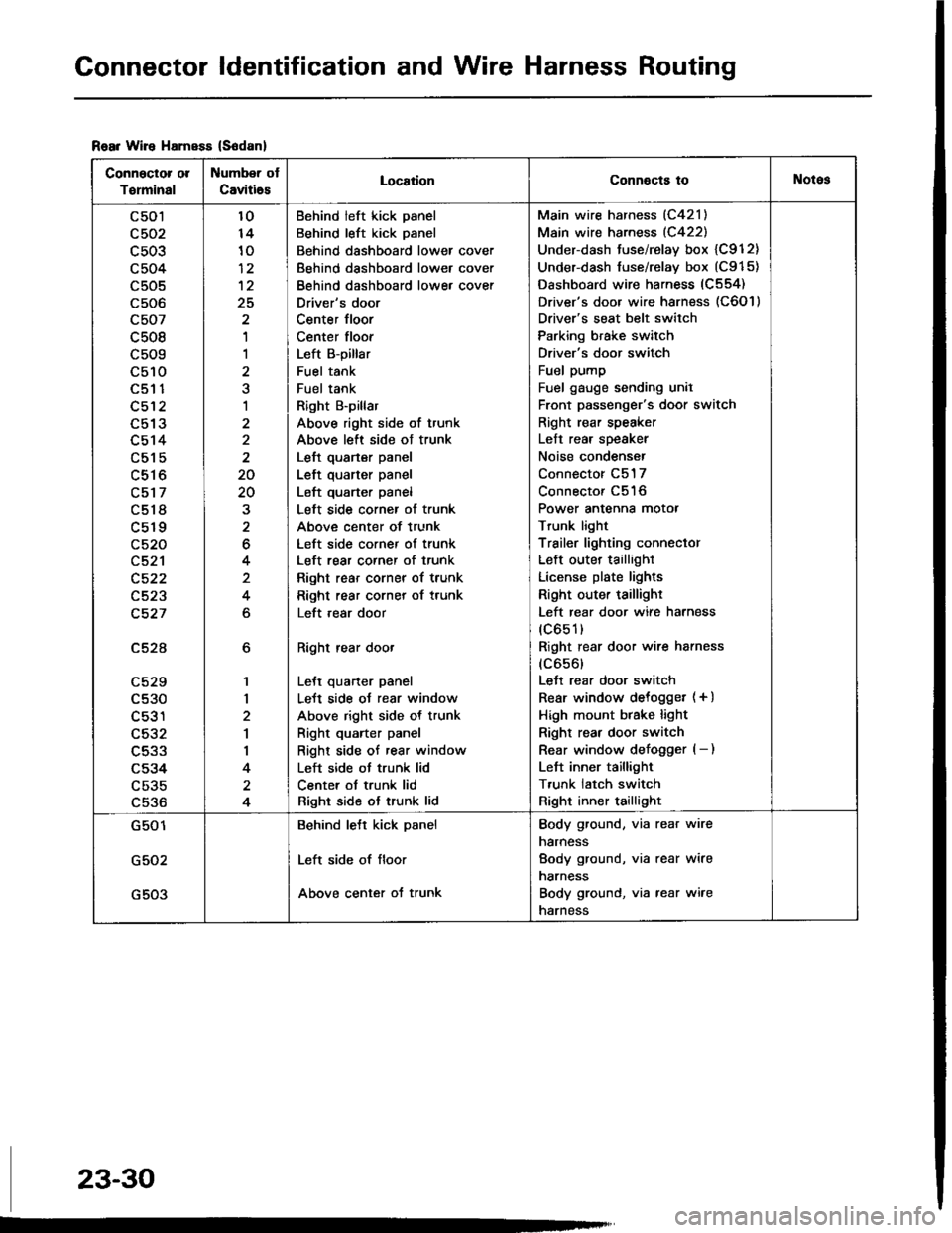
Connector ldentification and Wire Harness Routing
Rear Wire HamsEs (S6danl
Connector ol
Torminal
Number ot
Caviti6sLocaiionConnocts toNotos
c501
c503
c504
c505
c506
c507
c508
c509
c510aEt t
c512
L9 IJ
c514
c515
c516
c517
c518
c519
c520
c521
c522
c523
c527
c52A
LCZY
c530
c531
c532
c533
c534
c535
c536
6
1,|
2
1
I
4
4
10
10
12
25
'I
1
a
1
2
2
20
20
2
6
4
4
6
Behind left kick panel
Behind left kick panel
Behind dashboard lower cover
Behind dashboard lower cover
Behind dashboard lowe, cover
Driver's door
Center floor
Center floor
Left B-pillar
Fuel tank
Fuel tank
Right B'pillar
Above right side of trunk
Above left side ot trunk
Left quarter panel
Left quarter panel
Left quarter panel
Left side corner of trunk
Above center of trunk
Left side corner of trunk
Left rear corner of trunk
Right rear corner of trunk
Right rear corner of trunk
Left ,ear door
Right rear door
LeJt quarter panel
LeJt side oJ rear window
Above right side of trunk
Right quarter panel
Right side of rear window
Left side ot trunk lid
Center ot trunk lid
Right side ot trunk lid
Main wire harness (C421)
Main wire harness (C422)
Under-dash tuse/relay box {C912}
Under-dash fuse/relay box (C915)
Dashboard wire harness (C554)
Driver's door wire harness (C6O l )
Driver's seat belt switch
Parking brake switch
Driver's door switch
Fuel pump
Fuel gauge sending unil
Front passenger's door switch
Right rear speaker
Left rear speaker
Noise condenser
Connector C517
Connector C516
Power antenna motor
Trunk light
Trailer lighting conneclor
Left outer taillighr
License plate lights
Right outer taillighr
Left rear door wire harness
(c651)
Right rear door wire harness
(c656)
Lett rear door switch
Rear window delogget (+ )
High mount btake light
Right rear door switch
Rear window defogger (- )
Left inner taillight
T,unk latch switch
Right inner taillight
G501
G502
G503
Behind lett kick panel
Left side of floor
Above center of trunk
Body ground, via rear wire
narness
Body ground, via rear wire
narness
Body ground, via rear wire
narness
23-30
Page 1138 of 1413
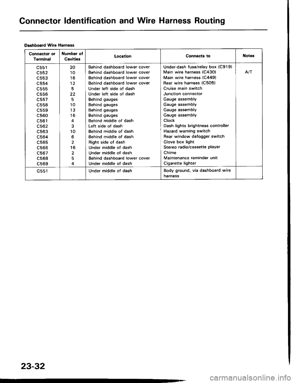
Connector ldentification and Wire Harness Routing
Dashboard wile Ha.n6ss
Connector ot
T€rminal
Number of
Caviti6sLocationConnects toNotes
c553
c554
L55b
c556
c557
c558
c560
LCO I
c563
c564
c565
c566
c567
c568a 6ACl
20
10
to
12
5
22
10
13
16
10
6
to
2
Behind dashboard lower cover
Behind dashboard lower cover
Behind dashboard lower cover
Behind dashboard lower cover
Under lett side oJ dash
Under left side of dash
Behind gauges
Behind gauges
Behind gauges
Behind gauges
Behind middle of dash
Left side of dash
Behind middle of dash
Behind middle of dash
Right side of dash
Under middle of dash
Under middle of dash
Behind dashboard lower cover
Under middle of dash
Under-dash fuse/relay box (C919)
Main wire harness (C43Ol
Main wire harness (C4491
Rear wire harness {C505)
Cruise main switch
Junction connector
Gauge assembly
Gauge assembly
Gauge assembly
Gauge assembly
Clock
Dash lights brightness controller
Hazard warning switch
Rear window defogger switch
Glov€ box light
Stereo radio/cassette PlaYer
Chime
Maintenance reminde. unit
Cigarette lighter
Afi
Under middle of dashBody ground, via dashboard wire
harness
23-32
Page 1146 of 1413
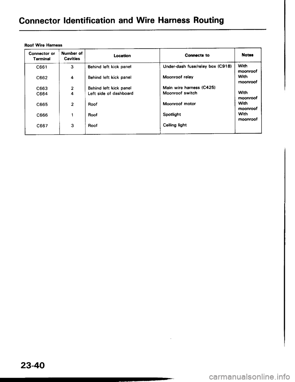
Gonnector ldentification and Wire Harness Routing
Roof Wire HanesE
Connector ol
Terminal
Number ot
CavitissLocationConnccts toNotct
c661
c662
LOOJ
c664
LOO5
LOOO
c667
4
4
2
I
Behind left kick panel
Behind left kick panel
Behind left kick panel
Left side of dashboa.d
Roof
Roof
Roof
Under-dash fuse/relay box (C918)
Moonroot relay
Main wire harnoss (C425)
Moonroof switch
Moonroof motor
Spotlight
Ceiling light
with
moonroof
with
moonroof
with
moonroof
with
moonroot
with
moonroot
23-40
Page 1153 of 1413
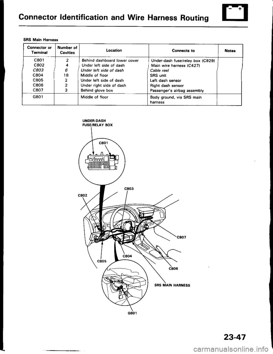
Connector ldentification and Wire Harness Routing
UNDER-DASHFUSE/RELAY BOX
SRS Main Harness
Connector or
Terminal
Number ol
CavitiesLocationConnocts tol{otos
c801
c802
c803
c804
c805
c806
c807
2
4
o
18
2
I Behind dashboard lowet cover
J Under left side of dash
Under left side of dash
Middle of floor
Under left side of dash
Under right side of dash
Behind glove box
Under-dash f use/rclay box (C929)
Main wire haness 1C427)
Cable reel
SRS unit
Left dash sensor
Right dash sensor
Passenger's airbag assembly
G801Middle of floorBody ground, via SRS main
harness
23-47
Page 1154 of 1413
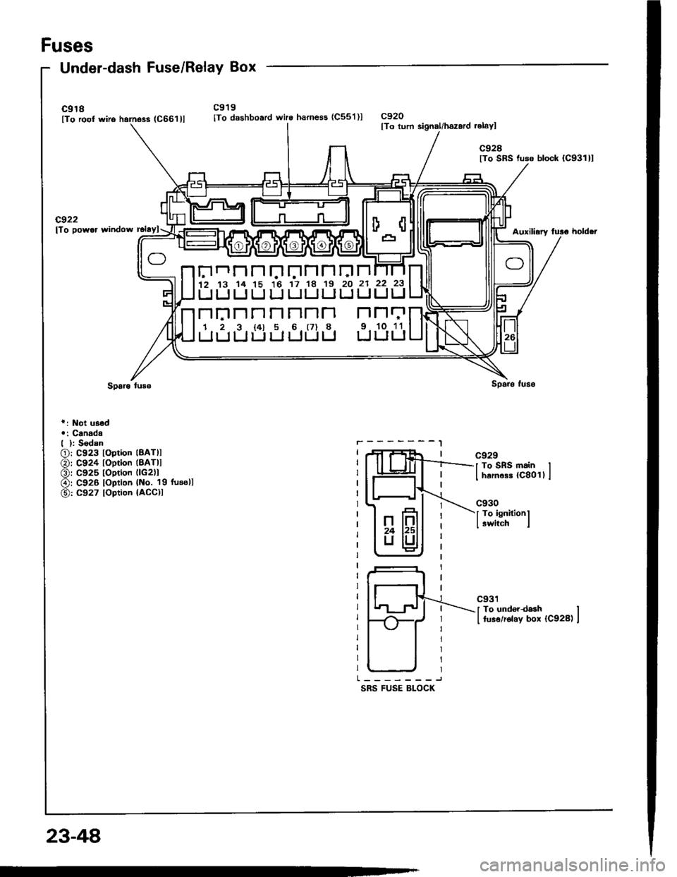
Fuses
Under-dash Fuse/Relay Box
c918lTo root wiro harness (C661llc919
lTo dashboard wire harness (C55'l )lc920lTo lurn signal/hszard .elayl
c928lTo SRS luso block {C931}l
cg22lTo powor window rclaylAuxili.ry fulo holdei
r: Not usod.: Canadd| ): S6dan
O: C923 loplion lBATll
@: C924 toption (BATll
O: C925 toption llc2)1
@r C926 loption {No. 19 fusoll
@: C927 loption {ACC)I
r.-------l
SRS FUSE BLOCK
c929
J To SRS main II harnass {C8011 I
c930
I To ignitionl
I switch i
c931
I To und€rdash II fuso/rolay box {C928) I
Elnnnr.'trJnnrJn12 13 14 15 16 17 18 19 20 21
UUIJUIJULJLILIIJ
n|:]nnnnnn r''l
1 2 3 t4l 5 6 (7) 8 9.
LIIJLIULJUUU U
22 23
UIJ
N11
10 11
LILI
23-48
Page 1155 of 1413
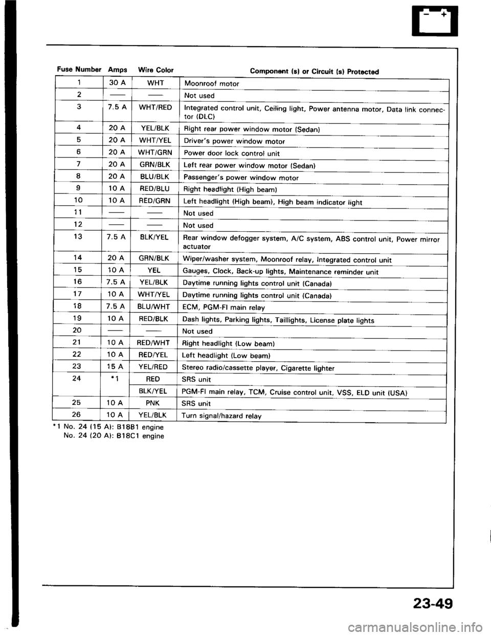
Fuse Numb€r AmDs Wire CololGomponent ls) or Circuit (s) Prot8cted
130AWHTMoonroof motor
2Not used
37.5 AWHT/REDIntegrated control unit, Ceiling light, Power antenna motor. Data link connec-tor (DLC)
420AYEL/BLKRight rea. power window motor (Sedan)
520AWHT/YELDriver's power window motor
o20AWHT/GRNPower door lock control unit
720AGRNiBLKLelt rear power window motor (Sedan)
I20ABLU/BLKPassenger's power window motor
I10 ARED/BLURight headlight {High beaml
1010 ARED/GRNLeft headlight (High beam). High beam indicato. tight
11Not used
12Not used
137.5 ABLK/YELRear window defogger system, A/C system, ABS control unit, power mrrroractuator
1420AGRN/BLKWiper/washer system, Moonroof relay, Integrated control unii'1510 AYELGauges, Clock, Back-up lights, Maintenance reminder unit
to7.5 AYEL/BLKDaytime running lights control unit (Canadal
1710 AWHT/YELDaytime running lights control unit (Csnada)
7.5 ABLU^tvHTECM, PGM-FI main relay'to10 ARED/BLKDash lights, Parking lights, Taillights, License plate tights
20Not used
2110 ARED/WHTRight headlight (Low beam)
10 ARED/YELLeft headlight (Low beam)
2315 AYEL/REDStereo radio/cassette player, Cigarette lighter
24REOSRS unit
BLK/YELPGM-FI main relay, TCM, Cruise controt unit, VSS, ELO unit IUSA)
2510 APNKSRS unit
2610 AYEL/BLKTurn signal/hazard relay'1 No.
No.
24 115 Al:
24 t2O At:.
81881 engine
B18Cl engine
23-49
Page 1157 of 1413
![HONDA INTEGRA 1994 4.G Owners Manual Under-hood ABS Fuse/Relay Box
Wire Color
C9O3 ITo ABS pump molor rolayl
C9O1 [To main wiro ham6$ (C212]l
Componont (s) or Circuit (sl Protectsd
T5 [To undo]-hood ABS fuso/rolay box cabl.l
C9O2 [To moi HONDA INTEGRA 1994 4.G Owners Manual Under-hood ABS Fuse/Relay Box
Wire Color
C9O3 ITo ABS pump molor rolayl
C9O1 [To main wiro ham6$ (C212]l
Componont (s) or Circuit (sl Protectsd
T5 [To undo]-hood ABS fuso/rolay box cabl.l
C9O2 [To moi](/img/13/6067/w960_6067-1156.png)
Under-hood ABS Fuse/Relay Box
Wire Color
C9O3 ITo ABS pump molor rolayl
C9O1 [To main wiro ham6$ (C212]l
Componont (s) or Circuit (sl Protectsd
T5 [To undo]-hood ABS fuso/rolay box cabl.l
C9O2 [To moin wiro hs1n6ss (C213]l
ABS 8120AWHT/GRNRight/left ABS front solenoids
ABS 8215 AWHTABS control unit, ABS rear solenoid
ABS MOTOR40AABS pump motor relay, ABS unit (10 A) fuse
ABS UNIT10 ABRN/YELABS control unit
23-51
Page 1158 of 1413
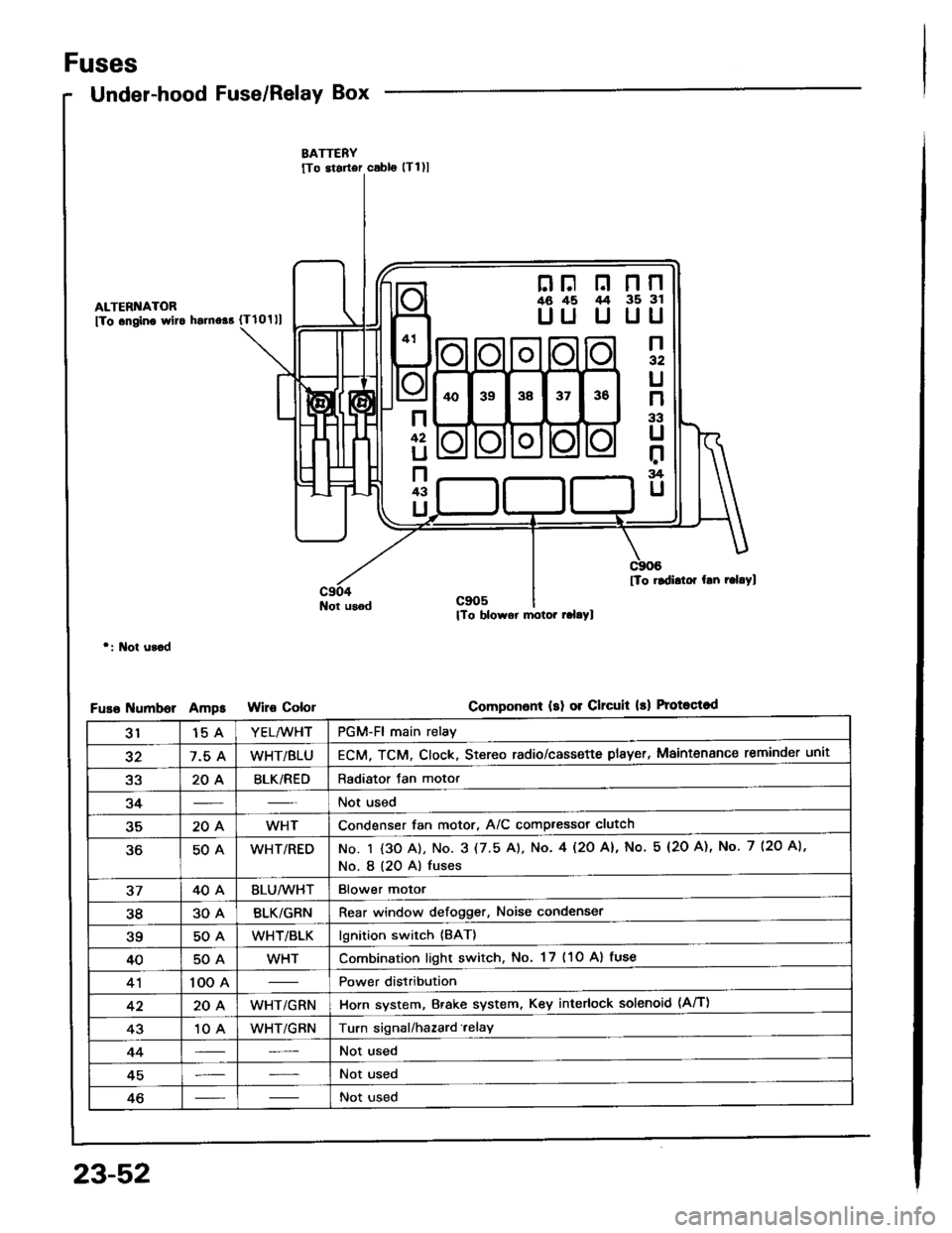
Fuses
Under-hood Fuse/Relay Box
ALTERI{ATOR
fTo .ngino wlto hsrno$ {Tlolll
Not usod
r: l\lot u3.d
umborAmpsColor
nF n nn46 45 /t4 35 3l
UU U UU
n32
U
n
33
U
r:rg
U
n
42
U
n43
U
[To rldidor hn r.l.Yl
Componon! (sl 01 Clrcuit 13) Protoqtod
3115 AYEL/WHTPGM-Fl main relay
327.5 AWHT/BLUECM, TCM. Clock, Stereo radio/cassette plsyer, Maintenance reminder unit
a2204BLK/REDRadiator Jan motor
34Not used
35204WHTCondenser fan motor, A/C compressor clutch
50AWHT/REDNo. I {3O A), No. 3 (7.5 A). No. 4l2O Al, No 5 (2O A), No. 7 (2O A),
No. I (20 A) fuses
3740ABLU/lVHTBlower motor
3830ABLK/GRNRear window defogger, Noise condenser
?q50AWHT/BLKlgnition switch {BAT}
4050AWHTCombination light switch, No. 17 (1O Al fuse
41100 APower distribution
4220AWHT/GRNHorn system, Brake system, Key interlock solenoid (Aff)
4310 AWHT/GRNTurn signal/hazard.elay
44Not used
45Not used
46Not used
23-52
Page 1176 of 1413
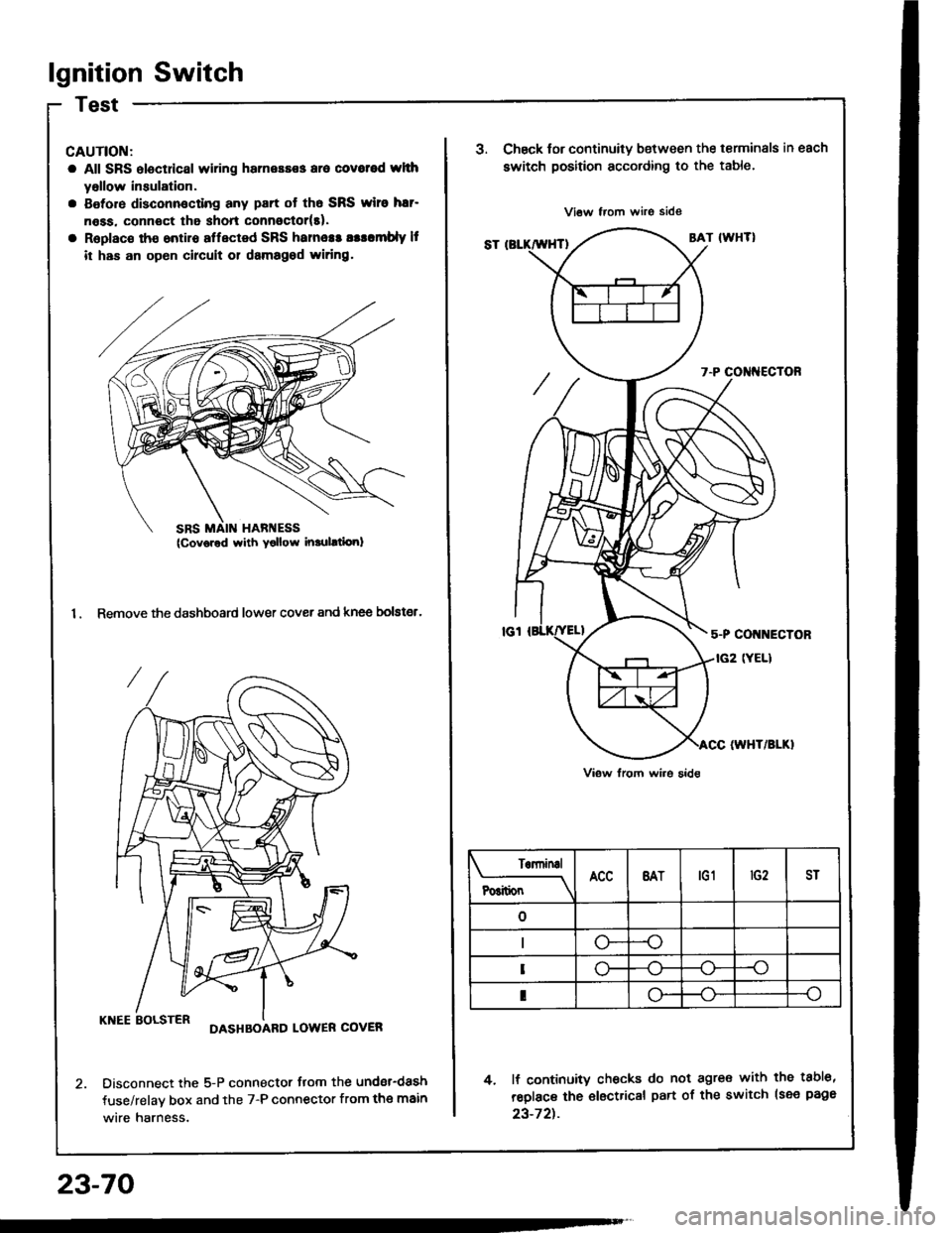
lgnition Switch
CAUTION:
a All SRS electdcal wiring harnessss aro covotod whh
yollow insulation.
a Botore disconnocting any part ot th6 SRS wiro har-
n6ss. connoct tha shon connoctor(t).
a Replac€ tho ontiro affected SRS hames! asllmbly It
it has an op6n circuit 01 damagod widng.
1. Remove the dashboard lower cover and knee bolster.
KNEE BOLSTERDASHBOARD LOWER COVER
Disconnect the 5-P connector flom the undsr-dash
fuse/relav box and the 7-P connector from the main
wire harness.
23-70
SRS MAIN HARI{ESS(Cov6red with Yollow inrulltiori)
J.Chsck tor continuity b€tween the terminals in each
switch position according to the table.
4. lf continuity checks do not agre€ with the tabl6,
reolace the €lectrical part of the switch lsee page
23-72t.
Terninal
P6itionBATtG1ST
--o
o-
I
Page 1177 of 1413
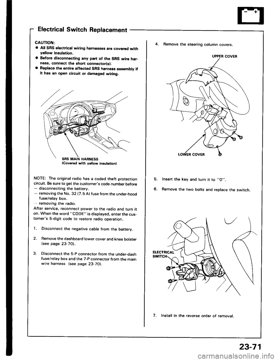
Electrical Switch Replacement
a All SRS €lectric8l wiring hamosses ar€ covorsd withyellow insulation,
a Befora disconnecting any pan of tho SRS wilo har-neas. connect the short connoctor(sl.a R6place the entire attect6d SFS harness assombly ifit has an opon circuit 01 damaged wiling.
NOTE: The original radio has a coded theft protection
circuit, Be sure to get the customer's code number before- disconnecting the battery.- removing the No. 32 (7.5 Al fuse from the under-hoodluse/relay box.- removang the radio.
After service, reconnect power to the radio and turn iton. When the word "CODE" is displayed, enter the cus-tomer's 5-digit code to restore radio ope.ation.
1. Disconnect the negative cable from the batery.
2. Remove the dashboard lower cover and knee bolster
{see page 23-70).
3. Disconnect the 5-P connector from the under-dashfuse/relay box and the 7-P connector from the mainwire harness (see page 23-70).
E
4. Remove the steering column covers.
Insert the key and turn it to ,,O',.
Remove the two bolts and replace the switch.
UPPER COVER
7. Install in the reve.se orde. of removat.
23-71