under dash harness HONDA INTEGRA 1994 4.G Owner's Manual
[x] Cancel search | Manufacturer: HONDA, Model Year: 1994, Model line: INTEGRA, Model: HONDA INTEGRA 1994 4.GPages: 1413, PDF Size: 37.94 MB
Page 1154 of 1413
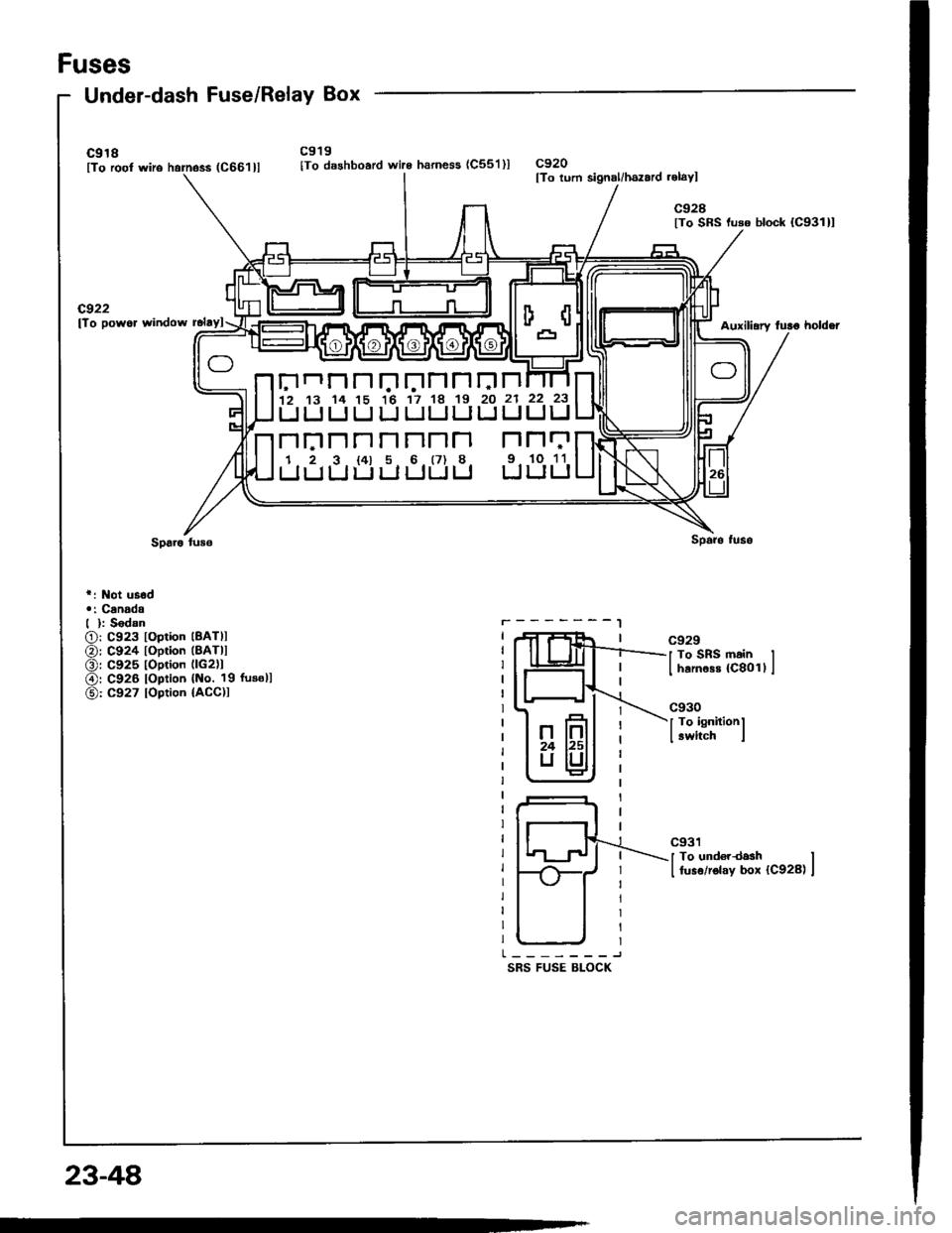
Fuses
Under-dash Fuse/Relay Box
c918lTo root wiro harness (C661llc919
lTo dashboard wire harness (C55'l )lc920lTo lurn signal/hszard .elayl
c928lTo SRS luso block {C931}l
cg22lTo powor window rclaylAuxili.ry fulo holdei
r: Not usod.: Canadd| ): S6dan
O: C923 loplion lBATll
@: C924 toption (BATll
O: C925 toption llc2)1
@r C926 loption {No. 19 fusoll
@: C927 loption {ACC)I
r.-------l
SRS FUSE BLOCK
c929
J To SRS main II harnass {C8011 I
c930
I To ignitionl
I switch i
c931
I To und€rdash II fuso/rolay box {C928) I
Elnnnr.'trJnnrJn12 13 14 15 16 17 18 19 20 21
UUIJUIJULJLILIIJ
n|:]nnnnnn r''l
1 2 3 t4l 5 6 (7) 8 9.
LIIJLIULJUUU U
22 23
UIJ
N11
10 11
LILI
23-48
Page 1177 of 1413
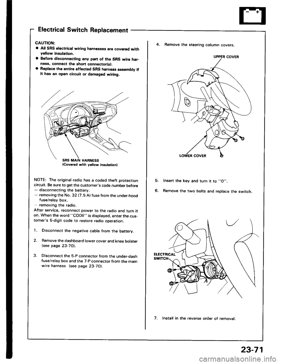
Electrical Switch Replacement
a All SRS €lectric8l wiring hamosses ar€ covorsd withyellow insulation,
a Befora disconnecting any pan of tho SRS wilo har-neas. connect the short connoctor(sl.a R6place the entire attect6d SFS harness assombly ifit has an opon circuit 01 damaged wiling.
NOTE: The original radio has a coded theft protection
circuit, Be sure to get the customer's code number before- disconnecting the battery.- removing the No. 32 (7.5 Al fuse from the under-hoodluse/relay box.- removang the radio.
After service, reconnect power to the radio and turn iton. When the word "CODE" is displayed, enter the cus-tomer's 5-digit code to restore radio ope.ation.
1. Disconnect the negative cable from the batery.
2. Remove the dashboard lower cover and knee bolster
{see page 23-70).
3. Disconnect the 5-P connector from the under-dashfuse/relay box and the 7-P connector from the mainwire harness (see page 23-70).
E
4. Remove the steering column covers.
Insert the key and turn it to ,,O',.
Remove the two bolts and replace the switch.
UPPER COVER
7. Install in the reve.se orde. of removat.
23-71
Page 1178 of 1413
lgnition Switch
Steering Lock Replacement
CAUTION:
a All SRS electrical wiring harnesses ale covsred with
yellow insulation.
a Belore disconnecting any parl ot the SRS wir€ hal-
ness, connecl the short connector{s).
a Replace the entire alfected SRS harness a$6mbly il
it has an open circuit or damaged wiring.
NOTE: The original radio has a coded thett protection
circuit. Be sure to get the customer's code number betore
- disconnecting the batterY.
- removing the No. 32 (7.5 A) fuse from the under-hood
fuse/relay box.- removing the radio.
After service, reconnect power to the radio and turn it
on. When the word "CODE" is displayed, enter the cus-
tomer's 5-digit code to restore radio operation.
1. Disconnect the negative cable from the battery.
2. Remove the dashboald lower cover and knee bolster
(see page 23-7'l ).
3. Disconnect the 5-P connector from the under-dash
fuse/relay box and the 7-P connector trom the main
wire harness {see page 23-71).
4. Remove the steering column covers (see page
23-711.
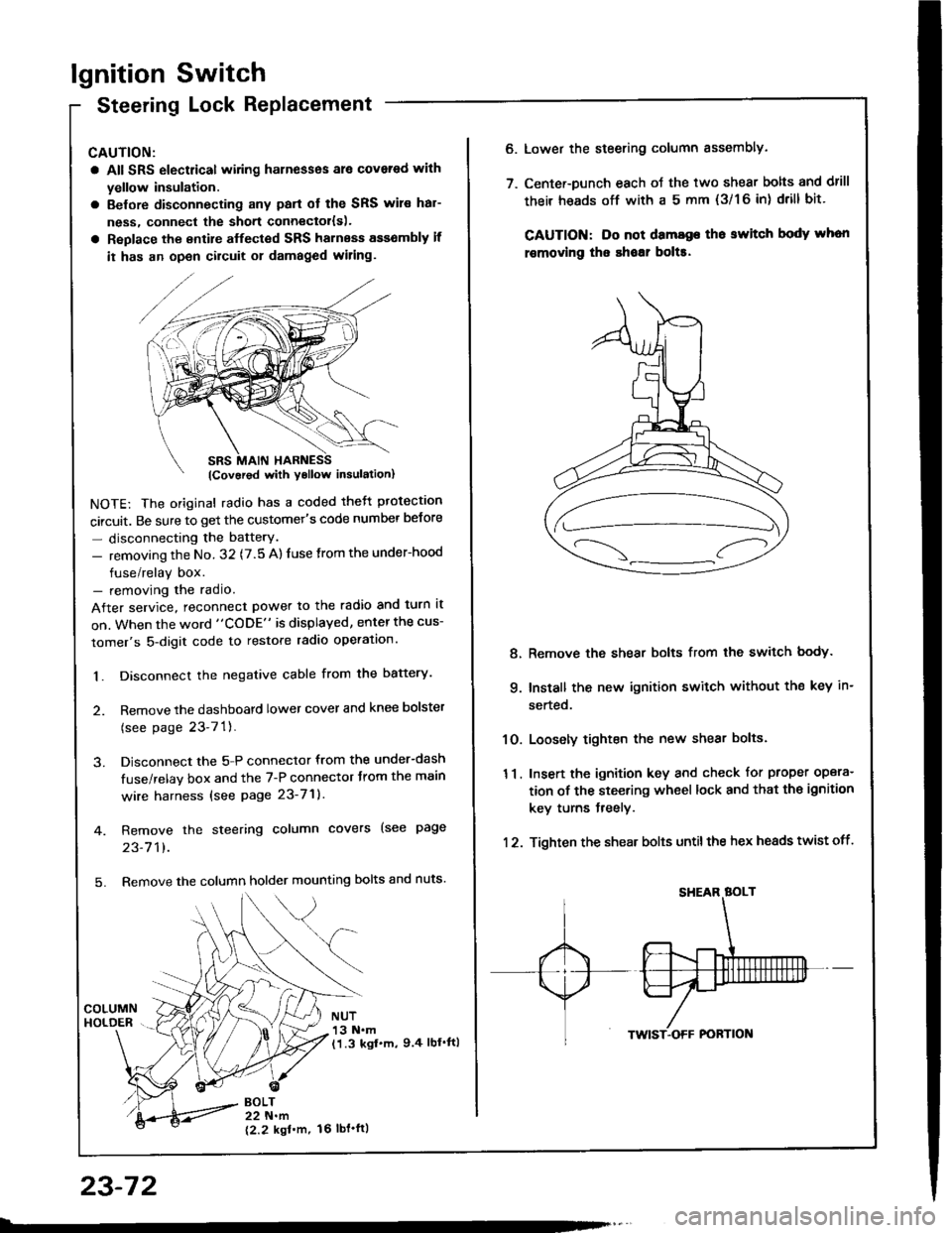
5. Remove the column holder mounting bolts and nuts'
BOLT22 N.m
12.2 kgl'm.
NUT13 N.m(1.3 kgf.m, 9.4 lbl'ftl
23-72
16 tbt.ftl
6. Lower the steering column sssembly.
7. Center-Dunch each oJ the two shear bolts and drill
their heads off with a 5 mm {3/1 6 in) drill bit'
CAUTION: Do not dama96 tho switch body whon
r€movlng the shoar bol$.
Remove the shear bolts from the switch body.
Install the new ignition switch without the key in-
serted.
Loosely tighten the new shear bolts.
Insert the ignition key and check for proper opera-
tion of the steering wheel lock and that th€ ignition
key turns freely.
Tighten the shear bolts untilthe hex heads twist off.
8.
q
10.
11.
12.
Page 1226 of 1413
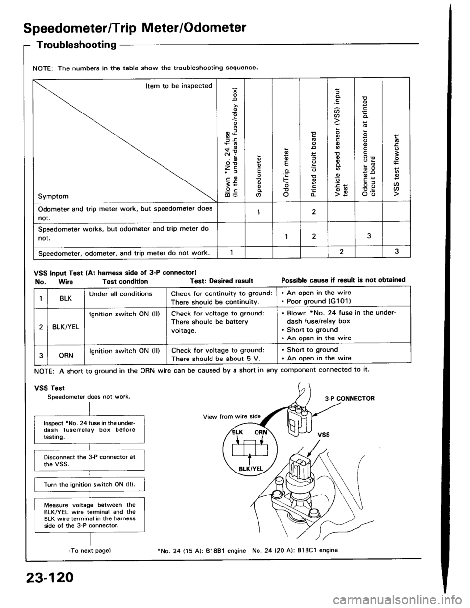
Speedometer/Trip Meter/Odometer
Troubleshooting
NOTE: The numbers in the table show the troubleshooting sequence.
Item to be inspected
Symptom
-9
;6+*c.r i.(D
zc*f
;59cd)=
E
a
6
E
'iF
o
(L
:lt)a
o
-9
>g
q)
qlv
E
'
E
oo
Odometer and trip meter wotk, but speedometer does
not.12
SDeedometer works, but odometer and trip meter do
nor,1
Speedometer. odometer, and trip meter do not work.
VSS Input Test (At ham€ss side of 3-P connector)
No. Wir6Tost conditionT€st: Desirsd resultPossible cause it result is not obtained
1BLKUnder all conditionsCheck for continuity to ground:
There should be continuity.
. An open in the wire. Poor ground (G1O1)
BLK/YEL
lgnition switch ON (ll)Check tor voltage to ground:
There should be battery
voltage.
Blown *No. 24 fuse in the unde.-
dash tus€/relay box
Short to ground
An open in the wire
ORNlgnition switch ON (ll)Check for voltage to ground:
There should be about 5 V.
. Shon to ground
. An open in the wire
NOTE: A short to ground in the
vSS Tost
Speedometer does not work.
ORN wire can be caused by a short in any component connected to lt.
3-P CONNECTOR
Inspect 'No. 24luse in the under-dash tuse/relay box beloretesting.
Turn the ignition switch ON lll).
Measure voltage between theBLK/YEL wire terminal and the8LK wire terminal in the harnessside of the 3-P connector.
{To next page)
23-120
24 (15 A): 81881 engine No. 24 {20 A): 818C1 engine
Page 1290 of 1413
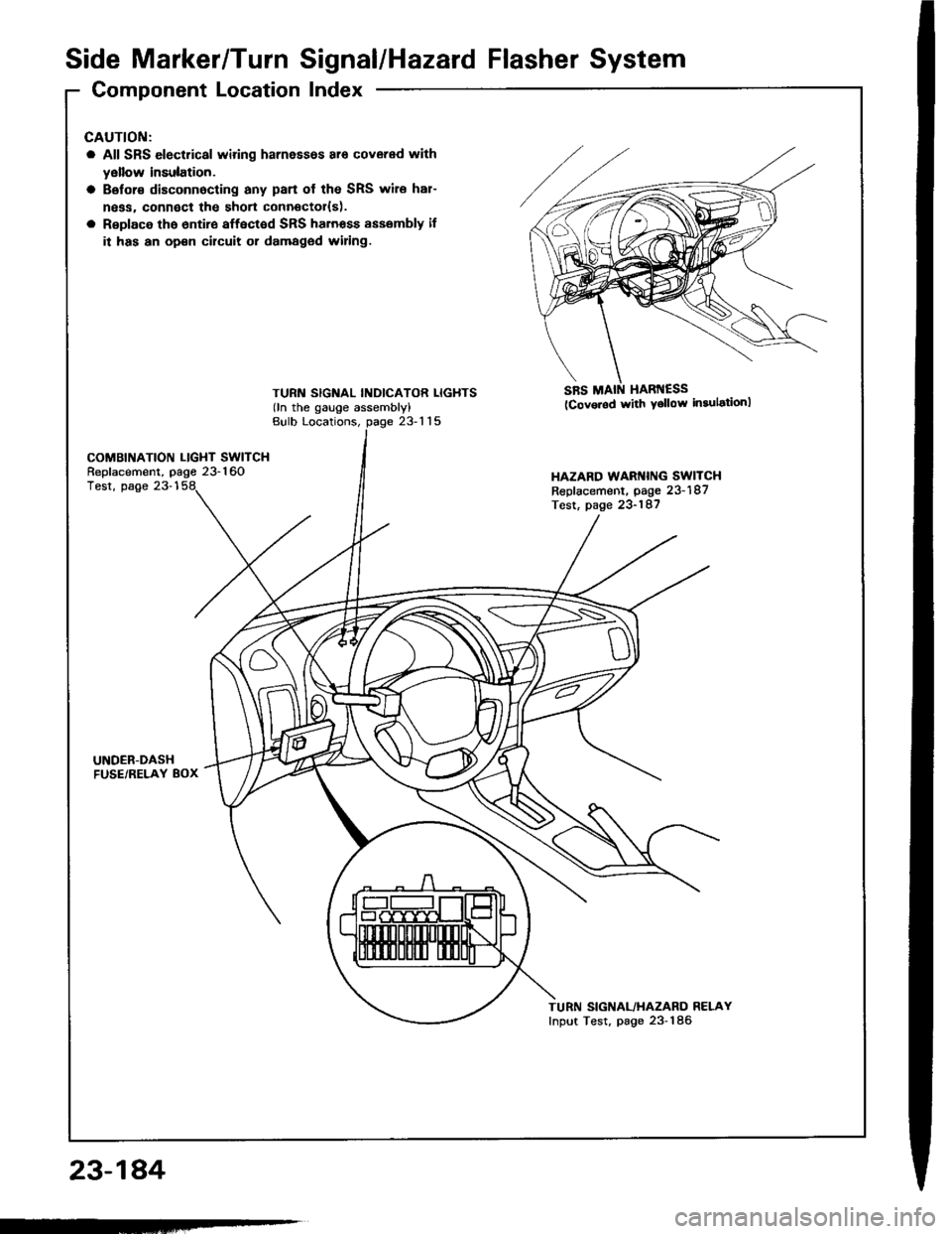
Side Marker/TurnSignal/Hazard Flasher System
Component LocationIndex
23-184
GAUTION:
a All SRS electrical wiring harnessos ar6 covered with
yellow insulation.
a Belor€ disconnocting any pan of the SRS wire har-
ngss, connoct the short connector{s).
a Rsplace tho 6ntir€ affect€d SRS harnoss sssembly il
it has an op€n cilcuit or damaged widng.
TURN SIGNAL INDICATOR LIGHTS(ln the gauge assembly)
SRS MAIN HARI{ESS(Cov.rod with Ysllow in3ulationl
Bulb Locations,23-115
COMBINATION LIGHT SWITCHReplacement, page 23-160HAZARD WARI{ING SWITCHReplacement, page 23-187Test, page 23-187
Test, page 23-1
UNDER-DASHFUSE/RELAY 8OX
TURN SIGNAL/HAZARO RELAYInput Test, page 23-186
-
Page 1292 of 1413
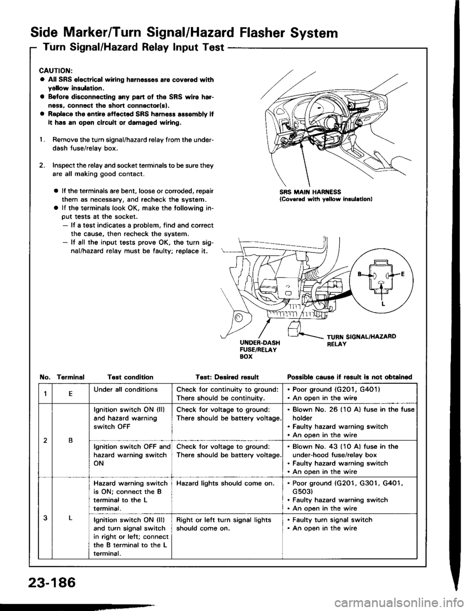
Side Marker/Turn Signal/Hazard Flasher System
Turn Signal/Hazard Relay Input Test
CAUTION:
a All SRS electrical wiring harn6ss6s ar€ covered with
yellow insulation.
a B€foro disconn6cting any part of th€ SRS wire har-
noss, connoct tho short connector(s).
a Replaco tho ontiro sftoctod SRS harness ass€mbly it
it has an open circuit or damagod wiring,
I . Remove the turn signal/hazard relay from ths under-
dash Juse/relay box.
2. Inspect the relay and socket terminals to be sure they
are all making good contact.
a It the terminals are bent, loose or coroded, repair
them as necessary, and recheck the system.
a lf the terminals look OK, make the tollowing in-
put tests at the socket.- lf a test indicates a problem, find and correct
the cause, then recheck the system.- lf all the input tests prove OK, the turn sig-
nal/hazard relay must be taulty; replace it.
UI{DEB-DASHFUSE/RELAYBOX
Test: D€sired rosult
SBS MAIN HAR ESS{Covg.ed with yollow inrulltion)
TelminalTeEt conditionPo$iblo causo it fosult is not obtainod
,lEUnder all conditionsCheck for continuity to ground:
There should be continuitv.
. Poor ground (G201 , G4O1). An oDen in the wire
2B
lgnition switch ON (ll)
and hazard warning
switch OFF
Check for voltage to ground:
There should be battery voltage.
Blown No. 26 (10 A) fuse in ths fuse
holder
Faulty hazard warning switch
An open in the wire
lgnition switch OFF and
hazard warning switch
ON
Check for voltage to ground:
There should be battery voltage.
Blown No. 43 (10 Al fuse in the
under-hood fuse/relay box
Faulty hazard warning switch
An ooen in the wire
3
Hazard wa.ning switch
is ON; connect the B
terminal to the L
termrnat.
Hazard lights should come on.Poor ground (G2O1, G3O1, G4O1
G503)
Faulty hazard warning switch
An open in the wire
lgnition switch ON (lll
and turn signal switch
in right or left; connect
the B terminal to the L
terminal.
Right or left turn signal lights
should come on.
. Faulty turn signal switch. An open in the wire
23-186
-
Page 1305 of 1413
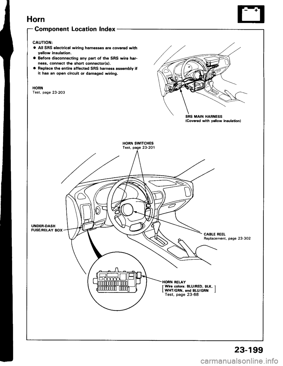
Horn
Component Location Index
CAUTION:
a All SRS €lectricsl wiring harnesses al€ covered with
yellow insulation.
a B€fore disconnecting any part of the SRS wiro har-
neaa, connect tho short connectol(sl.a Replaco the entire aftected SRS harness assembly ifit haa an open circuit ot damaged wiring.
HORNTest, page 23'2O3
HORN SWITCHESTest, pago 23-2Ol
UNDER.DASHFUSE/RELAY BOXCABLE REELRepfacement, page 23-302
HORN RELAY
I Wiro coloB: BLU/RED, BLK, IIWHT/GRN, and BLU/GR lTest, page 23-68
{Covo.ed wiih yollow insulationl
<------\-\----.....=
23-199
Page 1307 of 1413
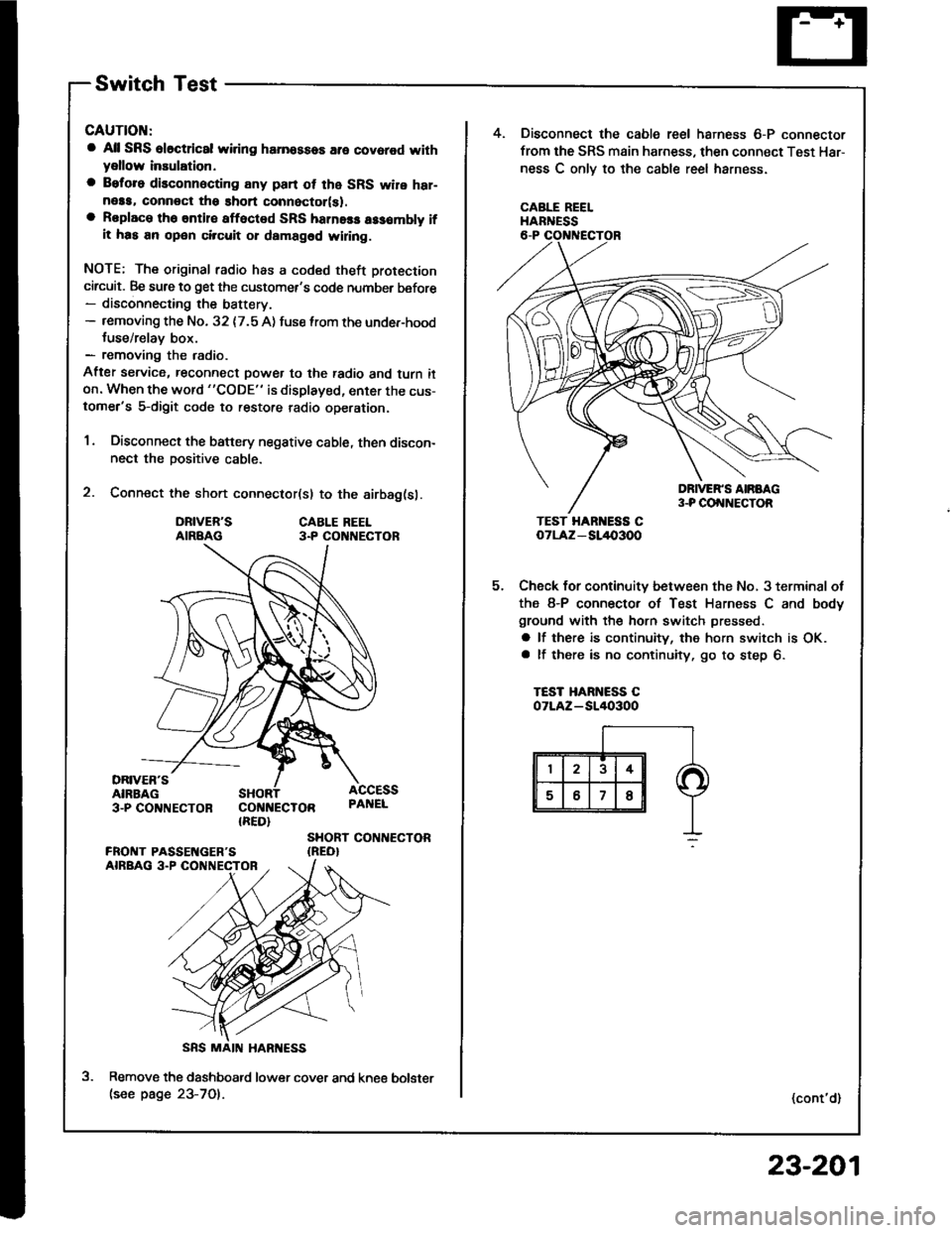
Switch Test
CAUTION:
a All SRS el6ctrical wiring harnossos are covarod withyellow inaulation.
a Beforo disconnecting any pan ot the SRS wire har-neaa, connoct ths short connector(s).a Roplace the entil€ afloctod SRS harne$ a$6mbly ifit has an open circuit or dsmagad wlring.
NOTE; The original radio has a coded theft protection
circuit. Be sure to get the customer's code number before- disconnecting the battery.- removing the No. 32 {7.5 A) fuse lrom the under-hoodtuse/relav box.- removing the radio.
After service, reconnect power to the radio and turn iton. When the word "CODE" is displayed, enter the cus-tomer's 5-digit code to restore radio operation.
1. Disconnect the battery negative cable, then discon-nect the positive cable.
2. Connect the short connector(sl to the airbag(sl.
DRIVER'SAIRBAGCABLE REEL3.P CO NECTOR
DRIVER'SAIRBAG3-PCO'TNECTOR COI{NECTOR{RED}
ACCESSPAI{EL
SHORT CONTIECTOR{REO}
Remove the dashboatd lower cover and kne€(see page 23-701.
5.
4. Disconnect the cable reel harness 6-P connector
from the SRS main harness, then connect Test Har-
ness C onlv to the cable reel harness.
CABLE REELHARNESS
TEST HAR ESS CoTLAz - SL/l{,3OO
Check for continuity between the No, 3 terminal ot
the 8-P connector of Test Harness C and body
ground with the horn switch pressed.
a lf there is continuity, the horn switch is OK.a lf there is no continuity, go to step 6.
TEST HARNESS COTLAZ-SI/I()3OO
(cont'd)
bolster
23-201
Page 1354 of 1413
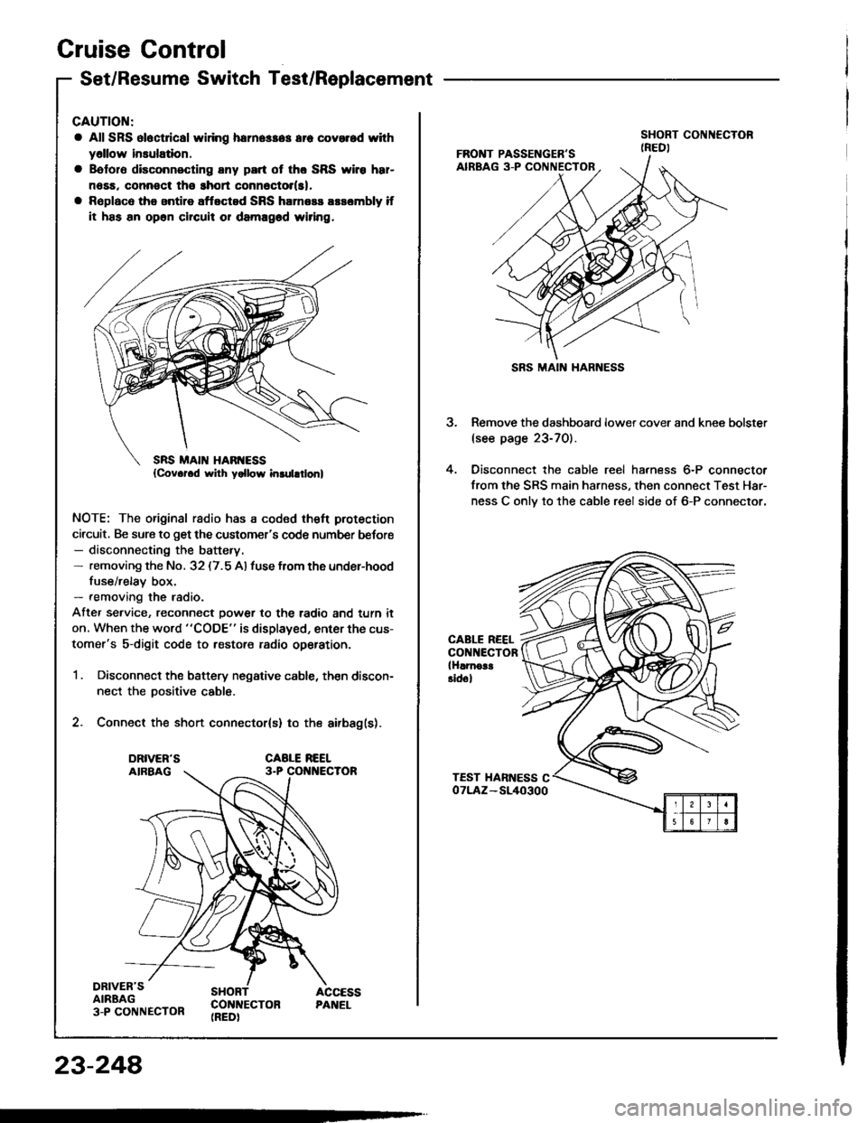
Cruise Gontrol
Set/Resume Switch Test/Replacement
CAUTION:
a All SRS ol6ct cal widng herne$a3 err covorod with
y6llow insulation.
a Bototo disconnecting any part ot tho SRS wiro h8r-
n6sa, connoct tho ghort connector(sl,
a Rsplaco the antire aftected SRS harness arsombly if
it has an op6n chcuit or damagod wiring.
NOTE: The original radio has a coded theft protection
circuit, Be sure to get the customer's code number befor€- disconnecting the battery.- removing the No. 32 (7.5 A) fuse from the under-hood
fuse/relay box.- removing the radio.
Afte, service, reconnect power to the radio and turn it
on. When the word "CODE" is displayed, enter the cus-
tomer's s-digit code to restore radio op€ration.
1 . Disconnect the battery negative cable, then discon-
nect the Dositive cable.
2. Connect the short connector(s) to the airbag(s).
DRIVER'SAIRBAG3-P CONNECTOR
SHORT ACCESSCON]TECTON PANEL(REDI
23-248
SRS MAIN HARNESS
3. Remove the dashboard lower cover and knee bolster(see page 23-70).
4. Oisconnect the cable reel harness 6-P connector
from the SRS main harness, then connect Test Har-
ness C onlv to the cable reel side of 6-P connector.
CABLE REELCONNECTORlHlrnoa!Eidol
Page 1372 of 1413
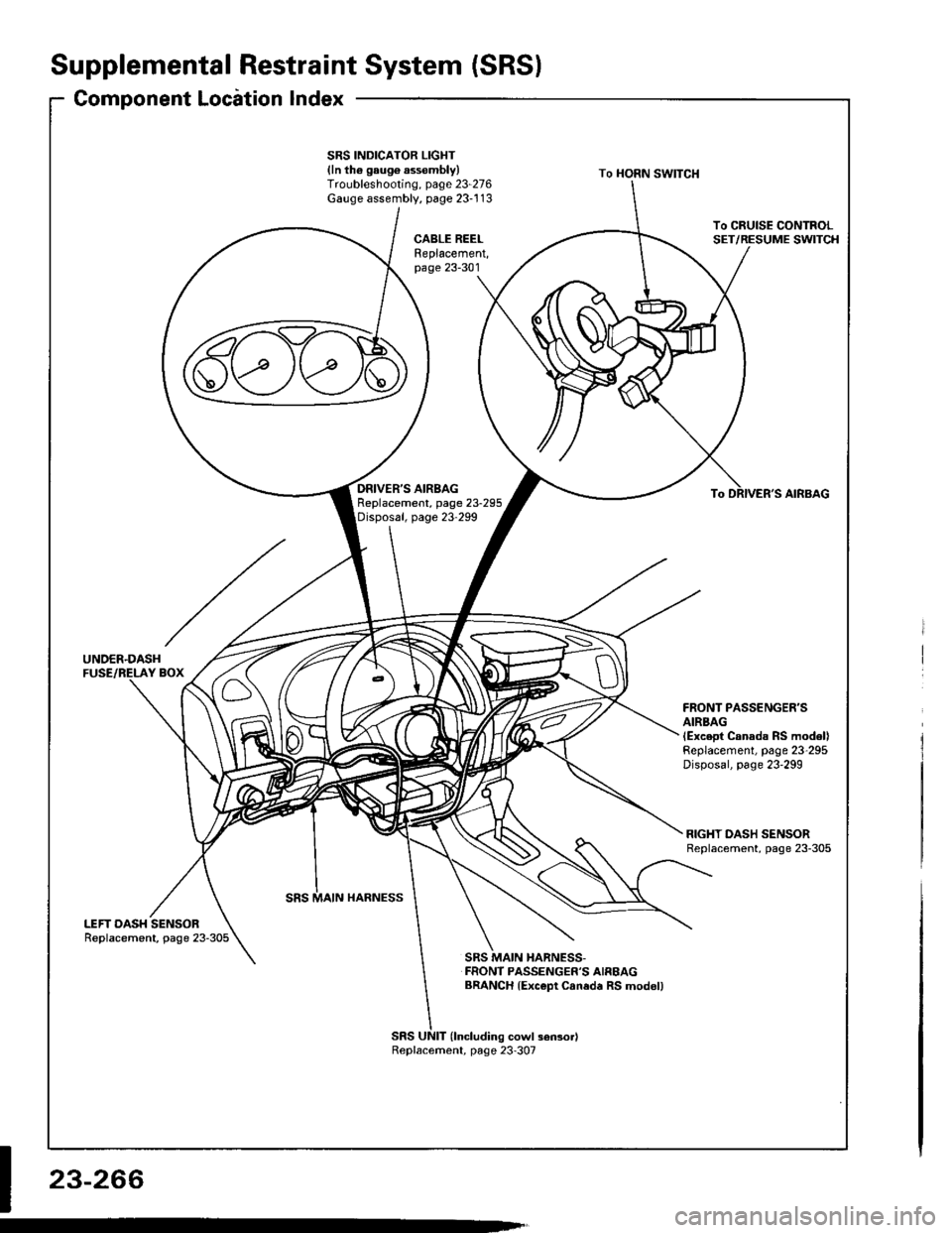
Supplemental Restraint System (SRS)
Component Locirtion Index
UNDER.DASHFUSE/RELAY BOX
SRS INDICATOR LIGHT(ln th6 gaug6 assembly)Troubleshooting, page 23-276Gauge assembly, page 23-113
CABLE REELReplacement,page 23-301
AIRBAGBeplacement, page 23.295
SRS UNIT (lncluding cowl sensorl
SRS MAIN HARNESS-FRONT PASSENGER'S AIREAGBRANCH lExc€pt Caned. RS modol)
To CRUISE CONTROLSET/RESUME SWITCH
RIGHT DASH SENSORReplacement, page 23-305
FRONT PASSENGER'SAIRBAGlExcept Canads RS model)Replacement, page 23-295Disposal, page 23'299
LEFT DASH SENSORReplacement, page 23-305
23-266
Replacement, page 23-307