heater HONDA INTEGRA 1994 4.G Service Manual
[x] Cancel search | Manufacturer: HONDA, Model Year: 1994, Model line: INTEGRA, Model: HONDA INTEGRA 1994 4.GPages: 1413, PDF Size: 37.94 MB
Page 1067 of 1413
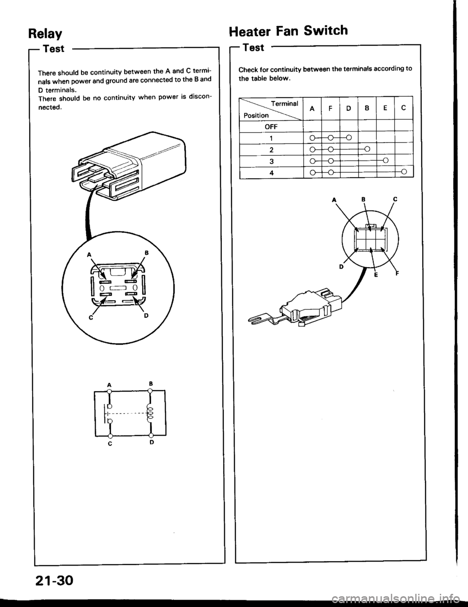
Relay
There should be continuity b€tween the A and C termi-
nals when Dower and ground are connected to the B and
D terminals.
There should be no continuity when power is discon-
nected.
Heater Fan Switch
Check for continuitv bstween the terminals according to
the table below.
Terminal
PositionADBE
OFF
,lo--o
o--o
3o--o
4-o
rl
I
I
r?
21-30
Page 1086 of 1413
Troubleshooting
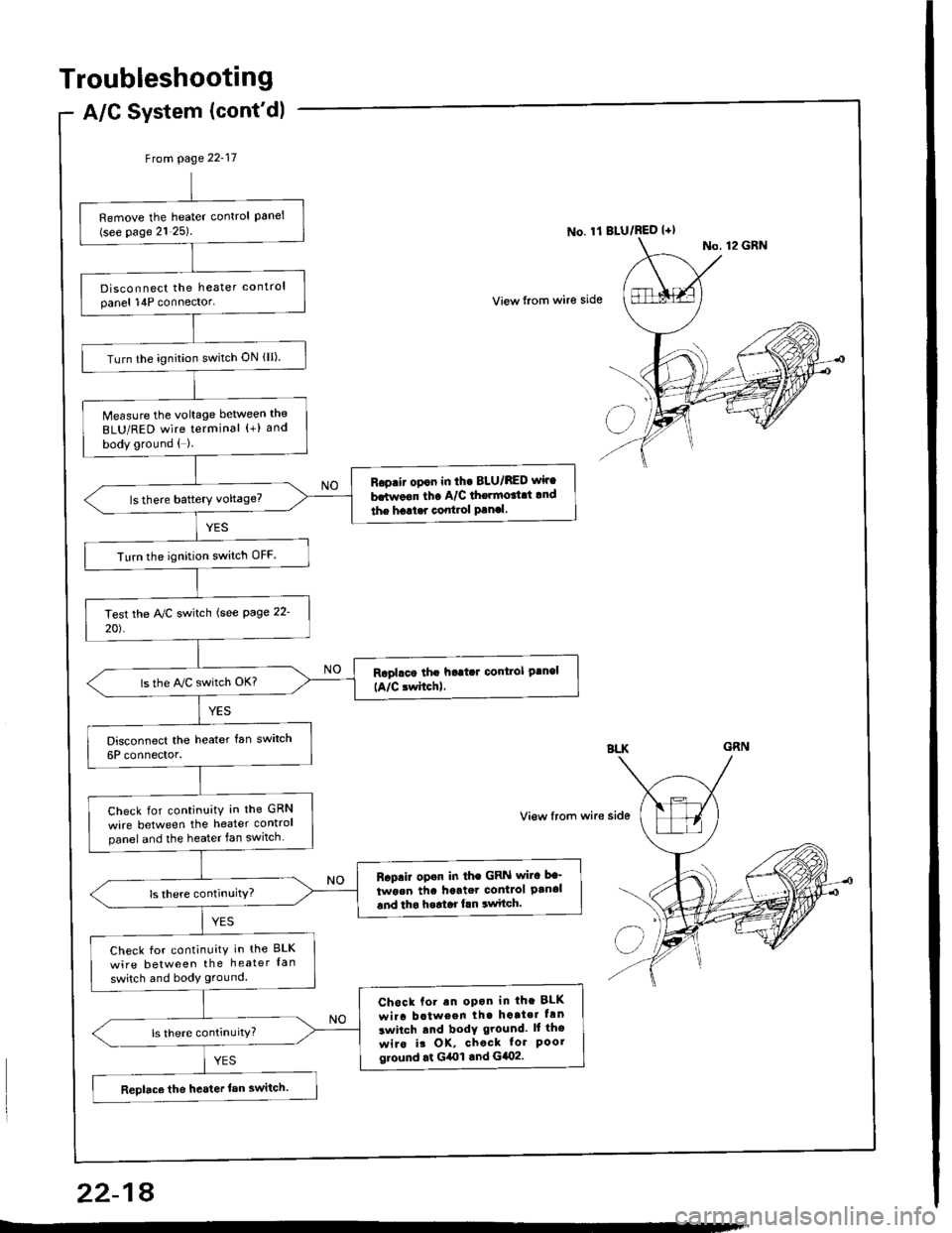
Remove the heater control Panel(see page 21 25)
Disconnect the heater controlpanel 14P connector'
Turn the ignition switch ON (lI).
Measure the voltage between the
BLU/RED wire terminal (+) and
body ground { }
Rop.i. opon in tho BLU/BED wir.
b.twoon tha A/C thermort.t lnd
the haat.r control Panal
Turn the ignition switch OFF.
ls the A/C switch OK?
Check for continuitY in the GRN
wire between the heater controlpanel and the heater fan switch
R.prir op.n in the GRN wiro be'
twoen thc hartet contlol Panaland tho h.rtor fln switch.
Check for continuity in the BLK
wire between the heater {an
switch and body ground.
Chock fol an opon in the BLK
wi.a b.tween th. hotte. hn
lwitch tnd bodY ground. ll tho
wiro it OK, chock for Poorg.ound .t G4ol .nd G402.
Replace the heater lan switch.
Frcm page 22'17
View lrom wire side
A/C System (cont'dl
No. 11 BLU/RED l+l
22-18
Page 1092 of 1413
A/G System Service
Performance Test
The performance test will help determine if the air con-
ditioner system is operating within specitications.
Only use service equipment that is U.L.-listed and is cer-
tified to meet the requirements of SAE J2210 to remove
HFC-134a {R-134a) from the air conditioner system.
CAUTION: Exposure to air conditioner relrig€rant and
lubricant vapor ot mist can irritate eyes, nose and
throat. Avoid breathing the air conditioner rstrigerant
and lubricant vapor or mi3t.
It accidental system discharge occurs, ventilate work
area before resuming service.
R-134a service equipment or vehicle air conditioner sys-
tems should not be pressure tested or leak tested with
comPressed atr.
!@ some mixtures ot air and R'1344 hrv6
been shown to be combustibls at elovatod prsssurel
and can result in firg or explosion causing iniury 01
property damage. Ngvor usg compregsed ail to prossuro
t€st R-134a ssrvice equipment or vohicl€ air conditioner
syst€ms.
Additional health and safety information may be
obtained from the refrigerant and lubricant manufactur-
ers.
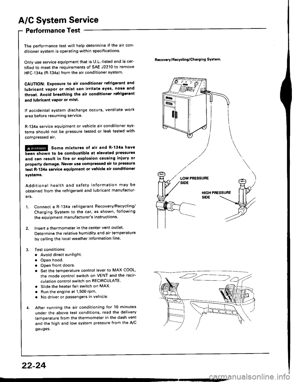
1. Connect a R-134a refrigerant Recovery/Recycling/
Charging System to the car, as shown, iollowing
the equipment manufacturer's instructions.
2. Insert a thermometer in the center vent outlet.
Determine the relative humidity and air temperature
by calling the local weather information line,
3. Test conditions:
. Avoid direct sunlight.
. Open hood.
. Open front doors
. Set the temperature control lever to MAX COOL,
the mode control switch on VENT and the recir-
culation control switch on RECIRCULATE.
. Slide the heater fan switch on MAX
. Run the engine at 1,500 rPm
. No driver or passengers in vehicle.
4. After running the air conditioning for 10 minutes
under the above test conditions. read the delivery
temperature from the thermometer in the dash vent
and the high and low system pressure from the A,/C
gauges.
Rocov.rylB.cycling/Ch!lging SFtrm.
PRESSURELOW
22-24
Page 1107 of 1413

Electrical
Special Tools
Troubleshooting
Tips and Precautions ................................ 23-3Five-stop Tloubleshooting ..............,...-..-... Z3-sSchematic Symbols ................................_. 23-6wire Color Cod€s ..................................... 23-6Relay and Control Unit Locations
Engine Compartment .........,............ ... --. 23-7Dsshboard and Door ..,,......................... 23-gDashboard and Floor ............................. 23-t OOuaner Panel .....-.....23-12Connector ldentification and WireHarness Routing ........ 23-i 3
Index to Circuits and Systems
Airbag ............... ...-..-... 2g-26sAir Conditioning ....,.. Section 2lAltelnator ......_.............. 23-99Anti-lock Brake Systsm (ABS) Section 19Automatic Transmission Section 14Battery .............. .......... 23-66Chafging System ........... 23-98rCigalstte Lighter .....................-...-......-..-.. Z3-2O4Cfock ................. ..........23-197rcruise Controf .......--..-... 23-242Distributor .................... 23-87Fan Controls ................. 23-1ogFuel and Emissions ... Section 1i*Fuses
Under-dash Fuse/Relay Box ................... 23-48Undor-hood ABS Fuse/Retay Box ............ 23-51Under-hood Fuse/Relay Box,.................. 23-52rGauges
Engine Coolant Temperature {ECT)Gauge ................ ..23-126Fuef cauge ............... 2g-123'Gauge Assembly ....--.23-113Speedometer .....-...,,. 23-114Tachometer .....,.....-.. 23-114Ground Distribution ........ 23-60Heater ,,,........,.... ..... Section 2lrHorn ................. ........... 23-199*fgnition Switch ............. 23-70fgnition Syst6m .......-..-.. 23-A7lgnition Timing .............. 23-89Indicator Lights"A/T Gear Position .............. ................... 23-1 32B1ak6 System ...,..,..-.23-127Engine Oil Pressura .............................. _ 23-1 51Low Fuel ............ ......23-125Malfunction Indicator Lamp {MlL} ...,,. Section I l
tfnteglated Control Unit ...29-144*lnterlock System ...................................... 23-1 3gLights, Exteriol
Back-up Lights ........... 23-179Brake Lights .............. 23-t8ltDaytime Running Lights {Csnada} ........... 23-156Front Palking Lights ............................. 23-1 65Flont Side Marker Lights ....................... 23-165Front Turn Signal Lights ........................ 23-1 65*Hazard Warning Lights .........................- 2g-1A4Headlights ................. 23-t6tLicense Plate Lights .............................. 23-1 69Taillights(Harchback) .......... 23-166
{Sedan) .............. .. 23-167Lights. Inteliol
Cargo Area Light {Hatchback) ...... -.. -.. -... 23-177Ceifing Light ........-..-.23-175
Dash Lights Blightness Controt .............. 23-t70Glove Box Lighr ................................... 23-1 69Spotfighr ............ ....-.23-174Trunk Light (Sedanl ............... .............. - 23.-177*Lighting Sysrem .......-.-... 23-152:Moonroof ,,.,.......,..,,,,,.-.23-211PGM-FI Systom ........ S€crion 11Power Distribution .,.-..--..23-54Power Door Locks .............,,..................... 23-233Power Mirors ..,..,....-...- 23-216Power Relays ...........,..... 23-68Power Windows ............ 29-222*Rear Window Defogger ........,... ..........,..... - 23-20,6Reminder Systems
Key-in Remindel System ....,.............,.... 23-1 50Lights-on Reminder System ................... 23-l 5f*Maintenance Reminder system ..,,.... -.. - -. 23-.1 2gSeat Belt Reminder System ..................- 23-125*Side Markel/Turn Signal/Hazard
Ffasher System .,..,..-.23.-1A4Spark Pfugs .........-...-..... 23-97Starting System ....,,.....-. 23-73*Stereo Sound System ...,.......................,,.. 23-l gg
Supplemental Restraint System {SRS} ......... 23-265Vehicfe Speed Sensor {VSS) .............--..-.... 23-122*Wiper/Washer Systom ...............--.........-..- Zg-254
rRead SRS pi€cautions on Page 23-271 betore workingin these areas.
-+
Page 1112 of 1413
Troubleshooting
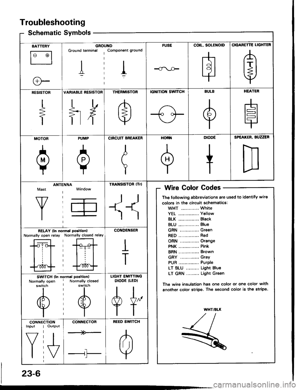
Schematic Symbolsym
BATTERY
le @l
ll
e-
GROIGround terminal
I
,ltDComponont ground
I
FUSECOIL, SOLENOID
H
CIGANETTE LIGHTER
A
t+j
RESISTOR
+
VARIABLE RESISTOR
ilH
THERMISTOR
e
tcNtTtol{ swTcH
-1o oF
BULB
e
HEATER
H
MOTOR
a
PUMP
0
CIRCUIT BREA(ER
I
T
HORI'
+
DIODE
+
SPEATER, BUZZER
D
Mast
Y
ANTIINNATRA SISTOR lTrl
II
Wire Golor Codes
The tollowing abbreviations are used to identity wire
colors in th€ circuit schematics:
wHT ............ White
YEL .............. Y6llow
BLK .............. Black
BLU .............. Blue
GRN ............. Green
RED.............. Red
ORN ............. Orange
PNK .............. Pink
BRN .............. Brown
GRY ............. Gray
PUR .............. Purple
LT BLU ......... Light Blue
LT GRN ......... Light Gr€en
The wi.e insulation has one color or one color with
another color stripe. The s€cond color is the stripe.
WHT/ALK
,/t,/l./l--
R
RELAY {ln noNormally open relayrmal poritionl
Normally closed relay
*Gt-i- |
lll
l'*^f
CO'IDENSER
I
T
SWITCH (ln ngrmal position)
Normally open ' Normally closodswitch I switch
til
@@
lil
LIGHT EMITTINGDIODE (LEDI
A[,
TT
CONNEInpur
f7
I
CTIONOutput
I\/
CONNECTON
--+>-
tl'l
BEED SWITCH
A
lril
Y
23-6
Page 1119 of 1413
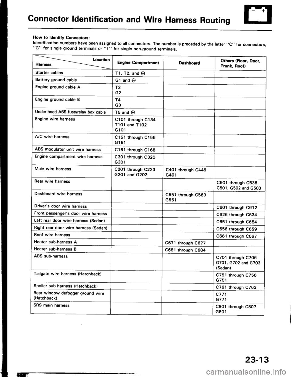
Connector ldentification and Wire Harness Routing
How to ldentity ConnoctolS:
ldentification numbers have been assigned to all connectors. The number is preceded by the letter ,,C,, for connecrors,"G" for single ground terminals ot "f" hr single non-ground terminals.
Location
HamessEngino CompartmontDarhboardOthors (Floor, Door,
Trunk, Rootl
Starter cablesT1, T2, and (E
Battery ground cableG1 and O
Engine ground cable AT3
Engine ground cable BT4
G3
Under-hood ABS fuse/relav box cableT5 and (D
Engine wire harnessC101 through C134
Tl Ol and T102
G 101
A/C wire harnessCl 5'l through C156
G151
ABS modulator unit wir€ harnessC161 through C168
Engine companment wire ha.nessC3O'l through C32O
G301
Main wire hatnessC2O1 through C223
G2Ol and G2O2
C4O1 through C449
G401
Rear wire harnessC501 through C536
G501, G502 and G5O3
DashboSrd wire harnessC551 through C569
G551
Driver's door wire harnessC601 through C612
Front passenger's door wire harnessC626 through C634
Left rear door wire harness (Sedan)C651 through C654
Right rear door wire harness (Sedan)C656 through C659
Roof wire harnessC661 through C667
Heater sub-harness AC671 through C677
Heater sub-hatness BC681 through C684
ABS sub-harnessC7O1 through C7O6
G7O1, G702 and G703(Sedan)
Tailgate wire harness (Hatchback)C751 through C756
Spoiler sub-ha.ness (Hatchback)C761 through C763
Rear window defogger ground wire(Hatchback)c77'l
G771
SRS main harnessC8O1 through C8O7
G801
23-13
Page 1130 of 1413
Connector ldentification and Wire Harness Routing
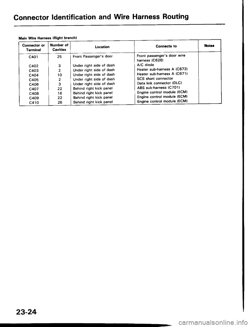
Main Wire Ha.ness {Right branch}
Connactor or
Terminal
Numbsr of
Caviti€sLocationConnscts tottlotor
c401
c402
c403
c404
c405
c406
c407
c408
c409
c410
,E
10
2
22
lo
22
26
Front Passenger's door
Under right side of dash
Under right side ot dash
Under right side of dash
Under right side of dash
Under right side ot dash
Behind right kick panel
Behind right kick panel
Behind right kick panel
Behind right kick panel
Front passenger's door wire
harness (C626)
A/C diode
Heater sub-harness A (C672)
Heater sub-harness A {C671}
SCS short connectol
Data link connector (DLC)
ABS sub-harness (C7011
Engine control module (ECM)
Engine control module (ECM)
Engine control module (ECMI
23-24
Page 1152 of 1413
Connector ldentification and Wire Harness Routing
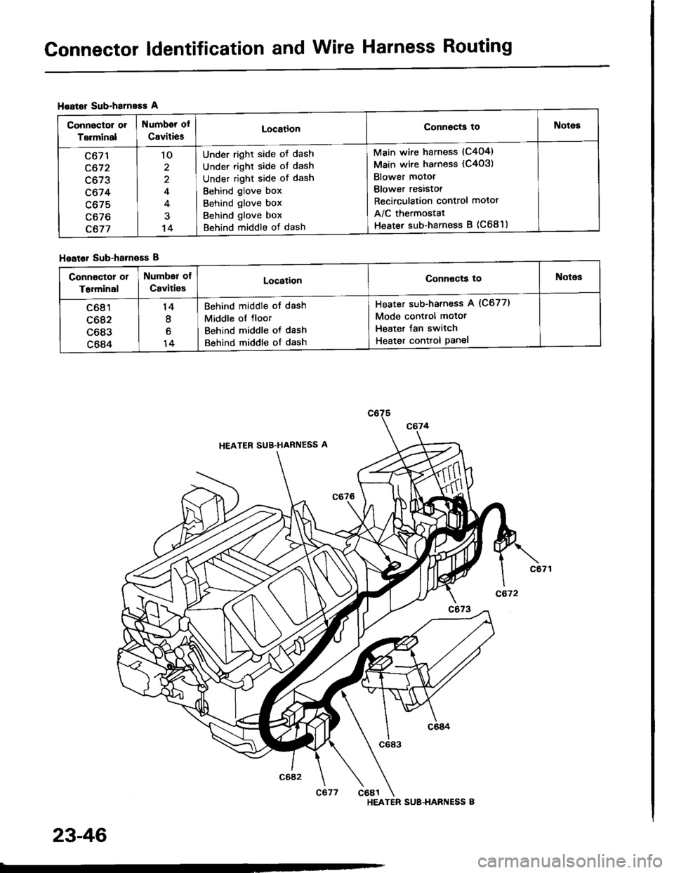
Hoator Sub-harneEs A
Hoator Sub-hameEs B
Connoctor or
Terminal
Numb€r of
CavitiesLocationConn6cts toNotog
c671
c672
c673
c674
c675
c676
c677
'lo
2
4
4
14
Under right side ot dash
Under right side of dash
Under right side of dash
Behind glove box
Behind glove box
Behind glove box
Behind middle of dash
Main wire harness (C404)
Main wire harness (C4o3)
Blower motor
Blower resistor
Recirculation control motot
A/C thermostat
Heater sub-harness B (C681)
connoctor 01
T6rminal
Number of
CavitioELocationConnocts toNotos
c681
c682
c683
c684
14
I
6
14
Behind middle of dash
Middle ol floor
Behind middle of dash
Behind middle of dash
Heater sub-harness A (C677)
Mode control motor
Heater Jan switch
Heater conttol Panel
HEATER SUB-HARI{ESS B
23-46
Page 1276 of 1413
UNDER. HOOD FUSE/REIAY 8OX
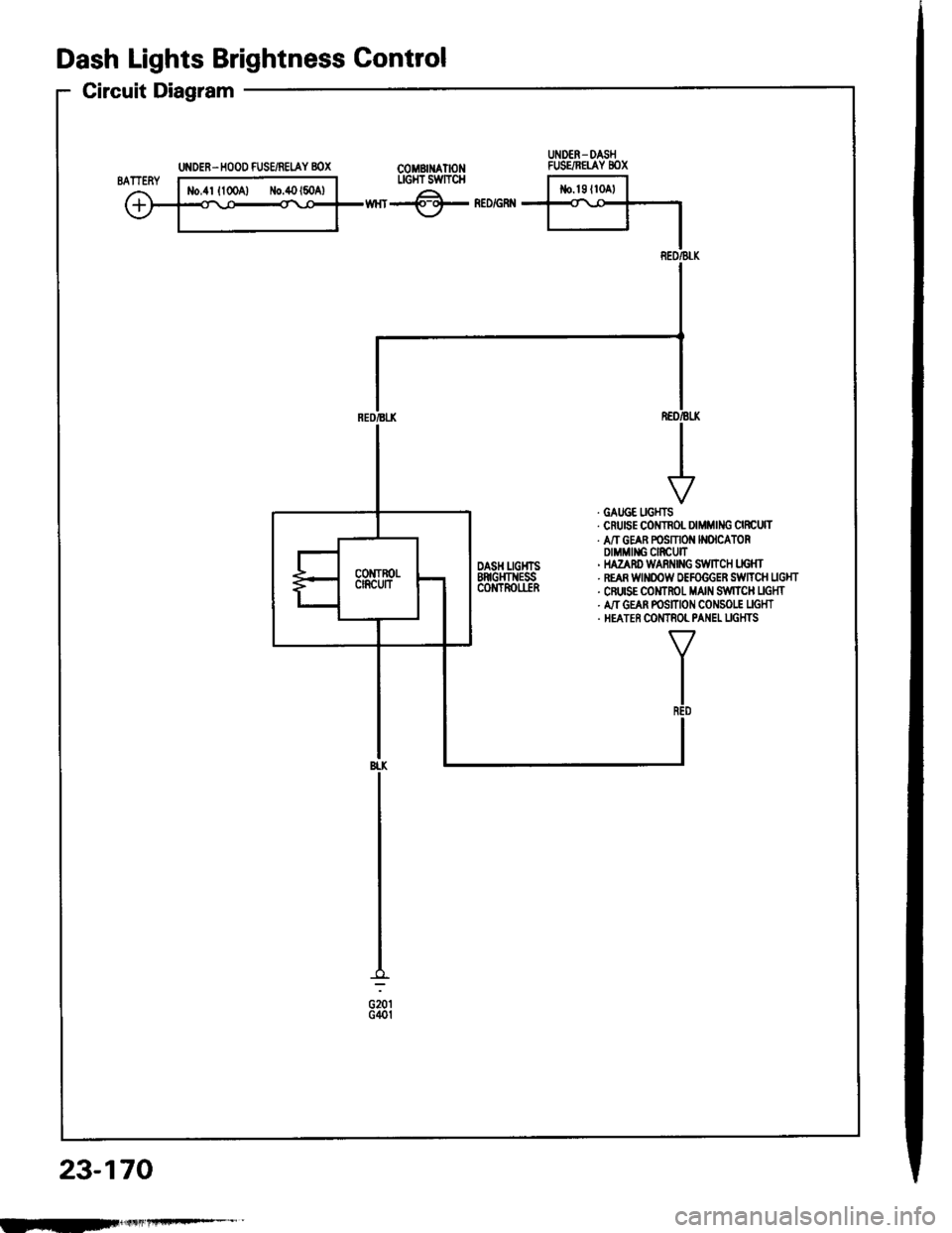
Dash Lights Brightness Gontrol
Circuit Diagram
COMBII{ATIONLIGI{T SWTTCH
wnr-@- neorenn
REO/BLK
. GATJGE UGHTS. CruEE COITNOL DIMMING CIRCUTT. A/T GEAR POSMON N(ICATORDIMMII{G CIRCUIT' HAZAnD WARi{|NG S:WltCH LIG}fr. REAR WINOOW OEFOGGER SiWTTCH UGHT. CFUISE COMTROT MAIN S,IVITCH UGHT. A,IT GEAN POSITION CONSO|.! UGHT. HEATER COMTNOL PANEL UGHTS
TR€D
BI.K
G201G40t
23-170
UNDER- DASHFUSE/NETAY 8OX
IEF
Page 1315 of 1413
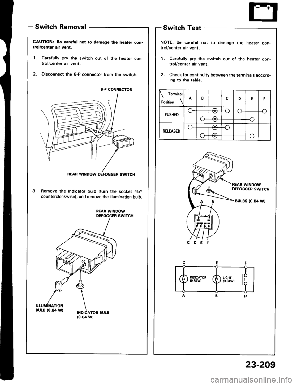
Switch Removal
CAUTION: Be caroful not to damags the hoator con-tlol/centel ail vent.
1, Carefully pry the switch out of the heater con-tfol/center air vent.
2. Disconnect the 6-P connecto, from the switch.
Remove the indicator bulb (turn the socket 45o
counterclockwise), and remove the illumination bulb.
REAR WINDOWDEFOGGER SWITCH
Switch Test
NOTE: Be caretul not to damage the heate. con-trol/center air vent.
1. Carefully pry the switch out of the heater con-
trol/center air vent.
2. Check tor continuity between the terminals acco.d-
ing to the table.
Torminal
P*il*__\IDF
PUSHEDo--oo-_o
o-
\../
-\-o
RETEASEDo-/\
o-
\:,,t
/:\\7
REAR WINDOW DEFOGGER SWITCH
[-4
I
) ll:g'", li'T
to.a4 wt
23-209