engine ground HONDA INTEGRA 1994 4.G Workshop Manual
[x] Cancel search | Manufacturer: HONDA, Model Year: 1994, Model line: INTEGRA, Model: HONDA INTEGRA 1994 4.GPages: 1413, PDF Size: 37.94 MB
Page 16 of 1413
Towing
rl
It the car needs to be towed, call a professional towingservice. Never tow the car behind another car with just
a rope or chain. lt is very dange.ous.
Emergency Towing
There are three popular methods of towing a car:
Flat-bed Equipmont-The operator loads the car on theback of a truck. This is the best way of transporting thecar.
Whsol Lift Equipment-The tow truck uses two oivot-ing arms that go under the tires (front or rear) and liftsthem otf the ground. The other two wheels remain onthe ground.
Sling-type Equipmont-The tow truck uses metal cableswith hooks on the ends. These hooks go around partsof the frame or suspension and the cables lift that endof the car off the ground. The car's suspension and bodvcan be seriously damaged if this method of towing is at-tempted.
It the car cannot be transponed by flat-bed, it should betowed with the tfont wheels oft the ground. lf due todamage. the car must be towed with the front wheelson the ground, do the tollowing:
Manual Transmission
a Release the parking brake,a Shift the transmission to Neutral.
Automatic Transmission
a Release the parking brake.a Start the engine.
a Shift to @ oosition, then to S position.
a Turn off the engine.
NOTICE: lmproper towing preparation will damage thetransmission. Follow the above procedure exactly. lf you
cannot shift the transmission or stan the engine (auto-
matic transmission), your car must be transDorted on aflat-bed.
a lt is best to tow the car no tarther than SO miles lgokm). and keep the speed below 3b mph (bE km/h).
NOTICE: Trying to litt or tow your car by the bumperswill cause serious damage. The bumpers are not designedto support the car's weight.
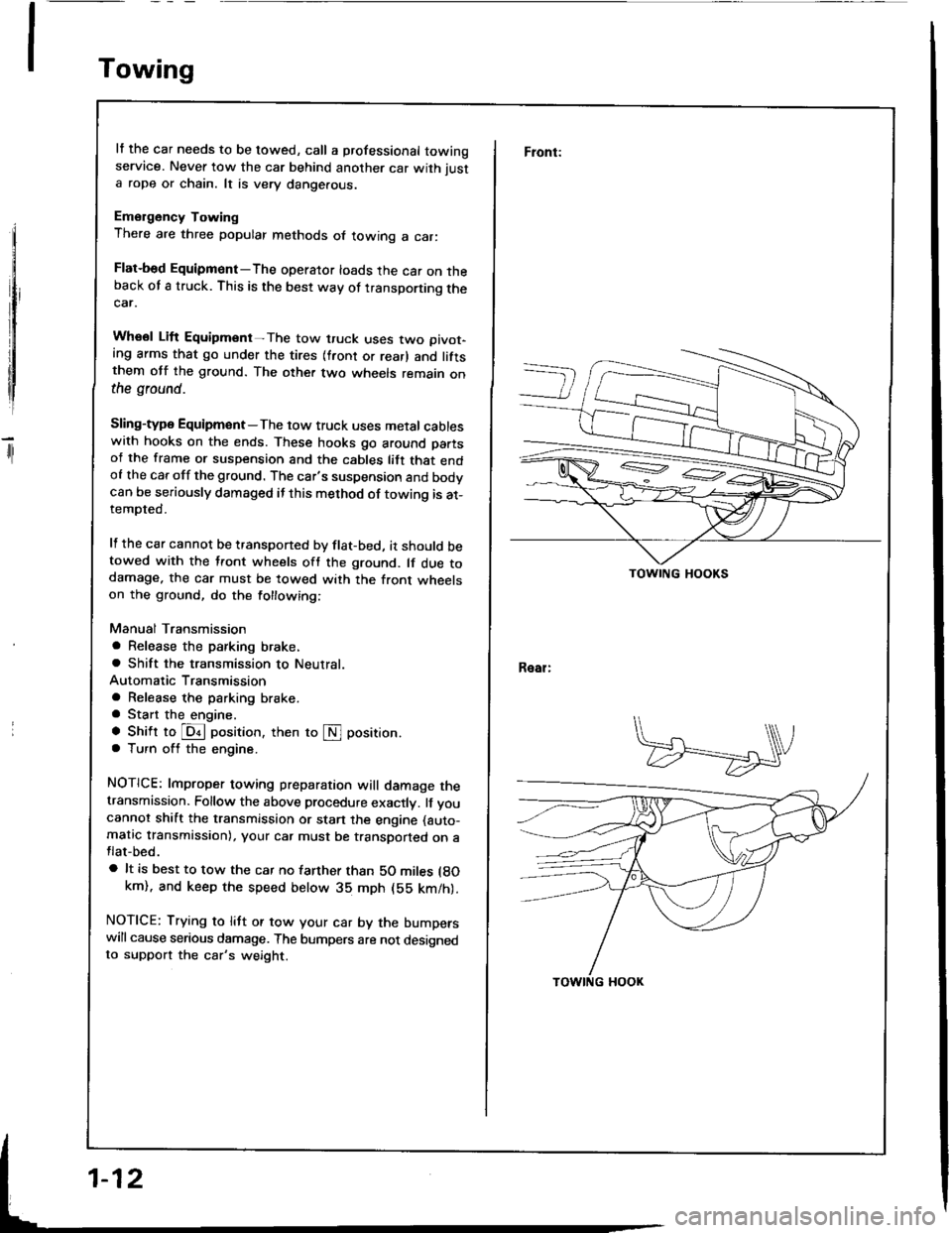
Front:
Real:
TOWING HOOKS
Page 26 of 1413
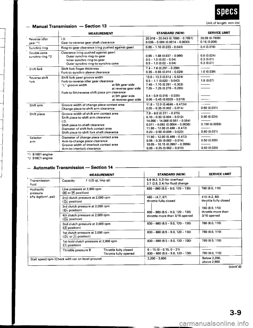
MEASUREMENISTANDARD INEW)SERVICE LIMIT
Reverse idlergear'1LD.Gear-to-reverse gear shaft clearance20.016 - 20.043 (0.7880 - 0.7891)0.036 - 0.084 (0.0014 - 0.0033)20.09 (0.7909)
0.16 (0.006)
Synchro ringRing-to-gear clearance (ring pushed against 99ar)0.85 - 1.10 (0.033 - 0.043)0.4 (0.0't6)
Oouble conesynchro ring *2Clearance {rin9 pushed against gear)
Outer synchro ring-to-gearlnner synchro ring-to-gearOuter synchro ring-to-synchro cone
0.95 r 1.68 (0.037 - 0.066)0.5 - 1.0 (0.02 - 0.04)0.5- 1.0 {0.02 -0.04)
0.6 (0.024)
0.3 (0.01)
0.3 (0.01)
Sh itt forkShift tork finger thicknessFork-to synchro sleeve clearance7.4,7.6 (0.291 - 0.299)0.35 - 0.65 (0.014 - 0.026)1.0 (0.039)
qeverse shiftShift fork pawl groove widthFork-to-reverse idler gear clearance"1" groove width at sth gear sideat reverse gear side
Fork-to-5th/reverse shift piece pin clearanceat 5th gear sideat reverse gear side
13.0 - 13.3 (0.512 - 0.524)0.5 - 1.1 10.020 - 0.043)7.40 - 7.70 (0.291 -0.303)
7.05 - 7.25 (0.278 - 0.28s)
0.4 - 0.9 {0.016 - 0.03s)0.05 - 0.45 (0.0020 - 0.018)
13907)
Shift armGroove width of change piece contact area
Change piece-to-shift arm clearance11.8 - 12.0 (0.4646- 0.4724)0.05 - 0.35 (0.002 - 0.014)0.8010.031)
Shift pieceGroove width of shift arm contact area
Shift piece'to-shift arm clearanceLD.Shift piece-to-shaft clearanceDiameter of shift Iork cont6ct areaShift piece-to-shift fork shaft clearance
7.9 - 8.0 (0.311 -0.315)
0.10 - 0.30 (0.004 - 0.012)14.000 - 14.068 {0.551 - 0.554)0.011-0.092 (0.0004 - 0.0036,1'1.90 - 12.00 (0.469 - 0.472)0.20 - 0.50 (0.008 - 0.020i
0.60 (0.024)
0.150 (0.0059)
oso to.oart
SelectorDiameter of change piece contact areaArm-to-change piece clearanceGroove widlh of interlock contact area
Arm-to-interlock clearance
11.90 - '�t2.00 (0.469 - 0.472)0.05 - 0.35 {0.002 - 0.014)10.05 - 10.15 {0.3957 - 0.3996}0.05 - 0.2s (0.002 - 0.010)
0.50 (0.020)
0.50 (0.020)
Manual TransmissionSection 13
'1:81881 engine'2 818C1 engine
- Automatic TransmissionSection 14
Unit of length: mm (in)
(cont'd)
- oEutrlrrl rr
MEASUREMENTSTANDARD {NEWISERVICE LIMIT
TransmissionlluidCapacity I (US qt, lmp qt)5.9 16.2, 5.2)for overhaul2.7 (2.9, 2.4) for lluid change
Hydraulicpressure
I kPa lkgflcm'�, psi)
Line pressure at 2,000 rpm(E or E position)830 - 880 (8.5 - 9.0, 120 - 130)780 {8.0, 110)
2nd clutch pressure at 2,000 rpm(DJ position)460 - 14.7, 67)throttle Iully closed
II830 - 880 (8.5 - 9.0, 120 - 130)
throttle more than 3/16 opened
410 {4.2.60)throttle fully closed
I780 {8.0, 110)throttle more than3/16 opened
3rd clutch pressure at 2,000 rpm(lqr posirion)
4th clutch pressure at 2,000 rPm
{E position)
2nd clutch pressure at 2,000 rPm(Elposition)830 - 880 {8.s - 9.0. 120 130)780 (8.0, 110)
1st clutch pressure at 2,000 rpm([O or E position)830 - 880 (8.5 - 9.0, 120 - 130)780 (8.0, 110)
'lst'hold clutch pressure at 2,000 rpm(Elposition)830 - 880 {8.5 - 9.0, 120 - 130}780 (8.0, 110)
Throttle pressure B Throttle fully closedThrotlle Iully opened0 - 1s {0-0.15,0- 21)830 - 880 (8.5 - 9.0, 120 - 130)780 18.0, 110)
Stall speed rpm (Check with car on level ground)2,200 - 2,600Below 2,200,above 2,600
3-9
Page 34 of 1413
![HONDA INTEGRA 1994 4.G Workshop Manual Design Specifications
]TEMMETRICENGLISHNOIES
: vENSTONSOveralllength 3 DOOR
4 DOOR
Ov€rallWidth
Overall Height 3 DOOR
4 DOOR
Wheelbase 3 DOOR
4 DOOR
Track F/R
Ground Clearance
Seating Capacity
4.38 HONDA INTEGRA 1994 4.G Workshop Manual Design Specifications
]TEMMETRICENGLISHNOIES
: vENSTONSOveralllength 3 DOOR
4 DOOR
Ov€rallWidth
Overall Height 3 DOOR
4 DOOR
Wheelbase 3 DOOR
4 DOOR
Track F/R
Ground Clearance
Seating Capacity
4.38](/img/13/6067/w960_6067-33.png)
Design Specifications
]TEMMETRICENGLISHNOIES
:' vENSTONSOveralllength 3 DOOR
4 DOOR
Ov€rallWidth
Overall Height 3 DOOR
4 DOOR
Wheelbase 3 DOOR
4 DOOR
Track F/R
Ground Clearance
Seating Capacity
4.380 mm
4.525 mm
'1,710 mm
1,335 mm
1,370 mm
2,570 mm
2,620 mm
't,475/1,470 mm
150 mm
Four (3 DOOR)
172.1in
178.1 in
67.3 in
52.6 in
101.2 in
103.1 in
5|8.1/57.9 in
Five (4 DOOR)
,rerght (usA)cross V€hicle Weight Rating {GVWR)3,680lbs
'le,ght {CANADA)Gross Vehicls Weight Rating {GVWR)1,670 kg
:\GINEType81881 engine
818C1 engine
Cylinder Arrangement
Bore and Stroke
Displacement
Compression Ratio
81881
818C1
81881
B18C I
81881
B 18C1
81881
818C1
engrne
engane
engrne
engine
engine
engine
engine
engine
L!brication Systom
OilPump Displacement
Wster Pump Displacement
FuelRequired
81881
B18C 1
81881
B 18C1
91881
engrne
engrne
engine
engine
engine
818C1 engine
Water-cooled, 4-stroke DOHC
gasoline engine
Watercooled, 4-stroke DOHC
VTEC gasoline engine
Inline 4-cylinder, transverse
81.0 x 89.0 mm
81.0 x 87.2 mm
1,834 cm3 (mf )
1,797 cm3 (m{)
3.19 x 3.50 in
3.19 x 3.43 in
112 cu-in
110 cu-in
9.2:1
10.0 : 1
Eelt driven, OOHC 4 valve per cylinder
Belt driven, DOHC VTEC
4 valve per cylinder
Forced and wet sump, trochoid pump
50, {53 US qt, 44 lmp qt)/minute'l
71 f {75 US qt, 62 lmp qt)/minute"
140 f (148 US qt, 123 lmp qt)/minute*!
140 f (148 US qt. 123 lmp qt)/minute*'
UNLEADED gasoline with 86 Pump
Octane Numb€r or higher
Premium UNLEADED gasoline wilh
91 Pump Octane Number or higher
STARTERTypo
NormalOutput
NominalVoltage
Hour Rating
Direction of Rotation
Weight
Gear reduction
1.4 kW
12V
30 seconds
Clockwise as viewed lrom g6ar end
3.7 k9 | 8.3lbs
CLUTCHClutch Type
Clutch Facing Area
M/TSingle plate dry, diaphragm spring
Torq!e converter
203 cm'� I 31 sq-in
TRANSMISSIONTransmission Type M/T
Primary Reduction
Synchronized 5-speed forward, 1 reverse
Electronically controlled
4-speed automatic. 1 rcverse
Diract 1 : 1
'1: At 6,000 engine
'2: At 7,600 engine
rpm
rpm
(cont'd)
3-17
Page 51 of 1413
Engine Removal/lnstallation
(cont'd)
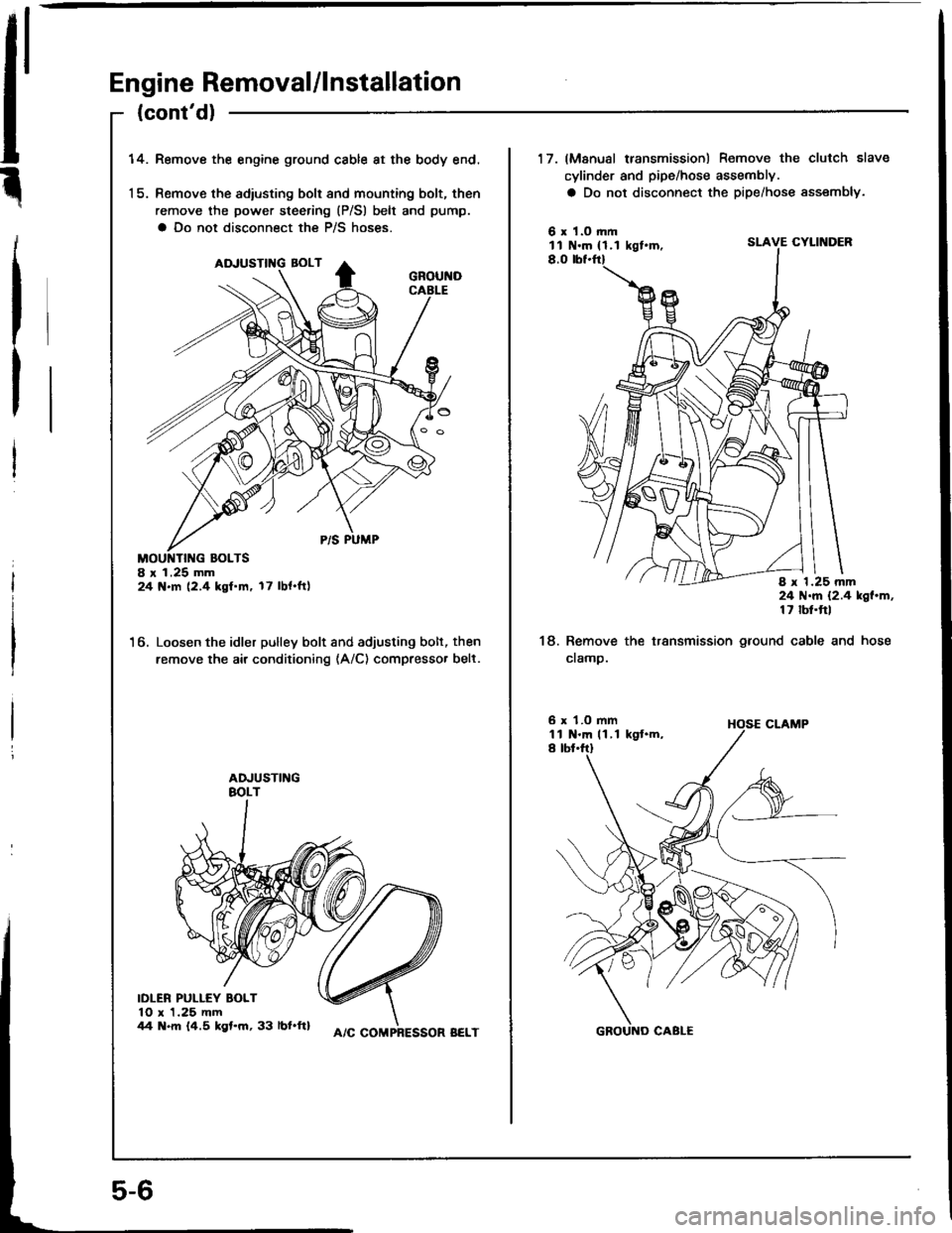
14.Remove the engine ground cable at the body end.
Remove the adiusting bolt and mounting bolt, then
remove the power steering (P/Sl belt and pump.
a Do not disconnect the P/S hoses.
8 r 1.25 mm24 N.m (2.4 kgf.m. 17 lbl.ftl
6. Loosen the idler pulley bolt and adjusting bolt, then
remove the air conditioning (A/C) compresso. belt.
IDLER PULLEY BOLT10 x 1.25 mm44 N.m 14.5 kgt.m, 33 lbl.ftl
5-6
A/C COMPRESSOR BELT
17. (Manusl transmission) Remove the clutch slave
cylinder and pipe/hose assembly.
a Do not disconnect the pipe/hose assembly.
6 x 1.O rl|mll N.m { 1.1 kgt.m,SLAVE CYLINDER
8.0
8 x 1.25 mm24 N.m {2.4 kgl.m,17 lbt.ftl
18. Remove the transmission ground cable and hose
cramp.
6 x 1.O mm1l N.m 11 ,1 kgt.m,I tbt.ftl
Page 80 of 1413
Cylinder Head
Removal (cont'dlI
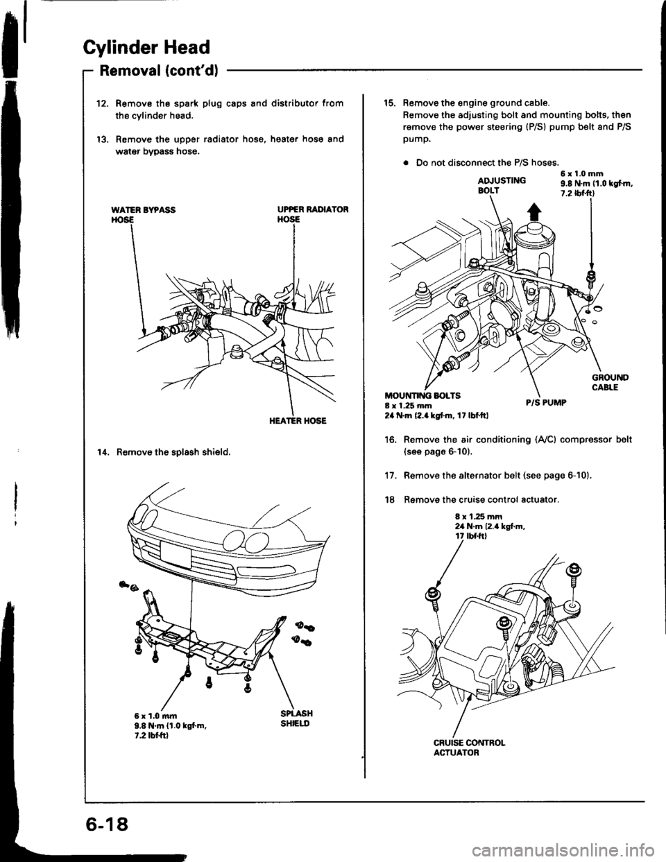
12.R€move the spark plug caps and distributor from
the cvlinder head.
Remove the upper radiator hose, heater hose and
water bypass hose.
UPPER RAI'IAYOR
14. Remove th6 solash shield.
WATER BYPASS
9.8 N.m {1.0 kgt m.t.2 tbr.frt
sHtEut
15. Remove the engine ground cable.
Remove the adjusting bolt and mounting bolts, then
remove the power steering (P/S) pump belt 8nd P/S
pump.
. Do not disconnect the P/S hoses.
6x1.0mmADJUSTINGBOLT9.8 N.m 11.0 tgfm,7.2 tbf.ftl
8 x 1.25 mm24 .m (2.akstm, 17lbf.ftl
P/S PUMP
Remov€ the air conditioning (Ay'Cl compressor(see pags 6-10).
R€move the alternator belt (see page 6-10).
Ramove the cruise control actuator.
8 x 1.25 mm2a N.m 12.4 kgt m,
belt
17.
t8
ACTUATOR
Page 99 of 1413
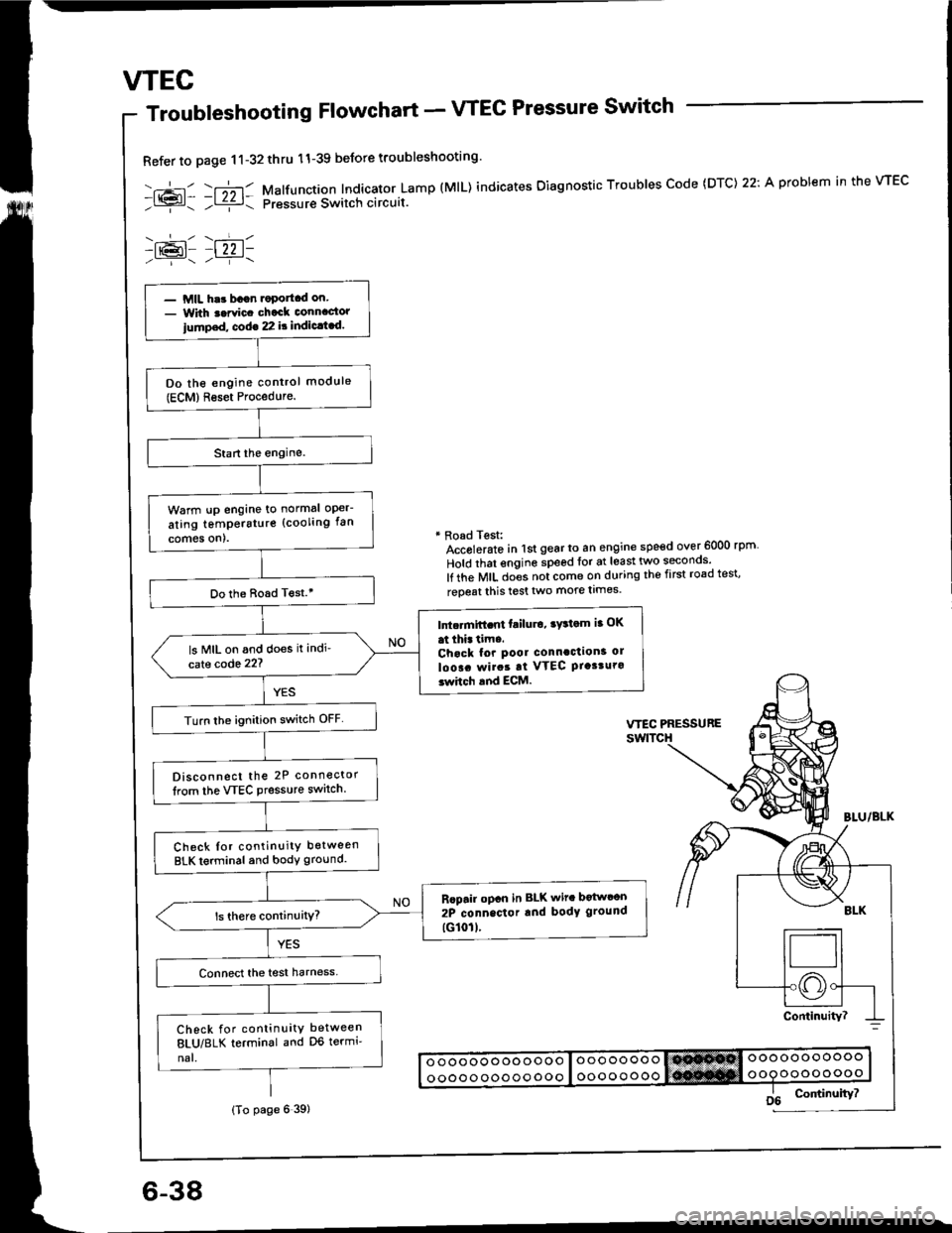
wEc
6-38
Troubleshooting Flowchart - VTEC Pressure Switch
Refer to page 11-32thru 11-39 beJore troubleshooting'
-.+- -r";-r- Malfunction Indicator Lamp (MlL) indicates Oiagnostic Troubles Code (DTC) 22: A problem in the VTEC- l{{?l- ;l ziz r: pressur€ Switch circuit.
-lr@l- |22 1-
* Road Test:Accolerato in lst gear to an engine speed over 6000 rpm
Hold that engine speed for at least two seconos'
lf the MIL does not come on during the first road test'
reoeat this test two more limes.
- MIL har bagn.oportcd on.- With t.rvic. chack connactor
iump.d, cod€ 22 it indic.t.d.
Do the engine control module(ECM)Reset Procedure.
Warm !p engine to normal oper-
ating temperstur€ (cooling fan
comes on).
Do the Boad T€st.'
Intc.mift.nt failu.o, ry3tom ia OK
at thi. tim..Chack for pool connaction3 ol
loo!. rvirat at VTEC Ptasturo3whch and ECM.
ls MIL on and does it indi'
cate code 22?
Turn lhe ignition switch OFF
Disconnect the 2P connector
lrom the VTEC Pressure switch.
Check Ior continuity between
BLK terminal and body ground.
Rcpair opcn in BLK wit. botwcon
2P connector rnd body ground
tG101l.
Check for continuity between
8LU/8LK terminal and D6 termi'
nal.
(To page 6 39)
Page 100 of 1413
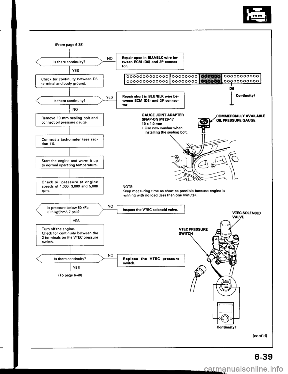
(From page 6-38)
Ropair op€n in BLU/BLK $,iro between ECM lD6) and 2P conn.c-tor,
Check for continuity between D6terminal and body ground.
R6pri. short in BLU/BLK wir. bc-tweon ECM (D6l .nd 2P connec-toa,
Remove 10 mm sealing bolt andconnect orl pressure gauge.
Connect a tachometer {soe sec-tion 11).
Start the engine and warm it upto normal operatrng temperature.
Check oil pressure at enginespeeds of 1,000, 3,000 and 5,000rpm,
ls pressure bolow 50 kPa(0.5 kgflcm'�, 7 psi)?Inrpoct tho VTEC aolanoid v.lv..
Turn off the engine.Check lor continuity between the2 terminals on the VTEC pressure
switch.
o oooooo ooo ooo I oooooooo trt!*Hffi Oooooo ooooo
o oooo ooooo ooo I oo oooo ooo ooooo oo oo o
Coitlnuity?
D6
I
GAUGE JOINT ADAPTERSNAPON MT2&1710 x 1.0 mm. lJse new washer wheninstalling the sealing bolt.
Y AVAILAEIIOIL PRESSURE GAUGE
\-
]L
vtEc sot-€NotD
(cont'd)
NOTE:Keep mgasuring time as short as possible bocaus€ engine isrunning with no load (less than one minute).
YES
(To page 6-40)
Conlinuity?
6-39
Page 118 of 1413
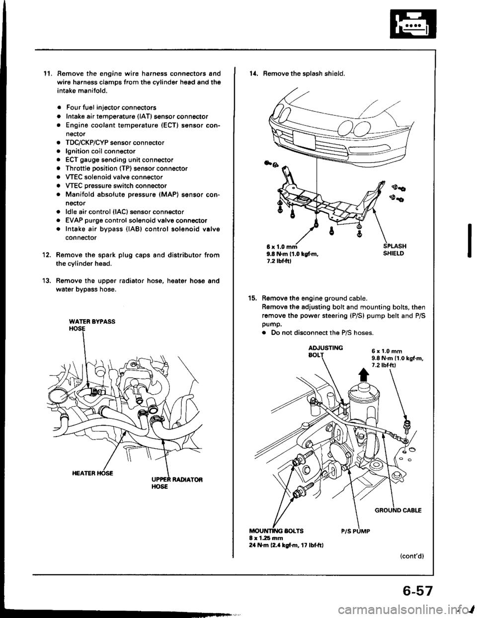
ll.Remove the engine wire harness connectors and
wi.e ha.ness clamps from the cylinder head and the
intake manitold.
Four fuel injector connectors
Intake air tempe.ature {lAT) sensor connector
Engine coolant temperature (ECT) sensor con-
nector
TDC/CKP/CYP sensor connector
lgnition coil conn€ctor
ECT gauge sending unit connector
Throttle position (TP) sensor connector
VTEC solenoid valve connector
VTEC Dressure switch connector
Manifold absolute pressure (MAP) sensor con-
nector
ldle air control {lAC) sensor connector
EVAP purge controlsol€noid valvo connector
Intake air bypass {lABl control solenoid valve
conneclor
a
o
a
o
a
a
a
a
a
a
a
a
a
12.
13.
Remove the spsrk plug caps and distributor from
the cylinder head.
Remove the upper radiator hose, heat€r hose and
water bypass hose.
WATER BYPASS
HOSE
6r1.0mm9.8 N.m (1.0 kgt m,1.2 tbtftl
14. Remove the sDlash shield.
Remove the engine ground cable.
Romovo the adjusting bolt and mounting bolts, then
remove the power steering (P/S) pump belt and P/Spump.
. Do not disconnect the P/S hoses.
(cont'dl
15.
6x1.0mm9.8 N.m 11.0 kgl.m,7.2 tbt.ttl
6-57
,l
Page 171 of 1413
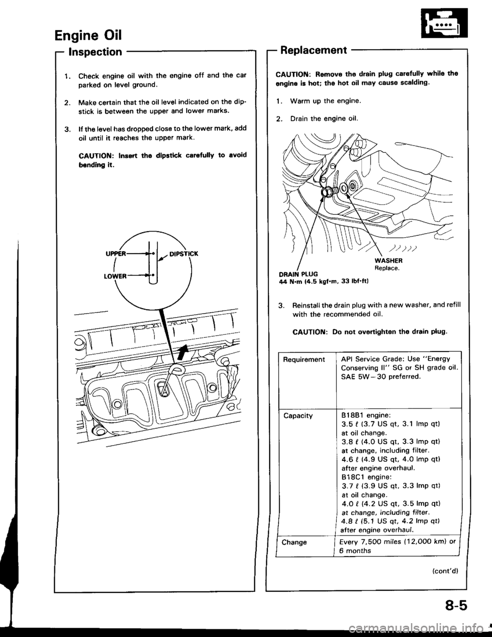
Engine Oil
lnspection
Check engine oil with the engine off and ths cal
parked on level ground,
Make cenain that the oil level indicated on the dip-
stick is between the upper and lower marks.
lf the l€vel has dropped close to the lower mark, add
oil until it reaches the upper mark.
CAUTION: Inssrt lho dipstick carotully to avoid
bending it.
3.
Replacement
CAUTION: Remova tho drain plug cal€fully whilo the
ongine is hot; the hot oil may cause scalding.
1. Warm up the engine.
2, Drain the engine oil.
3. Reinslallthe drain plug with a new washer, and refill
with the recommended oil.
CAUTION: Do not ovortighton tho drain plug.
(cont'd)
RequirementAPI Service Grade: Use "Energy
Conserving ll" SG or SH grade oil.
SAE 5W-3O Drefered.
CapacityB18B1 engine:
3.51 (3.7 US qt, 3.1 lmp qtl
at oil change.
3.8 t (4.0 US qt, 3.3 lmp qt)
at change. including filter.
4.6 I 14.9 US qt. 4.0 lmp qt)
after engine overhaul.
B18Cl engine:
3.7 f (3.9 US qt, 3.3 lmp qt)
at oil change.
4.O t 14.2 US qt, 3.5 lmp qt)
at change, including filter.
4.a I (5.1 US qt, 4.2 lmp qt)
after engine overhaul.
ChangeEvery 7,5OO miles (12,OOo km) or
6 months
8-5
Page 231 of 1413
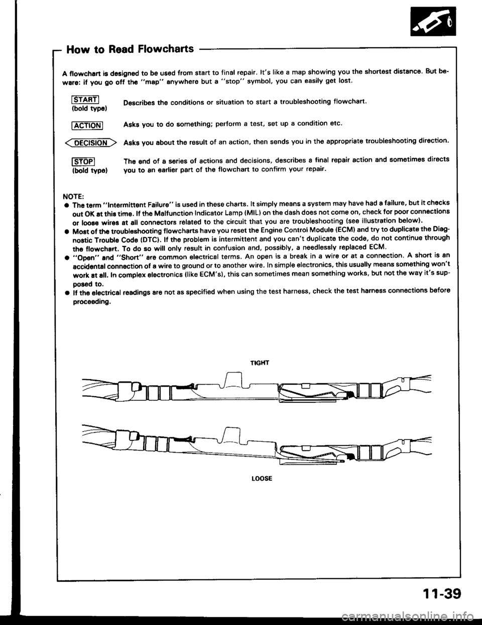
How to Read Flowcharts
A flowchrrt is dasigned to be us€d fiom start to final repair. lt's like a map showing you the shortest distanco. But be-
ware: if you go off tho "map" anywhere but a "stop" symbol, you can easily get lost
l6rffil Desclibas the conditions or situation to start a troubleshooting flowchart.(bold tyDo)
|TeTiONl Asks you to do something; pedorm a test, set up a condition etc'
<:6Eei6io-fr\> Asks you about the result of an action, then sends you in the appropriste troubleshooting direction.
I-SJTFI The snd of a series ot actions and decisions, describes I tinal repair action and aomotimea diracts
(bold typel you to 8n garlier part of the tlowchart to confirm your repair'
NOTE:
a Tha tarm ,,lntormittgnt Failure" is used in these chans. lt simply means a system may have had a failur6, but it chocks
out OK !t this time. lf th6 Msltunction Indicator Lamp (MlL) on ihe dash does not come on, check for poor connections
or loose wires at all connectors rolated to the cilcuit that you are troubleshooting (see illustration b6low).
a Most ot tho troublashooting flowchans have you reset the Engine Control Module (ECM) and try to duplicate the Disg-
nostic Troubls Cod6 (DTC). lf the problem is intermittent and you c8n't duplicat€ the cod6, do not continus through
the flowchart, To do so will only rosult in confusion and, possibly, a ne€dlessly replaced ECM
a ,,opon,'and ,,short,, are common electrical terms. An open is a break in a wir6 or at a conn€ction. A short is an
accidontal connaction ot a wir€ to ground or to another wire. In simple electronics, this usually means som€thing won't
work at all. In complex electronics (like ECM's), this can sometimes mean something wolks, but not the way it's sup-
poSad to,
a il th6 olectricsl readings are not as specified when using the test harness, check the test harness connoctions bsfore
procooding.
LOOSE
11-39