exhaust pipe b HONDA INTEGRA 1994 4.G Workshop Manual
[x] Cancel search | Manufacturer: HONDA, Model Year: 1994, Model line: INTEGRA, Model: HONDA INTEGRA 1994 4.GPages: 1413, PDF Size: 37.94 MB
Page 53 of 1413
*l
Engine Removal/lnstallation
(cont'dl
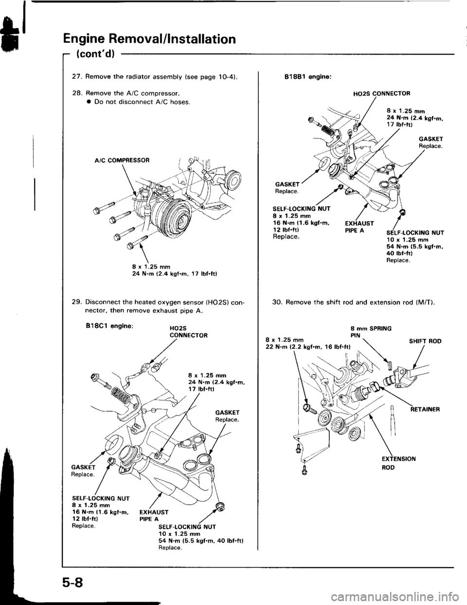
27. Remove the radiator assembly {see page 1O-4),
28. Remove the A/C compressor.
a Do not disconnect A/C hoses.
8 x '1.25 mm24 N.m t2.4 kgf.m, 17 lbl.ftl
29. Disconnect the heated oxygen sensor (HO2Sl con-nector, then remove exhaust pipe A.
B'l8Cl engine: Ho2s
I x 1.25 mm24 N.m (2.4 kgf.m,17 rbt.ftt
Replace.
SELF-LOCKING NUT8 x 1.25 mm16 N.m 11.6 kgf.m,12 tbl.ftlReplace.
EXHAUSTPIPE A
SELF10 x 1.25 mm54 N.m (5.5 ksf.m.4O lbf'ltlReplace.
CONNECTOR
5-8
8188l engine:
8 x 1.25 mm24 N.m 12.4 kgf.m,17 tbt.trl
GASKETReplace.
GASKETReplace.
SELF.LOCKING NUTI x 1.25 mm16 N.m (1.6 kgt.m,12 tbf.ft)Replace.10 x 1.25 mm54 N.m (5.5 kgl.m,40 tbt.ttlReplace.
30. Remove the shift rod and extension rod {M/T).
I x 1.25 mm22 N-m 12.2 kgf.m, '16 lbf.ftlSHIFT ROD
Page 179 of 1413
lntake Manifold/Exhaust System
Intake Manifold
Replacement ............................... 9-2
Exhaust Manifold
Replacement ............................... 9-4
Exhaust Pipe and Muffler
Replacement ............................... 9-5
Page 183 of 1413
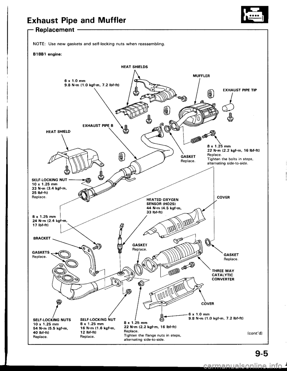
Exhaust Pipe and Muffler
Replacement
NOTE: Use new gaskets and
Bl88l engine:
selflocking nuts when reassembling.
HEAT SHIELDS
6 x 1.0 mm9.8 N.m l1.O kgf.m, 7.2 lbf.ftl
HEAT SHI€LD
SELF-LOCKIIIG NUT
,@\
10 x 1.25 mm33 N.m (3.4 kgt.m,25 tbf.fttReplace.HEATEO OXYGENSENSOR (HO2Sl
44 N.m 14.5 kgt.m,33 rbf.ftlI x 1.25 mm24 N.m 12.4 kgf.m,17 tbl.frl
BRACKET
GASKETSReplace.
SELF-LOCKING NUTS10 x 1,25 mm54 N'm 15.5 kgf'm,40 tbf.ftlReplace.
SELF-LOCKING NUT8 x 1.25 mm16 N.m {1.6 kgf.m,r2 tbt.frlReplace.
I x 1.25 mm22 N.m (2.2 kgl.m, r6lbt.ftlReplace.Tighten the flange nuts in steps,alternating side-to-side.
MUFFLER
EXHAUST
I,
^1
e
e
8 x 1.25 mm22 N.m 12.2 kgt.m, 16 lbf.ftlReplace.Tighten the bolts in steps,alternating side-to-side.
COVER
GASKETReplace.
THREE WAYCATALYTICCONVERTER
COVER
6 x 1.0 mm9.8 N.m l1.O kgf.m, 7.2 lbl.ttl
PIPE TIP
(cont'd)
Page 184 of 1413
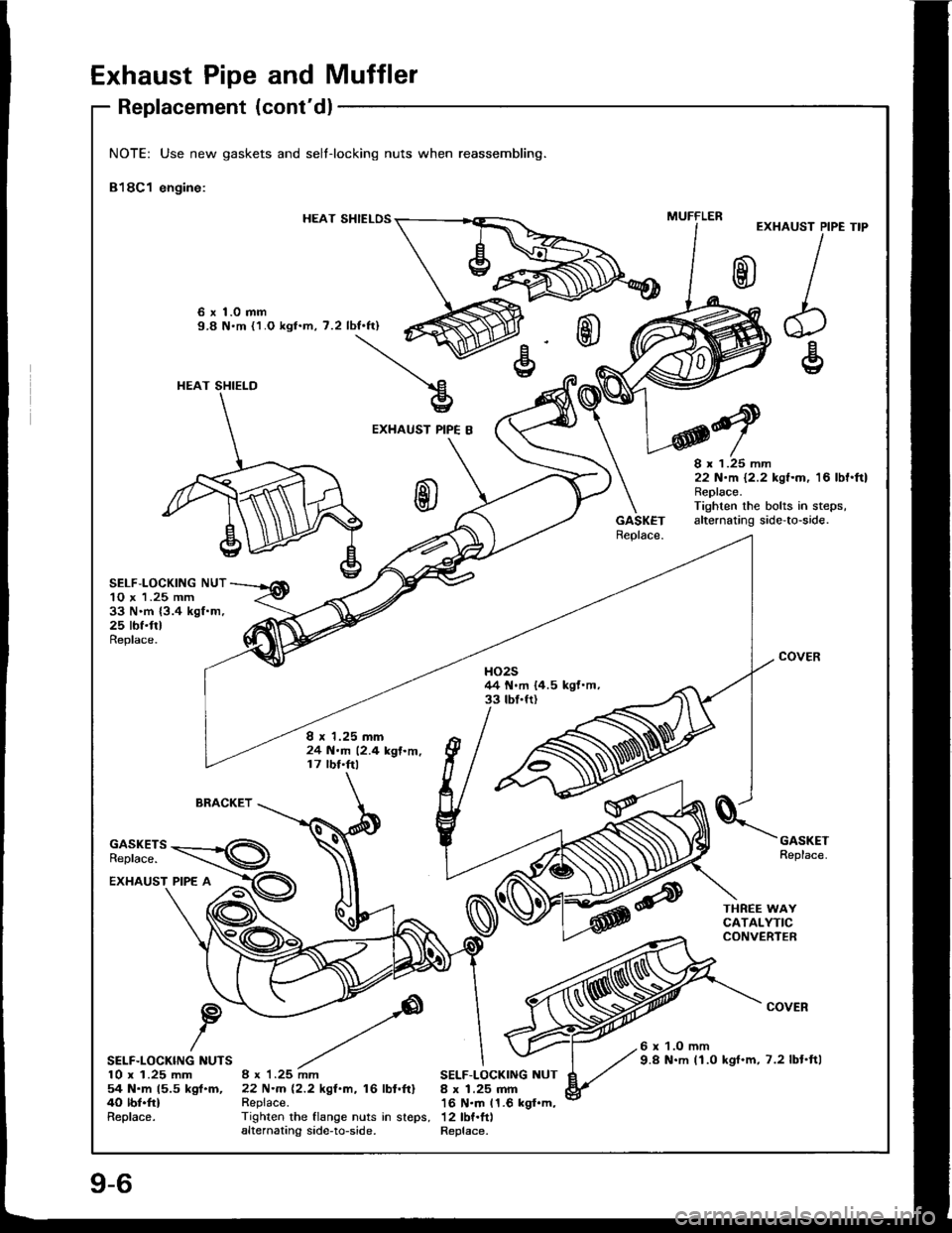
Exhaust Pipe and Muffler
Replacement (cont'dl
NOTE: Use new gaskets and selt-locking nuts when reassembling.
818C1 engine:
HEAT SHIELOSEXHAUST PIPE
I
h€
TIP
6 x 1.0 mm9.8 N'm {1.O kgt.m, 7.2 lbf.ft)
EXHAUST PIPE B
GASKETReplace.
8 x 1.25 mm22 N.m 12.2 kgf.m, 16 lbf'ftlReplace.Tighten the bolts in steps,alternating side'to-side.
SELF,LOCKING NUT10 x 1.25 mm33 N.m {3.4 kgf.m,25 tbf.frlReplace.
COVERHO2544 N.m {4.5 kgf.m,33 tbf.fr)
I r 1.25 mm24 N.m 12.4 kgf.m,17 lbf.ftl
BRACKET
GASKETSReplace.
GASKETReplace.
EXHAUST PIPE A
COVER
SELF.LOCKING NUTS10 x 1.25 mm54 N.m 15.5 kgl.m,40 lbf.frlReplace.
6 x 1.O mm9.8 N.m (1.0 kgf.m, 7.2 lbt'ft|8 x 1.25 mm22 N.m 12.2 kgf.m, 16 lbl.ftlRepiace.
SELF-LOCKING NUT8 x 1.25 mm16 N.m 11.6 kgf.m,Tighlen rhe flange nuts in sreps, 12lbf.ftlalternating side-to-side. Replace.
MUFFLER
HEAT SHIELD
Page 238 of 1413
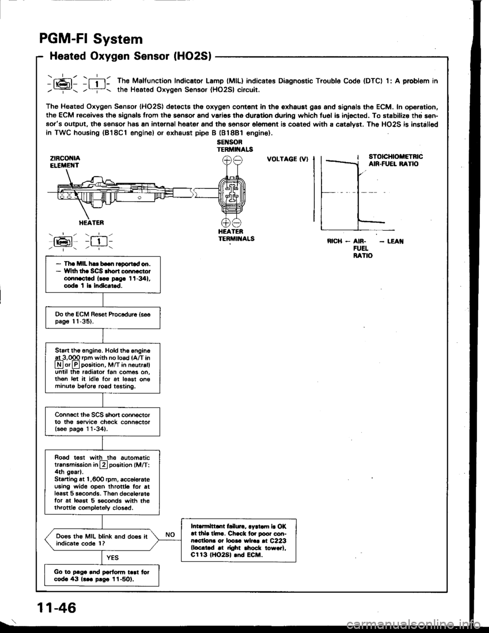
PGM-FI System
Heated Oxygen Sensor lHO2Sl
ztRcot{lAELEiIE'{T
HEATER
- --.'!- - -__-
lrPl _l !l-
-fi-l: The Malfunction Indicator Lamp (MlL) indicates Diagnostic Troubls Code (DTC) 1: A problsm in
/? the Heated Oxygen Sonsor (HO2S| circuit.
The Heated Oxygen Sensor IHO2S) det€cts th6 oxygon contont in th6 exhaust gas and signals th6 ECM. In operation,
the ECM receiv€s th6 signals trom the sensor and vari€s the duration during which tu6l is iniocted. To stabilize thd sen-aor's output, tho sensor has 8n intarnal heater and the sensor olemant is coatod with a catslyst. The HO2S is installod
in TWC housing (B18Cl engine) or exhaust pipe B (Bl8Bl €ngine).
sEl{SORTERMII{ALS
:tz-t6l-/ --.- \
VOLTAGE (V}sTotcHtoltETncAIR-FUEL BANO
HEATEBTEBMIT{ALSRICH - AN. - LEAI{FUELRATIO- Th! mll h.. bo.n raportad on.- Wlth thr SCS rhon coon cto.connoctad lr.. p!9. 1t-341,cod. t l. Indlcltrd.
Oo th€ ECM Res€t Procodure {soopag€ 11-35).
Stan the 6ngine. Hold th6 engine
A3,qgq rpm with no load {A/T in
Lryl or lll position, M/T in nourralluntil the radiator lan com6s on.then lot it idle lor ot least on6minutg beforo road t€6tin0.
Connoct ths SCS short connoctorto th6 sorvic€ check connectorlsoo p.g6 1 1-34).
Rood t€st witlthe automatictransmission in L?l position (M/T:4th gear).Stsrting st l,600 rpm, acc6lorateu6ing wide open throttlo for atlesgt 5 seconds. Thsn dgcol€rstefor at lorst 5 s€conds with th€throttlo completoly closed.
Intarmittd[ t llurc, lyri.m b Of!l thla tlmc. Ch.ck lor poor con-nacdona o? loota wlrat |l C223(loc.trd at right $ock towo.l,Cr 13 (HO2S| lnd ECM.
Ooes the MIL blink and doos itindic6t6 cod6 1?
Go to plga and partonn tad fotcod. 43 lr.a p.go l1-501.
1 1-46
Page 347 of 1413
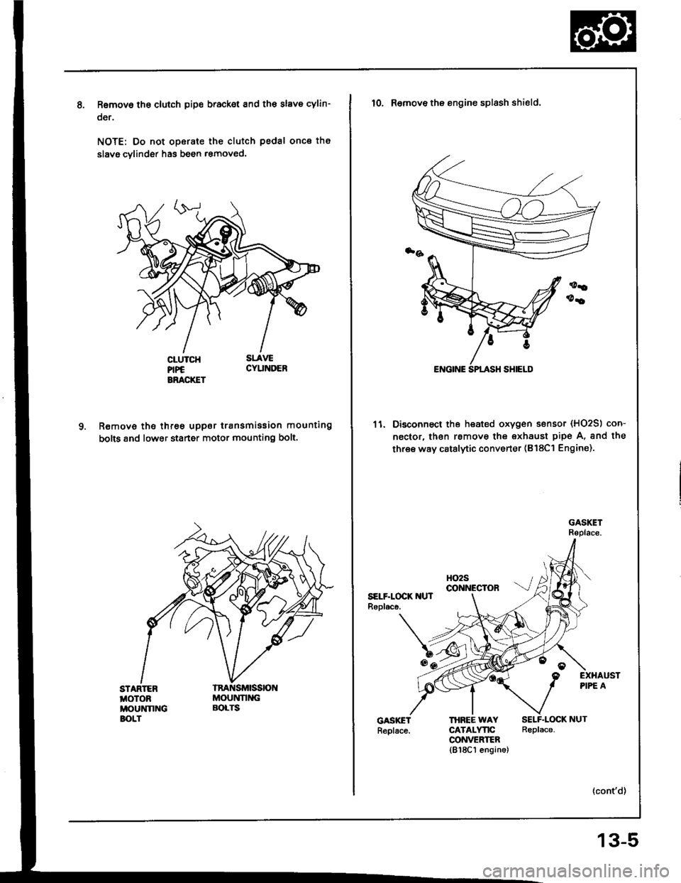
Removo tho clutch pip€ bracket and th€ slave cylin-
oer.
NOTE: Do not operate the clutch pedal once th€
slavg cvlinder has been r€moved.
R€move the three uppor transmission mounting
bolts 8nd lower staner motor mounting bolt.
STARTEBMOTOBMOUNNNGBOLT
MOUNNNGBOLTS
10. Remove the engine splash shield.
11. Disconnect the heated oxygen sensor (HO2S) con-
nector, lhsn rsmove the exhaust pipe A, and the
three way catalytic converter (B18Cl Engine).
HO2Sco NEctoRSELF.LOCK IIUTRopl.ce.
EXHAUSTPIPE A
THBEE WAYCATALYTICCONVEEIER1818C1 engin6)
SELF.LOCK NUTReplace.
13-5
Page 390 of 1413
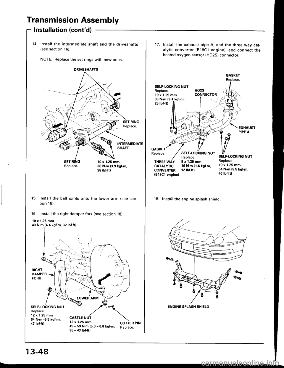
Transmission Assembly
14. Install the intermediate shaft and the driveshafts(see section 16)-
NOTE: Replace the set rings with new ones.
Installation (cont'd)
-Sl
SET RINGReplace.
INTERMEDIATESHAFT
Replace.10 x 1.25 mm38 N.m (3.9 kgt m,28 tbtft)
15. Install the ball joints onto the lower arm (see sec-
tion 18).
16. Install the right damper fork (see section 18).
10 x 1.25 mm43 N.m {4.o ksf.m.32 lbf.ft)
RIGHTDAMPERFOBK
SELF.LOCKING NUTReplace.12 x 1.25 mm64 N.m {6.5 kgf.m,47 tbtft)
tLOWER ARM
:\
COTTER PIN
CASTLE NUT12 x 1.25 mm49 - 59 N.m 15.0 - 6.0 kgf m. Reptace.36 - 43 tbf.frl
13-44
DNIVESHAFTS
::.t
L
17. lnstall the exhaust pipe A, and the three way cat-
alytic converter (Bl8C'1 engine), and connect theheated oxygen sensor (HO2S) connector.
SELF-LOCKING NUTHO2SCONNECTORReplace.10 x 1.25 mm33 N.m (3.4 kgt.m,2s tbtftt
GASKETReplace.SELF.LOCKING NUTReplace.8 x 1.25 mm
SELF.LOCKING NUTReplace.THREE WAYCATALYTICCONVERTER1818C'l enginel
16 N'm 11.6 kgt m, 10 x 1 25 mm
l2tbt.ftl 54 N.m 15.5 kgt m,iro lbf.ftl
18. Install the engine splash shield.
GASKET
Page 479 of 1413
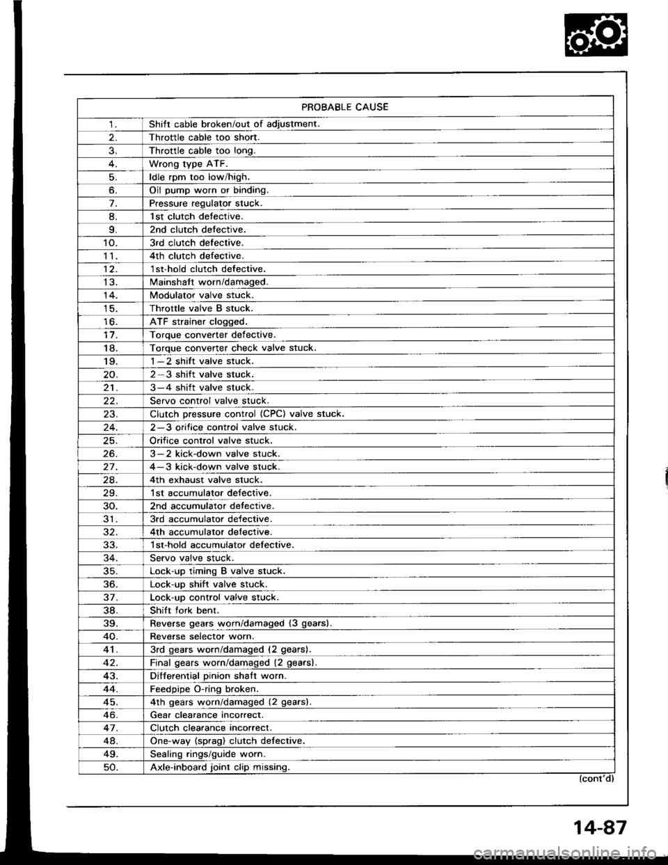
PROBABLE CAUSE
1Shitt cable broken/out of adiustment.
Throttle cable too short.
Throttle cable too long.
Wrong type ATF.
ldle rpm too low/high.
o.Oil pump worn or binding.
7.Pressure regulator stuck.
8.l st clutch detective.
9.2nd clutch detective.
10.3rd clutch defective.
114th clutch defective.
12.1 st'hold clutch defective.
13.Mainshatt worn/damaged.
14.Modulator valve stuck.
Throttle valve B stuck.
lo.ATF strainer clogged.
Toroue converter def ective.
18.Torque converter check valve stuck.'I 9.1-2 shift valve stuck.
2-3 shift valve stuck.
213-4 shift valve stuck.
Servo control valve stuck.
23.Clutch Dressure control (CPC) valve stuck.
2-3 orifice control valve stuck.
Orifice control valve stuck.
26.3-2 kick-down valve stuck.
27.4-3 kick-down valve stuck.
24.4th exhaust valve stuck.
29.1st accumulator detective.
30.2nd accumulator detective.
313rd accumulator defective.
4th accumulator defective.
1 st-hold accumulator defective.
Servo valve stuck.
35.Lock-up timing B valve stuck.
36.Lock-up shift valve stuck.
37.Lock-uo control valve stuck.
38.Shift fork benr.
39.Reverse gears worn/damaged (3 gears).
40.Reverse selectot worn.
413rd gears worn/damaged (2 gears).
Final qears worn/damaged (2 gearsl.
43.Differential Dinion shatt worn.
44.Feedpipe O-ring broken.
45.4th qears worn/damaged (2 gearsl
Gear clearance incorrect.
47.Clutch clearance incorrect.
48.One-way (sprag) clutch defective.
49.Sealinq rings/quide worn.
50.Axle-inboard joint clip missing.
Page 493 of 1413
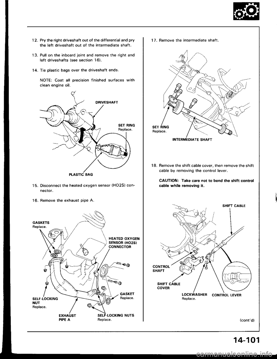
1 2. Pry the right driveshaft out of the differential and pry
the lett driveshatt out of the intermediate shaft.
'13. Pull on the inboard joint and remove the right and
left driveshafts (see section 16).
'14. Tie plastic bags over the driveshaft ends.
NOTE: Coat all precision finished surfaces with
clean engine oil.
PLASTIC BAG
Disconnect the heated oxygen sensor (HO2S) con-
necror.
Remove the exhaust pipe A.16.
SELF-LOCKINGNUTReplace.
Replace.
14-101
17. Remove the intermediate shaft.
Remove the shift cable cover, then remove the shift
cable by removing the control lever.
CAUTION: Take care not to bend the shift control
cabls whilo removing it.
18.
SHIFT CABLE
LOCKWASHER CONTROLLEVERReplace.
(cont'dl
Page 556 of 1413
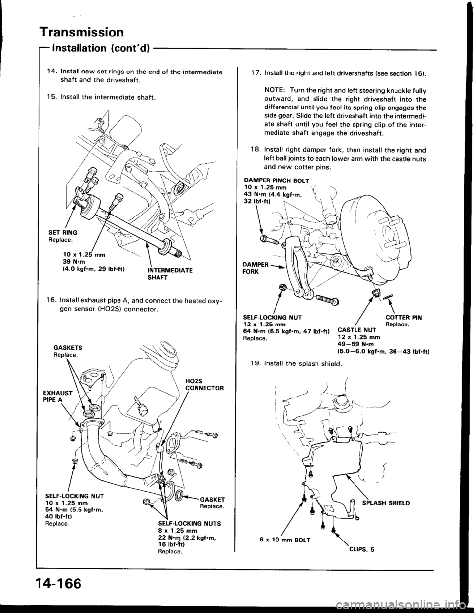
Transmission
Installation {cont'd)
14.
15.
Install new set rings on the end of the intermediate
shaft and the driveshaft.
Install the intermediate shaft.
SET RINGBeplace.
16.
10 x 139 N.m14.O kgf.m, 29 lbf.ftl
Install exhaust pipe A. and connect the heated oxv-gen sensor {HO2S) connector.
SELF-LOCKING NUT10 x 1.25 mm54 N.m (5.5 kgl.m,40 rbt.trlReplace.
GASKETReplace.
SELF.LOCKING NUTSI x 1.25 mm22 N.m 12.2 kgl'n,16 lbt.trlRepl6ce.
SHAFT
14-166
DAMPER PINCH BOLT10 x 1.25 mm43 N.m 14.4 kgf.m,32 tbr.ftl
1 7. Install the right and left drivershafts (see section l6l.
NOTE: Turn the right and left steering knuckle fullyoutward, and slide the right driveshaft into the
differential until you feel its spring clip engages theside geaf. Slide the left driveshaft into the intermedi-
ate shaft until you teel the spring clip of the inter-mediate shaft engage the driveshaft.
18. Install right damper fork, then install the right andlett balljoints to each lower arm with the castle nuts
and new cotter Dins.
\
COTTERReplace.CASTLE NUT12 x 1.25 mm49-59 N.m{5.O-6.0 ksf.m, 36-43
SELF.LOCKING NUT12 x 1 .25 mm64 N.m (6.5 kgl.h, 47 lbt.ftlReplace.
rbt'ft1
19. Install the splash shield.
6 x 10 mm BOLT
cltPs, 5