fuse box diagram HONDA INTEGRA 1994 4.G Workshop Manual
[x] Cancel search | Manufacturer: HONDA, Model Year: 1994, Model line: INTEGRA, Model: HONDA INTEGRA 1994 4.GPages: 1413, PDF Size: 37.94 MB
Page 608 of 1413
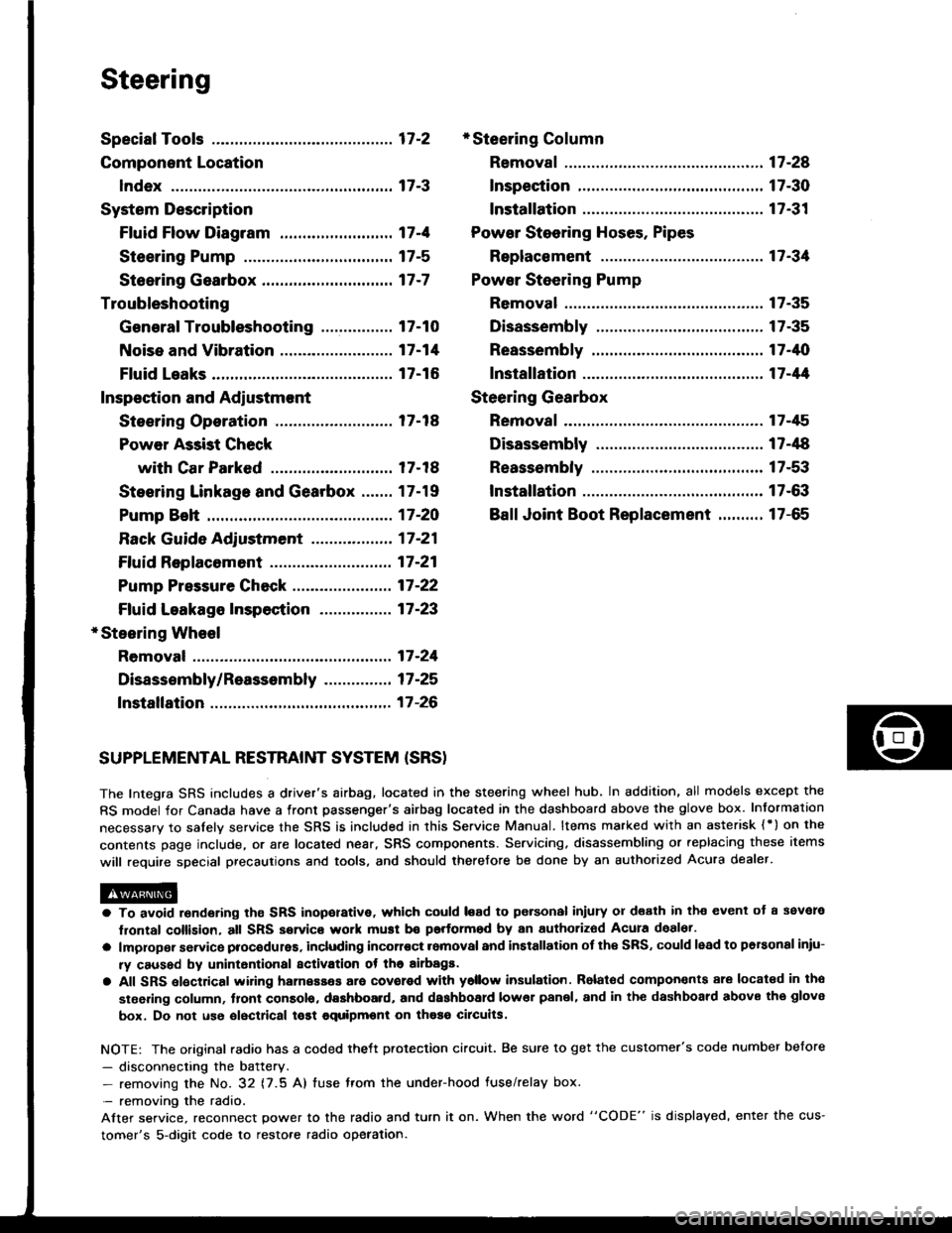
Steering
Special Tools ............. 17-2
Component Location
lndex ................ ...... 17-3
System Description
Ff uid Flow Diagram ......................... 17 -1
Steering Pump ................................. 17-5
Steering Gearbox ............................. 17-7
Troubleshooting
General Troubleshooting ................ 17-10
Noise and Vibration ......................... 17-14
Fluid Leaks ............. 17-16
Inspection and Adiustment
Steoring Operation .......................... 17 -14
Power Assist Check
with Car Parked ........................... 17-18
Steering Linkage and Gearbox ....... 17-19
Pump Beh .............. 17-20
Rack Guide Adjustment ............. ..... 17-21
Ff uid Replacement ...................... ..... 17 -21
Pump Pressure Check .................. .... 17 -22
Ffuid Leakage lnspection ................ 17-23
+ Steering Wheel
Removal ..,,,,,,,........ 17-24
Disassembly/Reassembly ............... 17 -25
fnstallation ,......,,,,,. 17-26
* Steering Column
Removaf .................17-28
Inspection .............. 17-30
Installation ............. 17-31
Power Steering Hoses. Pipes
Replacemont ......... 17-3tl
Power Steering Pump
Removal ................. 17-35
Disassembly .......... 17-35
Reassembly ........... 17-'10
lnstallation ........,..., l7-tltl
Steering Gearbox
Removaf .,.,............. 17-45
Disassembly .......... 17-/E
Reassembly ........... 17-53
lnstallation ............. 17-63
Ball Joint Boot Replacement .......... 17-65
SUPPLEMENTAL RESTRAINT SYSTEM {SRSI
The Integra SRS includes a driver's airbag. located in the steering wheel hub, In addition, all models except the
RS model for Canada have a front passenger's airbag located in the dashboard above the glove box. Information
necessarv to safely service the SRS is included in this Service Manual. ltems marked with an asterisk {') on the
contents page include, or are located near, SRS components. Servicing. disassembling or replacing these items
will require special precautions and tools, and should therefore be done by an authorized Acura dealer.
a To avoid rsndering ths SRS inoporative, which could load to po.sonal iniury 01 d€ath in th€ event ot a ssvare
lrontal collision, all SRS service work muat be performod by an authorizod Acura deal6t.
a lmploper service procodules. including incorloct romoval and installation of the SRS, could lead to personal iniu-
ry caused by unintontional activation ot the airbags.
a All SRS elsctdcal wiring harnesses ara covorod with ysllow insulation. Rolalod compon€nts 8re locatsd in tho
stse ng column, tront console, dashboard, and dashboard lower panel, and in the dashboard above the glove
box. Do not use oloctrical tost equipmoni on thosa cilcuits.
NOTE: The original radio has a coded thett protection circuit. Be sure to get the customer's code number before
- disconnecting the battery.- removing the No. 32 (7.5 A) tuse from the under-hood fuse/relay box.
- removing the radio.
Alter service, reconnect power to the radio and turn it on. When the word "CODE" is displayed' enter the cus-
tomer's 5-digit code to restore radio operation.
Page 1180 of 1413
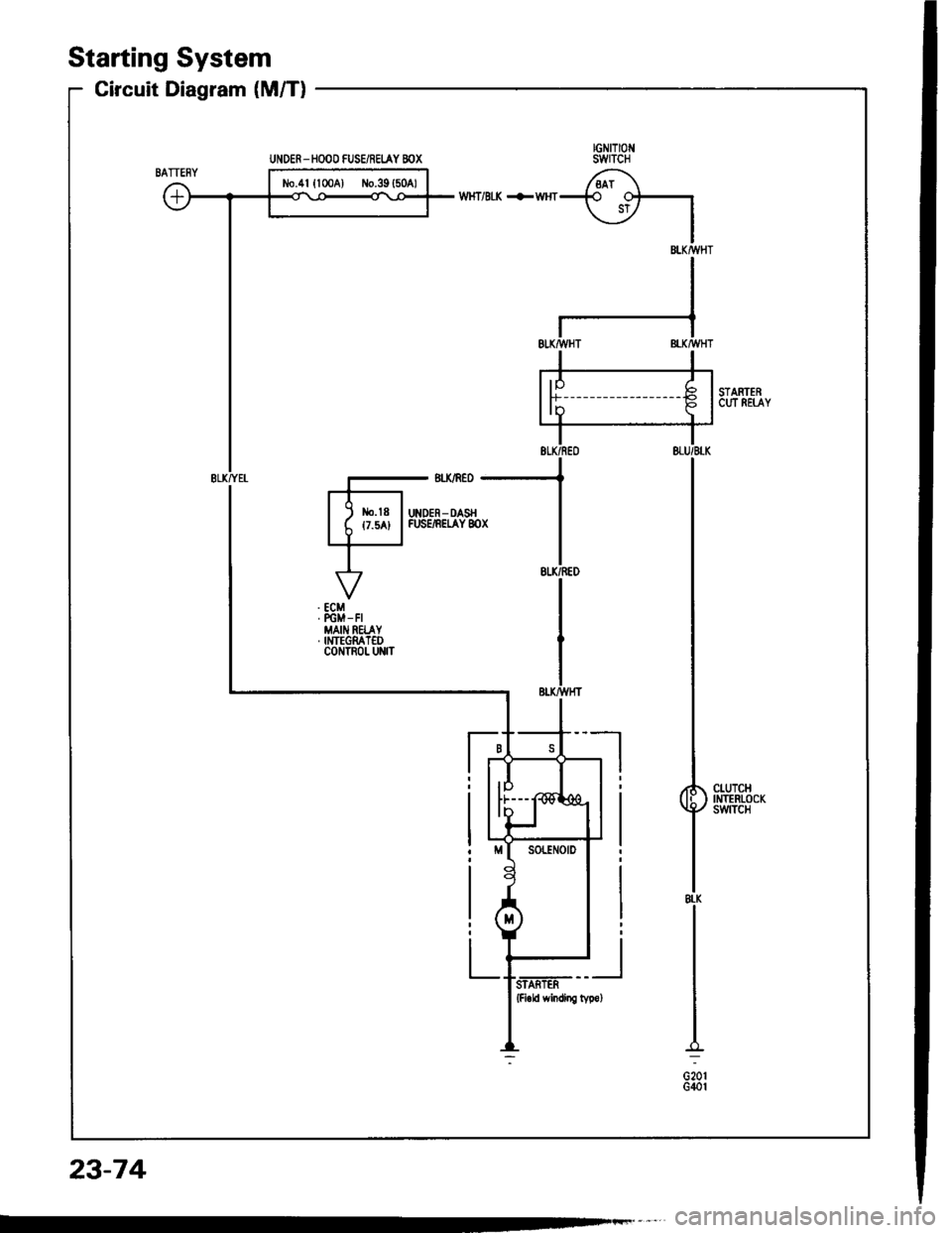
Gircuit Diagram (M/Tl
Starting System
tGNtTt0t{SWTCH
/.^1 +O OFr
\_:/ I
IBT.KMHT
STARTERCUT REIAY
I
I
t*u*
I8l-K
I
G20rG40r
IEUqWHT
rHlI STARTER
UNOER- HOOO FUSE/REI.AY BOX
Page 1181 of 1413
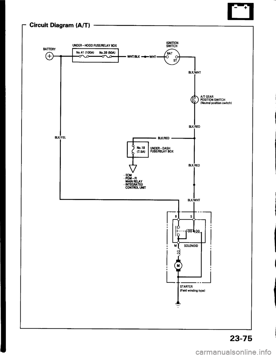
Circuit Diagram (A/T)
G?{raoswncH
6i\-{€ o+
\_v I
IBl-torvHT
II
I,(h A/I GEAR
g, ffi.:11?[:#ir11,",,
I
IBI.K/BED
UI{DER -HOOD FUSE/NEUY BOX
N,0.41 {l00Al Io.39160 t
Page 1194 of 1413
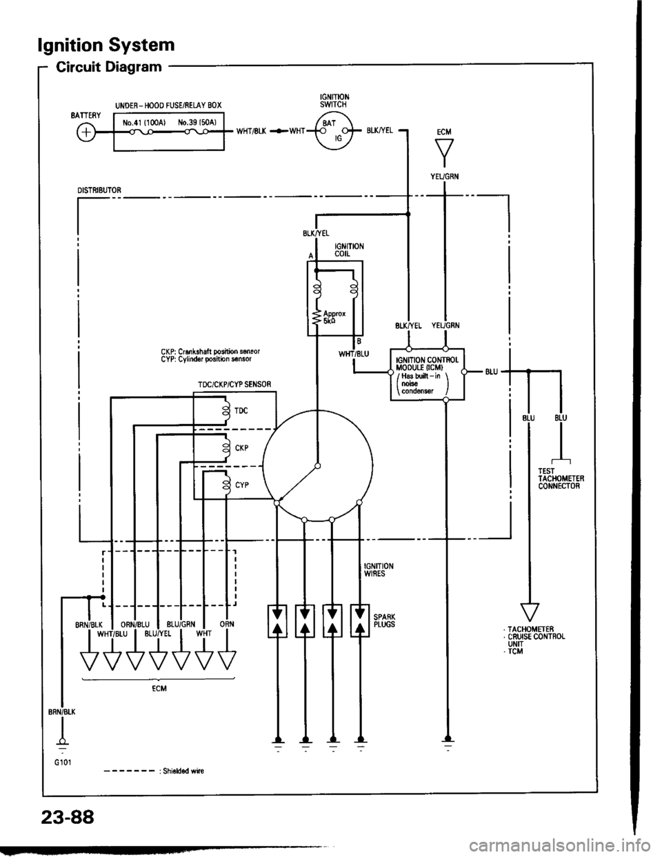
lgnition System
Circuit Diagram
CKP: Cr6nk.halt posilioo sonsorCYP| Cylindor position s€nsor
TOC/CKP/CYP SENSOR
-_r_1=__E
-J---L--L--Lr
ORN
U'+++
UNOER- HOOO FUSE/RELAY BOX
ECM
V
I
YEUGNiI
tG tTtoN c0NTROl-MoDUr.r (cMl
/ H8s built - in \I OOrsO I
23-88
Page 1217 of 1413
G FION SWIICH
No.41 l100Al No.39l50At
RAOIATORFANREI.AY
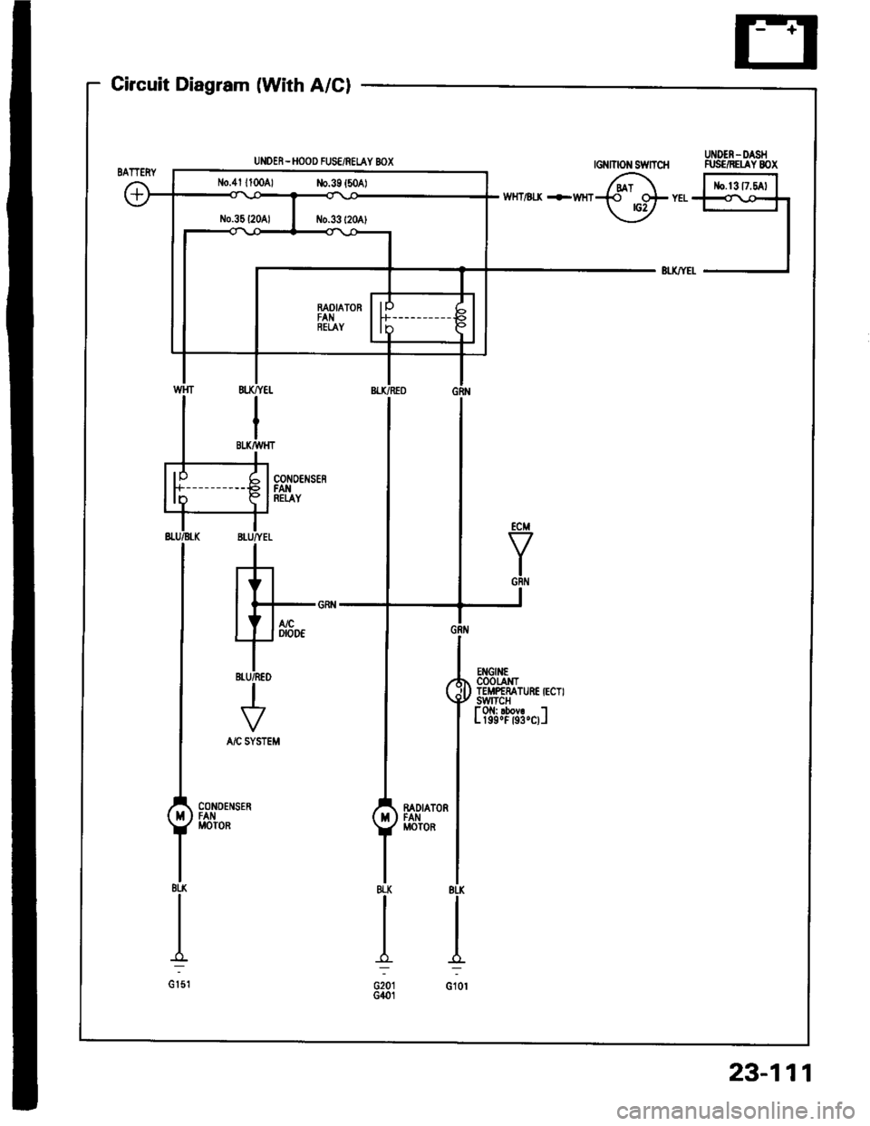
Gircuit Diagram (With A/Cl
UNOER - HOOO FUSE/REIAY BOX
,5
GRt{
| ,*n,n,,z*r CoOtAt{TqU llffffarunErEcrr
I
t?i'i."1",i:"ol
Imonron IFAN IMOTOR
I
IBI-K
I
I:
G10l
23-111
Page 1232 of 1413
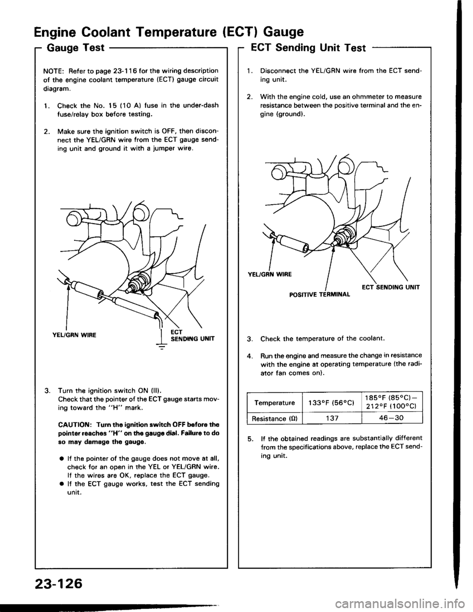
GaugeTest
NOTE: Refer to page 23-116 fot the wiring description
oJ the engine coolant temperature (ECT) gauge circuit
diagram.
1. Check the No. 15 (10 A) fuse in the under-dash
tuse/relay box before testing.
2. Make sure the ignition switch is OFF, then discon-
nect the YEL/GRN wire from the ECT gauge send-
ing unit and g.ound it with a jumper wire.
Turn the ignition switch ON (lll.
Check that the pointer of the ECT gauge starts mov-
ing toward the "H" mark,
CAUTION: Tuln th6 ignition switch OFF botore th€
point reaches "H" on tho gaugo dial. Failuro to do
so may damago tho gaugo.
a It the pointer of the gauge does not move at all,
check Jor an oDen in rhe YEL or YEL/GRN wire.
lf the wires are OK, replsce the ECT gauge.
a It the ECT gauge works, test the ECT sending
untt.
J.
Engine Coolant Temperature (ECTI Gauge
ECT Sending Unit Test
Disconnect the YEL/GRN wire from the ECT send-
ing unit.
With the engine cold, use an ohmmeter to measure
resistance between the positive terminal and the en-
gine (ground).
Check the temperature of the coolant.
Run the engine and measure the change in ,esistance
with the engine ai operating temperatu.e {the radi-
ator tan comes on).
5. ll the obtained readings are substantially different
Jrom the specifications above, replace the ECT send-
ing unit.
23-126
POSITIVE TERMINAL
Temperatu.e1330F (560C)185.F (850C)-
2120F (1000c)
Resistance (O)'t3746-30
Page 1246 of 1413
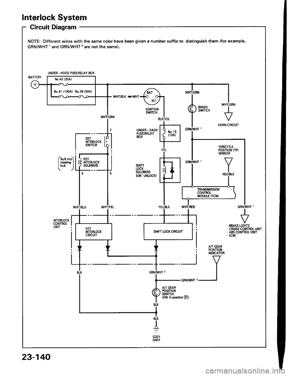
lnterlock System
Circuit Diagram
NOTE: Different wires with the same color have been given a number suffix to distinguish them (tor examplg,
GRNMHT 1 and GRNMHT 2 are not the same).
W}IT/BLK +WHT
Y I if,f,trfi
I i
^'v"'
IIN/vt,H] ,
I
l......................_GRNA,t/r{rz1
/r S'ftiei
f lJlT,ll*n""n,
UNOER -HOOD FUSE/REi.AY BOX
N0.41 (1OCA) No.39 l50A)
THROTTLEPOSITION ITPISENSOR
WHT/GRN
23-140
Page 1250 of 1413
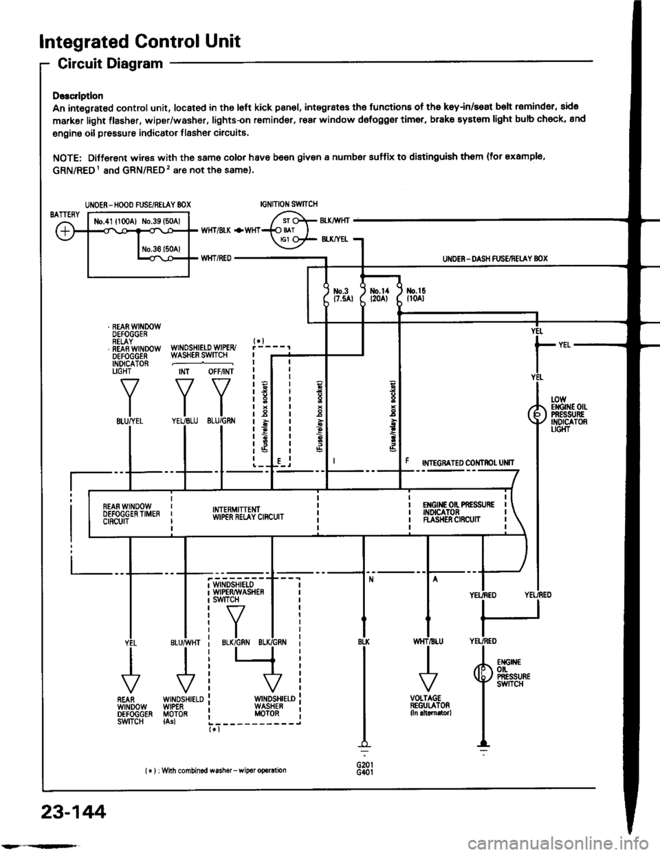
Integrated Control Unit
Circuit Diagram
D.3c ptlon
An integrat€d control unit, located in the left kick panel, integratss the functions of tho keyin/seat beh r6mind€r, sido
markar light {lasher, wiper/washer, lights-on r6minder, rear window dsfogger timer, brak€ system light bulb check, and
enging oil pressure indicator flasher circuitE,
NOTE: Difforent wires with the same color have be6n given a numbor suffix to distinguish them (for Example,
GRN/RED1 and GRN/RED'� are not the same).
WNOSHIELD WIPER/WASHER SWITCH
IMT OFFiINT
I
II
IIIIIIIIIIII
YEUEE
rl
t
P
UNOER - DASH FUS€/RETAY BOX
r NTEGRATED COI{TROI UNIT
t-0wErGrilE 0|lPRESSI'REINDICATORLIGI{T
WINDSHIELOWIPERAVASHERswtTcH
tr-/
IBLK/GRN BI
WINDSHIELOWIPERMOTOR{Asl
VOLTAGEREGULATOR{ln ahamator,
UNOER- HOOD FUSE/RELAY 8OX
I
r3
r8relit;rBt5I
23-144
lr ) : With combinod washef-wip€r oporation
Page 1285 of 1413
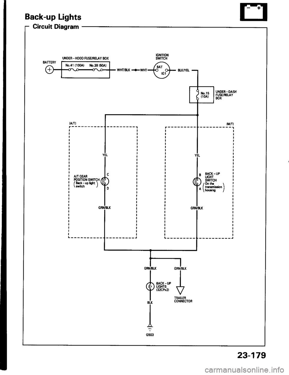
Back-up Lights
Circuit Diagram
wHT/Bt( +WHT
A/T GEARPosrnotr swrTcHf 8ek - up lioht 'l
--------_JL---------
UI{DER_ IIOOO FUSEiBEIAY BOX
23-179
Page 1287 of 1413
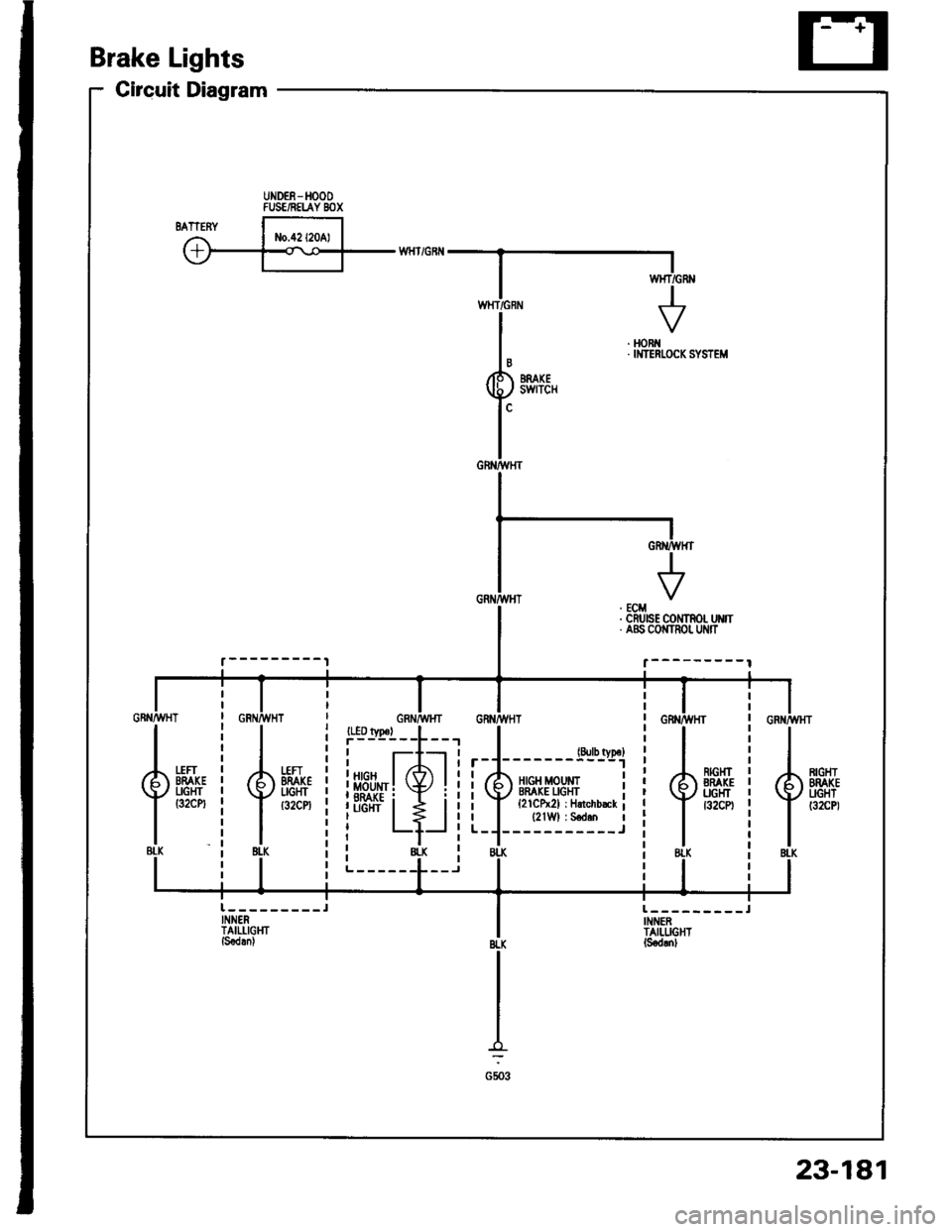
Circuit Diagram
Brake Lights
UNDEE-HOOOFUSE/NELAY BOX
. HORi{. IMTERI.OCK SYSTEM
{.BLK
*H-i
{.{u8tK
23-181