fuse chart HONDA INTEGRA 1994 4.G Workshop Manual
[x] Cancel search | Manufacturer: HONDA, Model Year: 1994, Model line: INTEGRA, Model: HONDA INTEGRA 1994 4.GPages: 1413, PDF Size: 37.94 MB
Page 440 of 1413
![HONDA INTEGRA 1994 4.G Workshop Manual Troubleshooting Procedures
when the TcM senses an abnormality in the input or output systems. the E]indicator light in the gaugo assembly willblink.
when the service check Connector {located under the HONDA INTEGRA 1994 4.G Workshop Manual Troubleshooting Procedures
when the TcM senses an abnormality in the input or output systems. the E]indicator light in the gaugo assembly willblink.
when the service check Connector {located under the](/img/13/6067/w960_6067-439.png)
Troubleshooting Procedures
when the TcM senses an abnormality in the input or output systems. the E]indicator light in the gaugo assembly willblink.
when the service check Connector {located under the dash on the passenger side} is connected with the specaat toolas shown, the E] indicator light will blink the Diagnostic Trouble iode {DTCI when the ignition switch is turned on.
When the lDil indicator light has been reported on, connect the service check connector with the special tool.Then turn on the ignition switch and observe the @ indicator light.
GAUGE ASSEMSLY
)'t
DAI'A LI]TKcor{r{EcToR (3P)NOTE:Do not atlachjumpe. wire.
Sc. DTCI
So. DTC2
S.. DTC14
scs sHoRT CO[{]{ECTORoTPAZ-OOl0too
codes 1 through I are indicated by individual short blinks, codes 1o through 1 5 are indicated by a series of tong andshon blinks. one long blink equals l0 short blinks. Add the long and short blinks together to dete;mins the cod€. Aft6rdetermining the code, refer to the erectricar system symptom-to-component chart on pages 14-5o and 51.
ahon
f"l
some PGM-FI problems will also make the @ indicator light come on. After repairing the pGM-Fr system, disconnectthe BACK UP tuse (7.5 Al in the under-hood fuse/relay box tor more than 1o seconds to reset the TcM memorv.
NOTE:
a PGM-FI svstem
The PGM-FI system on this model is a sequential multipon fuel iniection svstem.' Disconnecting the BACK UP tuse also cancels the radio anti-theft code, preset stations and the clock setting. G6tthe customer's code numbe. and make note of the radio presets befote temoving the fuse so you can reset them.
14-48
Page 441 of 1413

CAUTIOI{:
a All SRS eloctdcal wiring harna$os are covcred whh
yollow lnaulation.
a Sofora disconnecting any pan ot tho SRS wirc har'
n6ss, connoct the short connoctots (s€6 pago 23-701.
a Roplacs tho entiro aff.ct d SRS ham6t. rssombly it
ii has an opon circuil or damagcd wlrlng.
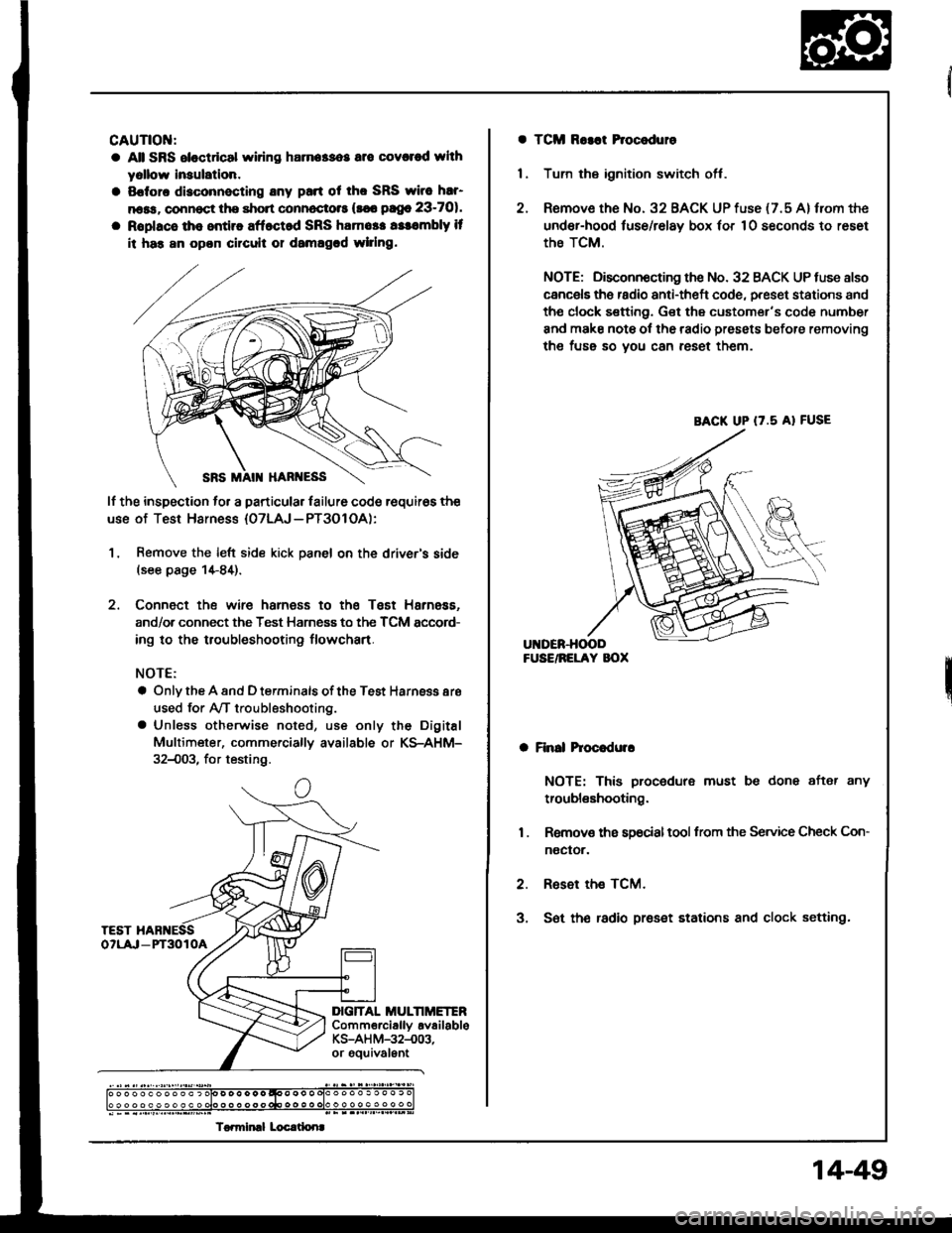
lf the inspection to. a particular lailure code requir6s the
use of Test Harness {07LAJ - PT3O1 OA):
1, Remove the left side kick panel on the driver's side(see page 1+84).
2. Connect the wire harness to the Tsst Harness.
and/or connect the Test Harness to the TCM sccord-
ing to the troubleshooting flowchart.
NOTE:
a Only the A and D terminals of the Test Harnsss aro
used for Ay'T troubleshooting.
a Unless otherwise noted, use only the Digital
Multimeter, commerciallv available or KS-AHM-
32{)03, for testing.
c
DIG]TAL MULTIMETERComm€rciallv availableKS-AH M-32-.003,or gouivalEnt
) o o o o o o o o o o ) olo D o o o o o qoo o o o olo o o o o . o o o . c
To.miml Locrtlonr
a TCM Ro3at Procoduro
1 . Tum the ignition switch off.
2. Remove the No. 32 BACK UP fuse {7.5 A} from the
under-hood luse/relay box 'or 10 seconds to reset
the TCM.
NOTE; Disconnocting the No. 32 BACK UP tuse also
cancels ths radio anti-theft code, preset stations and
tho clock sefting. Get the customer's code number
and make note ol the radio presets before removing
the fuss so you can reset them.
a Finll hoc.dulr
NOTE: This procedure must be done after any
troubleshooting.
1 . Removs ths s9ocialtool from the Service Check Con-
noctor.
2. Reset the TCM.
3, S6t th€ radio preset stations and clock setting.
BACK UP (7.5 A} FUSE
14-49
Page 1075 of 1413

Troubleshooting
Reference Ghart
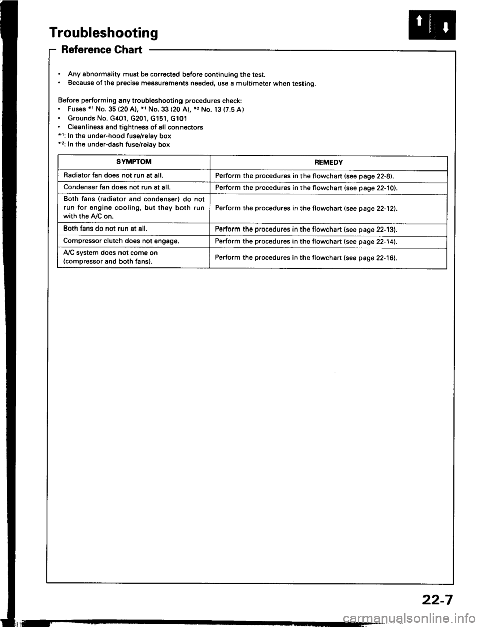
. Any abnormality must be correctsd before continuing the test.. Because of the precise measurgments needed, use a multimeter when testing.
Before performing any troubleshooting procedures check:. Fus€s .r No. 35120 A), *1 No. 33 (20 A), ), No. 13(7.5A). Grounds No. G401, G201, G'151, G101. Cleanliness and tightness of all connectors*1: In the under-hood fuse/relay box*2: In the under-dash fuse/relay box
SYMPTOMREMEDY
Radiator fan does not run 8t all.Perform the procedures in the flowchan (see page 22-8).
Condenser fan does not run at all.Perform the procedures in the flowchart (see page 22-10).
Both fans (radiator and condenser) do not
run for engine cooling, but they both run
with the Ay'C on.
Perform the procedures in the flowchan (see page 22-12).
Eoth fans do not run at all.Perform the procedures in the flowchart (see page 22-13).
Compressor clutch does not engage.Perform the procedures in the flowchart (see page 22-14).
Ay'C system does not come on
{compressor and both fans}.Perform the procedures in the flowchart (see page 22-16).
22-7
Page 1172 of 1413

Battery
a Battory tluid (6lectrolyt€l contains sulturic acid. lt may cauaa aevere burns iI it gots on your skin or in youl oyos.
Woar protoctivo clothing and I fac€ shield,- ll aloctrolyt6 gots on youl skin or clothos, rimo it off with wator immediately,- lf eloclrolyto g6ts in your oyos, tlush it out by splashing wat6r in youl eyes for at least 15 minutes; call a physiclan
immediately,
a A battery gives off hydrogon gas, lf ignit6d. tha hydrogsn will orploda and could crack tho baflory cas6 and splattor
acid on you. Koep spa*s. flames, and cigarottos away from the baftery.
a Overcharging will raiso ths tempelature ot th€ electrolyte. This may force electrolyte to splay out of the battery venta.
Follow lhe chargor manutacturer's instluctions and chargo tho battory at a prop61 rate.
NOTE: The original radio has a coded theft protection circuit. lt service to the car requires any of the lollowing, be sure
to get the customer's code number before- disconnecting the battery.- removing No. 32 (7.5 Al fuse from the under-hood fuse/relay box- removing the radio,
After service, reconnect power to the radio and turn it on. When the word "CODE" is displayed, enter the customer's
s-digir code to restore radio operation,
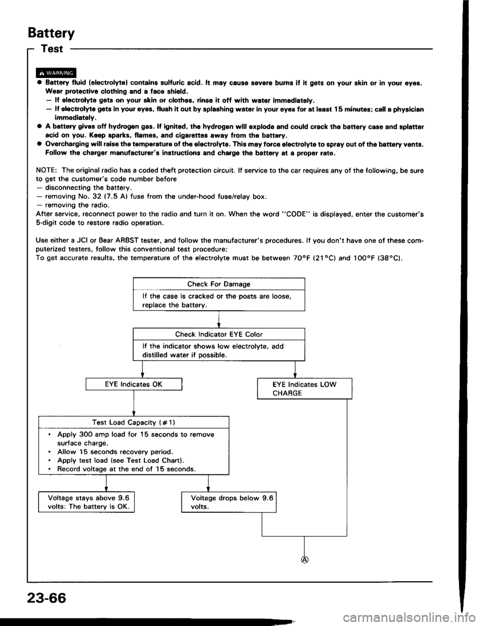
Use either a JCI or Bear ARBST tester, and follow the manufacturer's procedures. It you don'r have one of these com-puterized testers, follow this conventional test procedure:
To get accurate results, the temperature ot the electrolyte must be between TOoF l21ool and IOOoF {38oCl.
lf the case is cracked or the posts are loose,
replace the battery.
lf the indicator shows low electrolvte, add
distilled water it oossible.
Test Load Cspacity (# 1)
. Apply 3OO amp losd fo. 15 seconds to remove
surJace charge.. Allow 15 seconds recovery period.. Apply test load (see Test Load Chartl.. Record voltage at the end of 15 seconds.
Voltage stays above 9.6
volts: The batterv is OK.
23-66
Page 1397 of 1413

Supplemental Restraint System (SRSI
Troubleshooting {cont'dl
Modc H: Blown SRS No. 25 fur., ol opcn in the wire
NOTE: The original radio has a coded theft protection
circuit. Be sure to get the customer's code number
betore disconnecting the battery cables.
1. Ch€ck the SRS No. 25 (10 A) fuse in the under-dash
fuse/relay box. lf it's OK, go on to step 2.
lf it's blown, replace it with a now 10 A fuse, then
turn the ignition switch ON (ll):
. lf the fuse doesn't blow, 90 on to step 2.
. lf the fuse blows. troublsshoot as necessary to
find th6 short.
2. Disconnect the battery negative cable and then the
positive cable. Then connect the short connector(sl
(RED) to the airbag(s) (see page 23-272).
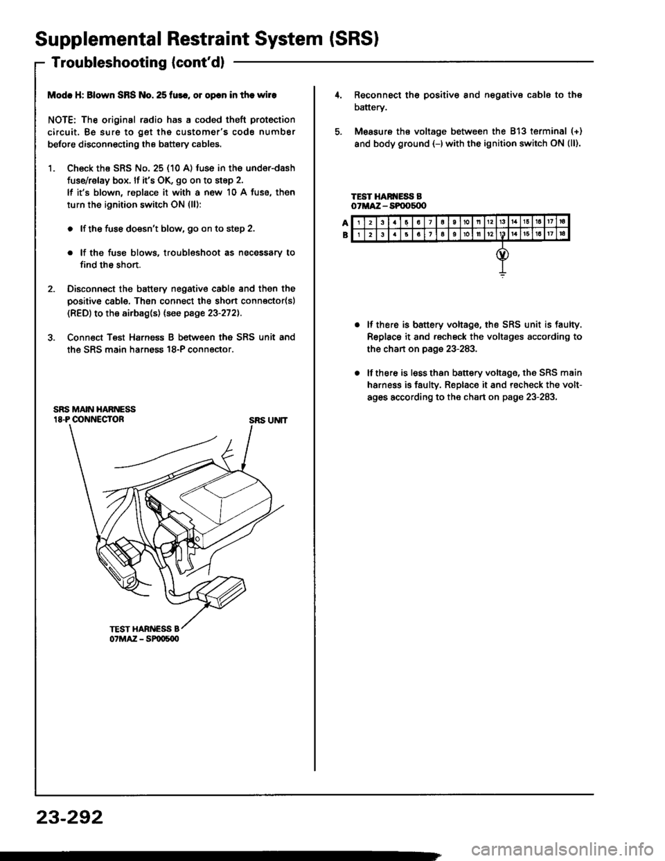
3. Conn€ct Teat Harnsss B between the SRS unit and
the SRS main harness 18-P connector.
SRS UNIT
23-292
23a7a10nl3161a17ra
26161oll12161a17|a
Reconnect th6 positiv€ 8nd negative cable to the
battery.
Measure ths voltage between the 813 terminal (+)
and body ground {-)with the ignition switch ON (ll).
TEST HAN ESS BoTMA:Z - SPOOs{X'
lf there is battery voltage, the SRS unit is faulty.
Replace it and rscheck the voltages according to
the chan on page 23-283.
lf there is lsss than b8ttery voltage, the SRS main
harness is faulty. Replace it and recheck the volt-
ag6s according to the chart on page 23-283.