knuckle HONDA INTEGRA 1994 4.G Workshop Manual
[x] Cancel search | Manufacturer: HONDA, Model Year: 1994, Model line: INTEGRA, Model: HONDA INTEGRA 1994 4.GPages: 1413, PDF Size: 37.94 MB
Page 556 of 1413
Transmission
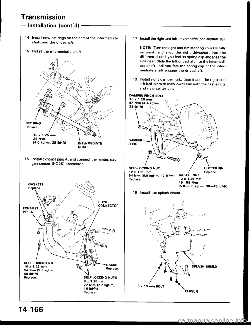
Installation {cont'd)
14.
15.
Install new set rings on the end of the intermediate
shaft and the driveshaft.
Install the intermediate shaft.
SET RINGBeplace.
16.
10 x 139 N.m14.O kgf.m, 29 lbf.ftl
Install exhaust pipe A. and connect the heated oxv-gen sensor {HO2S) connector.
SELF-LOCKING NUT10 x 1.25 mm54 N.m (5.5 kgl.m,40 rbt.trlReplace.
GASKETReplace.
SELF.LOCKING NUTSI x 1.25 mm22 N.m 12.2 kgl'n,16 lbt.trlRepl6ce.
SHAFT
14-166
DAMPER PINCH BOLT10 x 1.25 mm43 N.m 14.4 kgf.m,32 tbr.ftl
1 7. Install the right and left drivershafts (see section l6l.
NOTE: Turn the right and left steering knuckle fullyoutward, and slide the right driveshaft into the
differential until you feel its spring clip engages theside geaf. Slide the left driveshaft into the intermedi-
ate shaft until you teel the spring clip of the inter-mediate shaft engage the driveshaft.
18. Install right damper fork, then install the right andlett balljoints to each lower arm with the castle nuts
and new cotter Dins.
\
COTTERReplace.CASTLE NUT12 x 1.25 mm49-59 N.m{5.O-6.0 ksf.m, 36-43
SELF.LOCKING NUT12 x 1 .25 mm64 N.m (6.5 kgl.h, 47 lbt.ftlReplace.
rbt'ft1
19. Install the splash shield.
6 x 10 mm BOLT
cltPs, 5
Page 597 of 1413
KNUCKLE
DRIVESHAFT
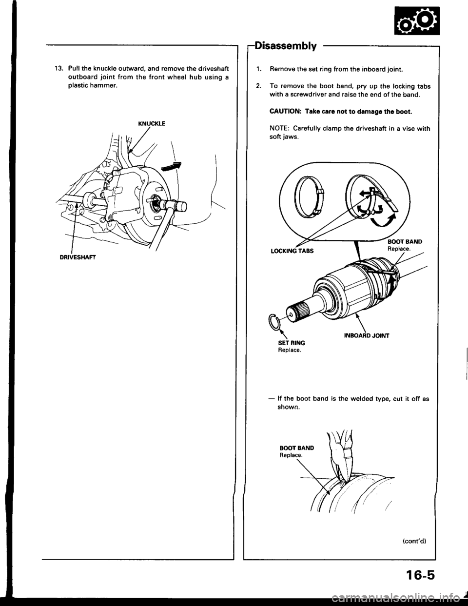
13. Pull the knuckle outward, and remove the driveshaft
outboard joint from the front wheel hub using I
Dlastic hammer.
Remove the set ring from the inboard joint.
To remove the boot band, pry up the locking tabs
with a screwdriver and raise the end of the band,
CAUTION: Taks caro not to damagc thc boot.
NOTE: Carefully clamp the driveshaft in a vise with
soft iaws.
SET RINGReplace.
- lf the boot band is the welded type, cut it off as
snown,
1.
16-5
Page 602 of 1413
Driveshafts
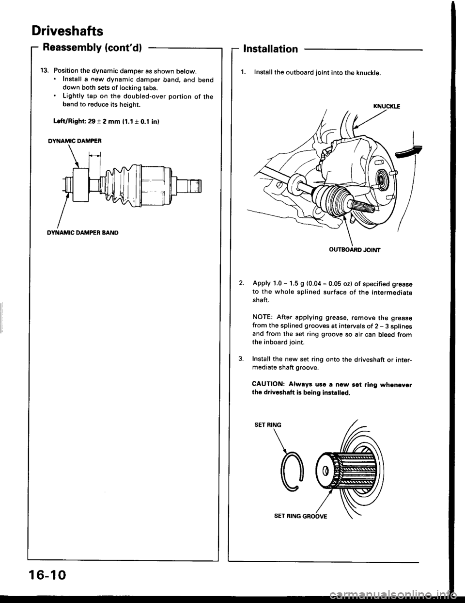
Position the dynamic damper as shown below.. Install a new dynamic damper band. and benddown both sets of locking tabs.
Lightly tap on the doubl€d-over ponion of theband to reduce its height,
Loft/Right 29 r 2 mm (1.1 r 0.1 inl
DYNAMIC DAMPER
t5.
Reassembly (cont'dl
DYNAMIC DAMPER BANO
Installation
1. Install the outboard joint into the knuckle.
KNUCIGE
Apply 1.0 - 1.5 s (0.04 - 0.05 oz) of specified groase
to the whole splined surtace of the intermediatsshaft.
NOTE: After applying grease, remove the grsase
f.om the splined grooves at intervals of 2 - 3 sDlinesand from the set ring groove so air can bleed fromthe inboard joint.
Install the new set ring onto the driveshaft or inter-mediate shaft groove.
CAUTION: Always uso a now sot ring whcncycrtho driveshaft is boing in3tallod.
RING
b
OUTBOARD JOINT
16-10
SET RING GROOVE
Page 603 of 1413
5.
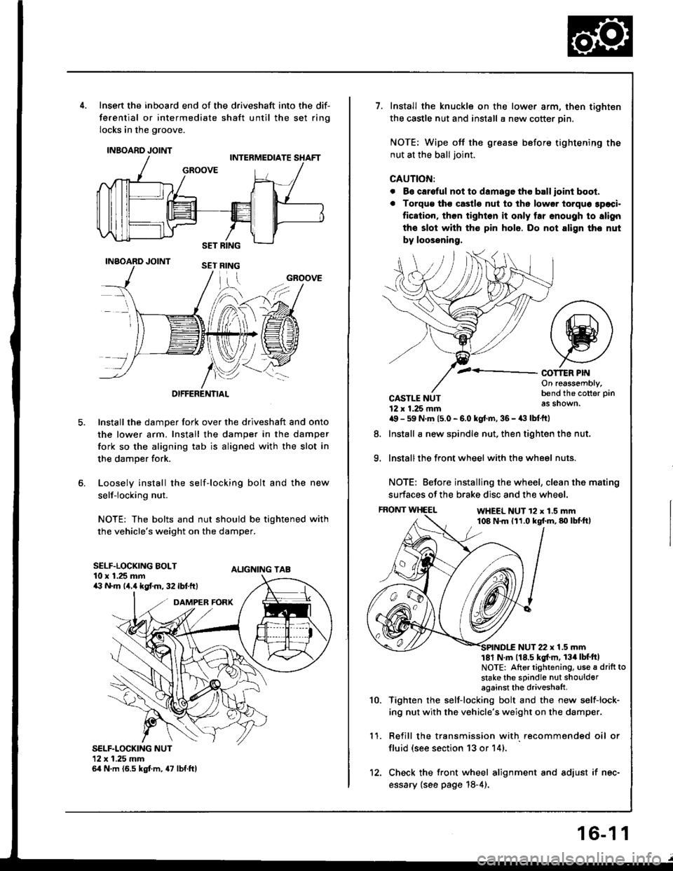
Insert the inboard end of the driveshaft into the dif-
ferential or intermediate shaft until the set ring
locks in the groove.
INBOARD JOINT
INAOARD JOINT
OIFFERENTIAL
Install the damper fork over the driveshaft and onto
the lower arm. Install the damper in the damper
fork so the aligning tab is aligned with the slot in
the damper fork.
Loosely install the self-locking bolt and the new
self-locking nut.
NOTE: The bolts and nut should be tightened with
the vehicle's weight on the damper.
ALIGNING TAB
SELF.LOCKING NUT12x 1.25 mm64 N.m (6.5 kgt m, 47 lbf.ftl
GROOVE
SELF.LOCKING BOLT10 x 1.25 mma:' N.m lir,4 kgt m, 32 lbf.ftt
1.Install the knuckle on the lower arm, then tighten
the castle nut and install a new cotter pin.
NOTE: Wipe off the grease before tightening the
nut at the ball joint.
CAUTION:
. B€ careful not to damago tho ball ioint boot.
. Torqu€ tho castle nut to ths lower torquo 3paci.
fication, then tighlon it only tar snough to slign
the slot with th€ pin hole. Do not align tho nut
by loossning,
COT1ER PIf{On reassembly,bend the cotter pin
as shown.
9.
CASTLE NUT12 x 1.25 rnma9 - 59 N.m 15.0 - 6.0 kgt.m, 36 - a:t lbtftl
Install a new spindle nut, then tighten the nut,
Install the front wheel with the wheel nuts.
NOTE: Before installing the wheel, clean the mating
surfaces of the brake disc and the wheel.
FRONT WHEELWHEEL NUT 12 x 1.5 mm108 N.m (11.0 kgf.m,80lbtft,
8.
1 '�I.
10.
NUT 22 x 1.5 mm181 N m 118.5 kgl'm, 134lbt'ftlNOTE: Altor tightening, use a drift to
stake the sPindle nut shoulderagainst the driveshaft
Tighten rhe self-locking bolt and the new self-lock-
ing nut with the vehicle's weight on the damper.
Refill the transmission with recommended oil or
fluid (see section 13 or 14).
Check the front wheel alignment and adjust if nec-
essary {see page 18-4).
12.
16-1 1
Page 652 of 1413
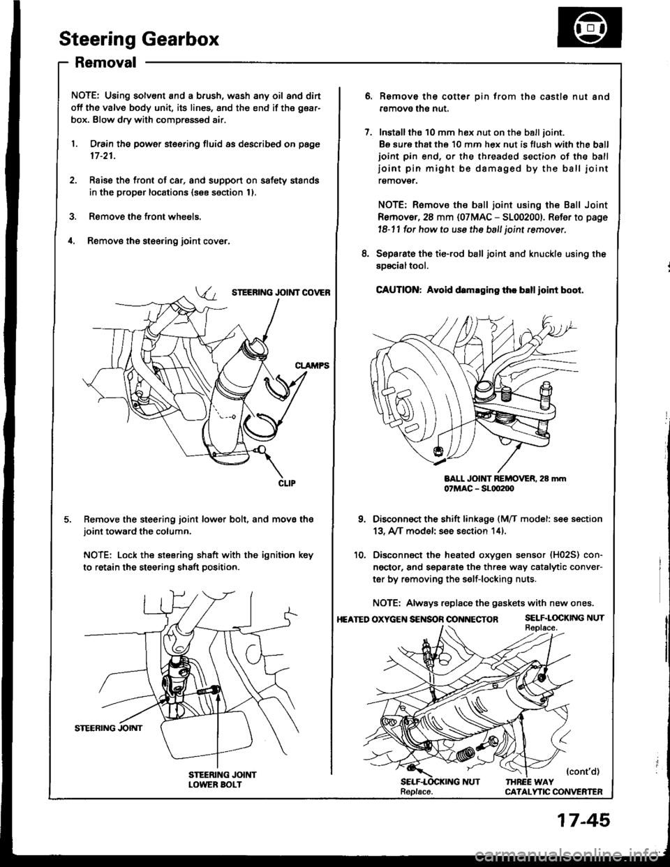
Steering Gearbox
Removal
NOTE: Using solvent and a brush, wash any oil and dirt
off the valve body unit, its lines, and the end if the gear-
box. Blow dry with compressed air.
1. Drain the power steering fluid as described on page
17 -21.
2. Rsise the front of car, and support on safety stands
in the propsr locations (see section 1).
3. Remove the front wheels.
il. Removs the st€ering joint cove.,
SIEERING JOIi{T COVEB
Remove the steering joint lower bolt, and move thejoint toward the column.
NOTE: Lock the steering shaft with the ignition key
to retain the steering shaft position.
Remove the cotter pin trom the castle nut and
removo the nut.
Installthe 10 mm hex nut on the balljoint.
Be sure that ths 10 mm hex nut is flush with the ball
ioint pin end, or the threaded section of the ball
ioint pin might be damaged by the ball iointremover.
NOTE: Remove the ball joint using the Ball Joint
Remover, 28 mm {07MAC - 5100200}. Refer to page
l8-11 fot how to use the ball joint rcmover,
Separat€ the tie-rod ball joint and knuckle using the
soscialtool.
CAUTION: Avold d.maging th. blllloint boot.
BALL JOlt{T REMOVER. 28 mm07MAC - SLqt2|X)
Disconnect the shift linkage {MfI model: see section
13, A/[ model see section 14).
Disconnect the heated oxygen sensor (H02S) con-
ngctor, and separate the three way catalytic conver-
ter by removing the s€lf-locking nuts.
NOTE: Always replace the gaskets with new ones.
OXycEt{S€NSOnOONNECTOR SELF.LOCKINGNUT
{cont'd)IHREE WAYCA?ALYTIC CONVERTEN
8.
10.
HEATED
Replacs.
17-45
Page 672 of 1413
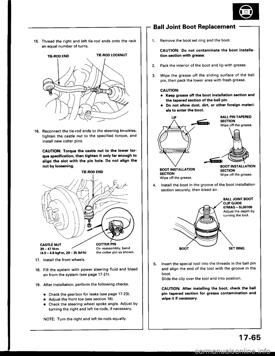
15.Thread the right and lefi tie-rod ends onto the rack
an eoual number of turns.
TIE-ROO ENDTIE.ROD LOCKNUT
R€connect the tie-rod ends to the steering knuckles,
tighten the castle nut to the specified torque, and
install new cotter pins.
CAUTION: Iorquo tho castle nut to tho lower tor-
que lpocification, thsn tighton it only far cnough to
align thc slot with tho pin hole. Do not align tho
nut by loosoning.
CASILE NUT39 - 47 N.m14.0 - a.8 kgf.m. 29 - 35 lbf ftl
17. lnstallthe front wheels.
18. Fill the system with pgwer steering fluid and bleed
air from the system (see page 17-21).
19. After installation. perform the following checks.
. Check the gearbox Jor leaks (see page 17-231
. Adjust the front toe (see section 18).
o Check the steering wheel spoke angle. Adjust by
turning the right and left tie-rods, if necessary.
Ball Joint Boot Replacement
Remove the boot set ring and the boot.
CAUTION: Do not contaminate ihe boot in3talls-
tion section with gr€aso.
Pack the interior of the boot and lip with grease.
Wipe the grease off the sliding surface of the ball
pin, then pack the lower area with fresh grease.
CAUTION:
. Ke€p g;eass off the boot in3tallation section and
tho laperad section of the ball pin.
. Do not altow dust, di.t, or other toreign mat6ti-
als to enter tho boot,
LIPBALL PIN TAPEREDSECTIONWipe off the grease.
BOOT INSTALLATIONSECTIONwiDe off the grease.
BOOT INSTALLATIONSECTIONWipe off the grease.
COTTER PINOn reassembly, bendthe cotter pin as shown.
Install the boot in the groove ot the boot installation
section securely, then bleed air.
SALL JOINT BOOTCLIP GUIDE07MAG - SL(x)l00Adiust the depth byturning the tool.
SET RING
Insert the special tool into the threads in the ball pin
and align the end of the tool with the groove in the
boot.
Slide the clip over the tool and into position
CAUTION: After installing the boot, check th. b.ll
pin taperod section tor grease contamiration and
wipe it if nocossary.
NE.ROD END
Turn the right and left tie-rods equally.
17-65