washer fluid HONDA INTEGRA 1994 4.G Workshop Manual
[x] Cancel search | Manufacturer: HONDA, Model Year: 1994, Model line: INTEGRA, Model: HONDA INTEGRA 1994 4.GPages: 1413, PDF Size: 37.94 MB
Page 52 of 1413
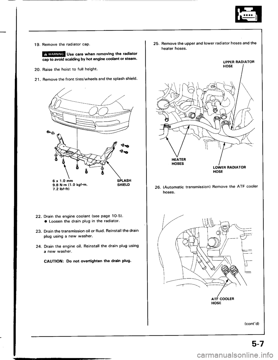
19. Remove the radiator cap.
@@ u"" care whan removing the ladiatol
cap to avoid scalding by hot engine coolant ol ateam.
20. Raise the hoist to full height.
21. Remove the front tires/wheels and the splash shield.
Drain the engine coolant (see page 1O-5).
a Loosen the drain plug in the radaator.
Drain the transmission oil or fluid. Reinstall the dtain
plug using a new washer.
Drain the engine oil. Reinstall the drain plug using
a new wasner.
CAUTION: Do not overtighten tho drain plug.
22.
24.
6 x 1.O mm9.8 N.m (1.0 kgf'm'7.2 tbf.ft)26.
25. Remove the upper and lower radiator hoses and the
heater hoses.
LOWER RADIATORHOSE
(Automatic transmission) Remove the ATF cooler
hoses.
{cont'd)
UPPER RADIATOR
HOSE
5-7
Page 485 of 1413
Fluid Level
Checking/Changing
Checking
NOTE: Check the fluid level with the engine at normal
operating temperature (the cooling lan comes on).
1. Park the car on level ground. Shut otf the engine.
2. Remove the dipstick (yellow loop) from the trans-
mission, and wipe it with a clean cloth.
3. Insert the dipstick into the transmission.
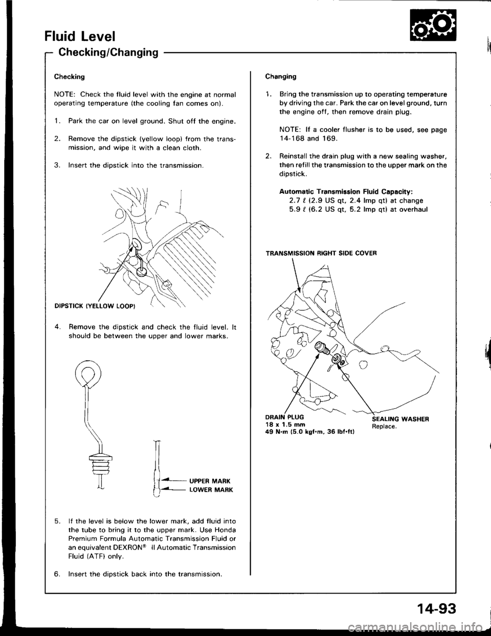
DIPSTICK (YELLOW LOOPI
4. Remove the dipstick and check the fluid level.
should be between the uoDer and lower marks.
P
il
\---
T
lf the level is below the lower mark, add fluid into
the tube to bring it to the upper mark. Use Honda
Premium Formula Automatic Transmission Fluid or
anequivalentDEXRON@ llAutomaticTransmission
Fluid (ATF) only.
lnse.t the diDstick back into the transmission.
IT
{J. UPPER MARK
t)-i- LowER MARK
5.
6.
Changing
1. Bring the transmission up to operating temperature
by driving the car. Park the car on level ground, turn
the engine oft, then remove drain plug.
NOTE: lf a cooler flusher is to be used, see page
14-168 and 169.
2. Reinstail the drain plug with a new sealing washer,
then refillthe transmission to the upper mark on the
dipstick.
Automatic Transmission Fluid Capacity:
2.1 | l2.S US qt, 2.4 lmp qt) at change
5.9 ? (6.2 US qt, 5.2 lmp qt) at overhaul
18 x 1.5 mm49 N.m (5.0 kgl.m, 36 lbl.ft)
TRANSMISSION RIGHT SIDE COVER
14-93
Page 486 of 1413
Pressure Testing
a While testing, be caretul of the rotating flont wheels.a Make aura litts, jacks, and sat€ty stands alo placedplop6rly {see section 1}.
CAUTION: Betore t€sting, be sure the transmission fluidis tilled to rh6 ploper l€vet.
1. Raise the car (see section i),
2. Warm up the engine {the cooling fan comes onl, thenstop the engine and connect a tachometer.
3. Connect the oil pressure gauge to each inspectionholels).
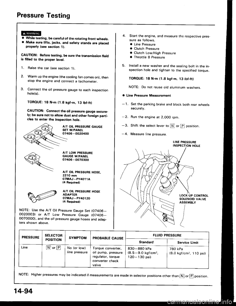
TOROUE: 18 N.m (1.8 kgf.m, 13 tbf.fr)
CAUTION: Connect ths oil prsssure gauge s€cur€_ly; be sule not to allow dust and other foleign pani_cl6s to 6nt€1 th€ inspection holo.
A/T OIL PRESSURE GAUGESET WPANEL07406-002oi+oo
A/T LOW PRESSUREGAUGE W/PANEL07/rO6-0O70300
A/T OIL PRESSURE HOSE,22'10 mmOTMAJ_PY4OI TA{4 Roquirod)
A/T OIL PRESSUBE HOSEADAPTEROTMAJ - PY/+O12014 Roqui.odl
NOTE: Use the A/T Oil Pressure Gauge Set (07406_O02OOO3) or A/T Low Pressure Gauge (07406-OOTO0OO). and the oil pressure gauge hoses and adap_ters shown above.
14-94
4. Start the engine, and measure the respective pres-
sure as follows.
a Line Pressure
a Clutch Pfessure
a Clutch Low/High Pressure
a Throttle B Pressure
5. Install a new washer and the sealing bolt in the in-spection hole and tighten to the specified torque.
TOROUE: 18 N'm {1.8 kgf.m, 13 tbf.ft)
NOTE: Do not reuse old aluminum washers.
a Line Pressure M€asurement
- 1 . Set the parking brake and block both rear wheelssecurely.
-2. Run the engine at 2,OOO rpm
-3. Shift the selecr lever to S or @ position.
-4. Measure line pressure.
LINE PRESSUREINSPECTION HOLE
NoTE: Higher pressures may be indicated it measurements are made in selector positions other than @ or @ position.
PRESSURESELECTOR
POStTTONSYMPTOMPROBABLE CAUSEFLUID PRESSURE
StandardService Limit
LineNo'ENo (or low)
lrne pressureTorque converter,
orl pump, pressure
regulator, to.que
convener check
valve
83O-88O kPa(8.5-9.O kgf/cm,,
120- I 30 psi)
78O kPa
{8.0 kgl/cm,, 1lO psi}
Page 1126 of 1413
Connector ldentification and Wire Harness Routing
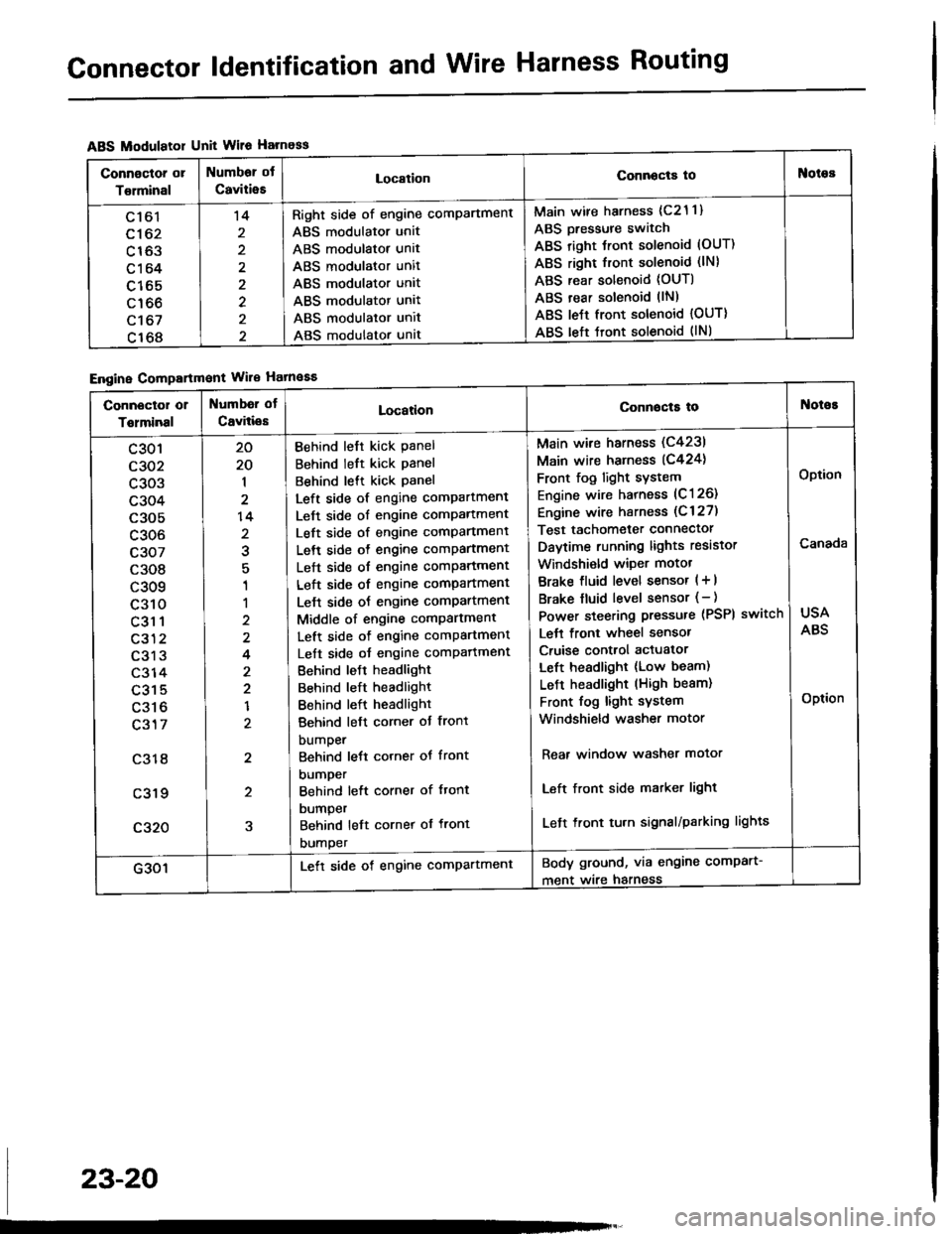
ABS Modulatol Unit Wile Harness
Engine Compartmont Wile Hatnaaa
Connoctor or
Torminal
Numbor ot
CaviiieELocationConnocta tooies
Ltol
c162
c163
c164
c165
c166
c't 67
c168
't4
2
2
Right side of engine comPartment
ABS modulator unit
ABS modulator unit
ABS modulator unit
ABS modulator unit
ABS modulator unit
ABS modulator unit
ABS modulator unat
Main wire harness (c21 1)
ABS Dressure switch
ABS right Jront solenoid (OUT)
ABS right front solenoid (lN)
ABS rear solenoid (OUT)
ABS rear solenoid llN)
ABS le{t front solenoid {OUT)
ABS left tront solenoid (lNl
Connector or
Tolminal
Numbd of
CaviliesLocationConnocta tot{oioE
c301
c302
c303
c304
c305
c306
c307
c308
c309
c310
c31 1
c312
c313
c314
c315
c316
c317
c318
c319
c320
20
20
1
2
14
2
1
1
2
4
2
2
1
2
2
5
Behind left kick Panel
Behind left kick panel
Behind lett kick Panel
Left side of engine compartment
Left side of engine comPartment
Left side of engine comPartment
Left side o{ engine comPartment
Left side of engine comPartment
Left side of engine compartment
Lelt side oJ engine comPartment
Middle of engine comPartment
Left side of engine comPartment
Left side oJ engine comPafiment
Behind leJt headlight
Behind left headlight
Behind left headlight
Behind left corner ot front
bumper
Behind lett corner ot front
DUmper
Behind left corner of ftont
DUmper
Behind left cornet of front
DUmper
Main wire harness (C4231
Main wire harness (C424)
Front fog light sYstem
Engine wire harness (C126)
Engine wire harness (C 127)
Test tachometer connector
Daytime running lights resistor
Windshi€ld wiper motot
Brake fluid level sensor ( + |
Brake fluid level sensor (- )
Power steering pressure (PSPI
Lett front wheel sensor
Cruise control actuator
Left headlight (Low beam)
LeJ-t headlight (High beam)
Front fog light system
Windshield washer motor
switch
Rear window washer motor
Left front side matker light
Left front tu.n signal/parking lights
USA
ABS
Option
Canada
Option
G301Lett side of engine comPartmentBody ground, via engine comPart-
ment wire harness
23-20
Page 1362 of 1413
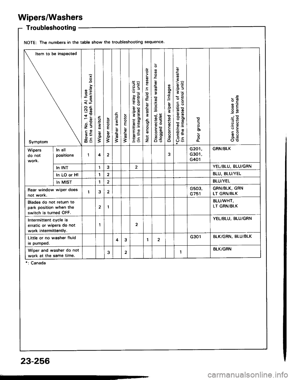
Wipers/Washers
Troubleshooting
NOTE: The numbers in the table show the troubleshooting sequence
Item to be insDected
Symptom
i
oo-;i
a.P
:6r!
z)
it
3
o
=
o
E
;
E;
3
E
ID
3
95'6;
>;
eb
rD!otD
;E
cqt
EP
0,(t
i
z
o
=Y.
.9! O
o
t
oo
o
6
i=
.45i5
bE
€3
dOot
Eroc
o
o
o-
o.
:!
-c
oo
Wipers
do not
ln all
positionsI422G301,
G401
GRN/BLK
ln INTI3YEL/BLU,8LU/GRN
In LO or Hl12BLU, BLU/YEL
ln MIST1BLU/YEL
Rear window wiper does
not work.1aG503,
G751
GRN/BLK, GRN
LT GRN/BLK
Blades do not return to
park position when the
switch is turned OFF.
I
BLU/wHT,
LT GRN/BLK
Intermittent cycle is
erratic or wipers do not
work intermiftently.
12
YEL/BLU. BLU/GRN
Little or no washer fluid
is pumped.4?12G301BLK/GRN, BLU/BLK
WiDer snd washer do not
work at the same time.1BLK/GRN
23-256
Page 1369 of 1413
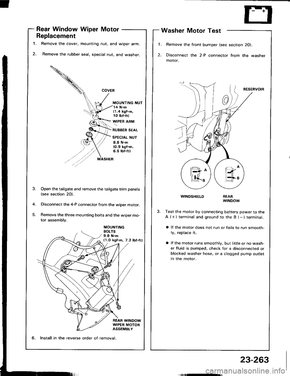
l.
2.
1.
Rear Window Wiper Motor
Replacement
Remove the cover, mounting nut, and wiper arm.
Remove the rubber seal, special nut, and washer.
MOUNTING NUT
Washer Motor Test
Remove the front bumper (see section 20).
Disconnect the 2-P connector lrom the washer
motor.
RESERVOIR
WINDSHIELD
14 N.m11.4 kgf.m,10 tbt.trl
WIPER ARM
RUBBER SEAL
SPECIAL NUT
8.8 N.m{0.9 kgt'n,6.5 rbt.fr)
MOUNTINGBOLTS9.8 N.m(1.O kgf.m, 7.2 lbf.ttl
-4
)
Open the tailgate and remove the tailgate trim panels(see section 20).
Disconnect the 4-P connector from the wiper motor.
Remove the three mounting bolts and the wiper mo-
tor assembly.
REARwrNDow
Test the motor by connecting battery power to the
A ( + ) terminal and ground to the B (- ) terminal.
a ll the motor does not run or fails to run smooth-
ly, replace it.
a lf the motor runs smoothly, but little or no wash-
er fluid is pumped. check for a disconnected orblocked washer hose, or a clogged pump outlet
in the motor.
6, Install in the reverse order o{ removal.
23-263