Distributor HONDA INTEGRA 1998 4.G User Guide
[x] Cancel search | Manufacturer: HONDA, Model Year: 1998, Model line: INTEGRA, Model: HONDA INTEGRA 1998 4.GPages: 1681, PDF Size: 54.22 MB
Page 1075 of 1681
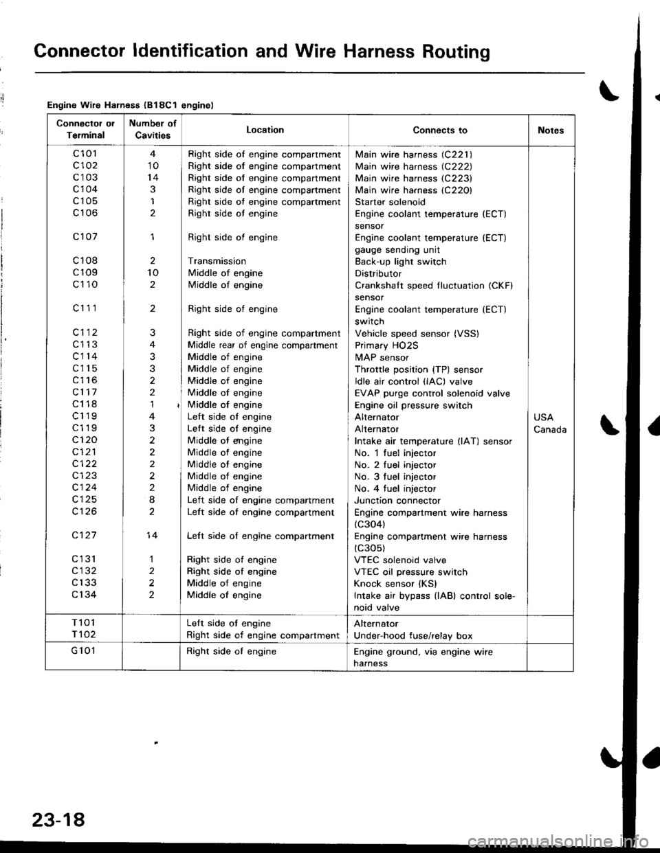
Connector ldentification and Wire Harness Routing
Engine Wire Harness (B18Cl enginel
Connectol ol
Terminal
Number of
CavitiesLocationConnects toNotes
c 101
c102
c103
c104
c105
c106
c101
c108
cr09
c110
c'r 11
cl12
c1't3
c114
c115
c116
cl17
c118
c119
c119
c120
cI2'l
cl24
c126
c127
cl31
c132
c133
c134
10
14
3
1
2
1
2
10
2
'I
3
2
2
2
I
1
2
2
?
3
2
14
Right side of engine compartment
Right side of engine compartment
Right side of engine compartment
Right side ol engine compartment
Right side of engine compartment
Righr side oI engine
Right side of engine
Transmission
Middle of engine
Middle of engine
Right side of engine
Right side of engine compartment
Middle rear of engine compartment
Middle of engine
Middle of engine
Middle of engine
Middle of engine
i/iddle of engine
Left side ot engine
Lelt side ot engine
Middle ot engine
Middle of engine
Middle of engine
Middle of engine
Middle of engine
Left side of engine companment
Left side of engine compartment
Lelt side of engine compartment
Right side of engine
Right side of engine
Middle of engine
Middle of engine
lvlain wire harness (C221 )
Main wire harness {C222)
Main wire harness (C223)
Main wire harness (C220)
Starter solenoid
Engine coolant temperature (ECT)
sensor
Engine coolant temperature (ECT)
gauge sending unit
Back-up light switch
Distributor
Crankshalt speed fluctuation (CKFI
sensor
Engine coolant temperature {ECT)
switch
Vehicle speed sensor (VSS)
Primary HO2S
MAP sensor
Throttle position {TP) sensor
ldle air control (lAC) valve
EVAP purge control solenoid valve
Engine oil pressure switch
Alternator
Alternator
Intake air temperature llAT) sensor
No. 1 fuel injector
No. 2 fuel injector
No. 3 tuel injector
No. 4 tuel injector
Junctron connector
Engine compartment wire harness(c304)
Engine companment wire harness(c30s)
VTEC solenoid valve
VTEC oil pressure switch
Knock sensor (KS)
Intake air bypass {lAB) control sole-
noid valve
USA
Canada
T101
r 102
Left side ot engine
Right side of engine compartment
Alternator
Under-hood fuse/relay box
G 101Right side of engineEngine ground, via engine wire
naaness
23-18
Page 1145 of 1681
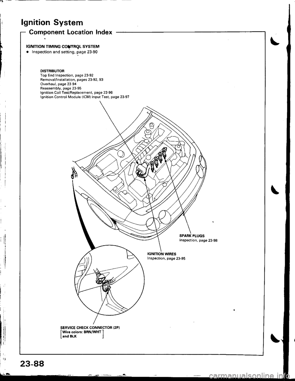
lgnition System
23-88
Component Location lndex
rGNlTroN TTMTNG COJTRqL SYSTEM
. lnspection and sefting, page 23-90
DISTRIBUTORTop End lnspeclion, page 23-92Removal/lnstallation, pages 23-92, 93Overhaul, page 23 94Reassembly, page 23-95lgnition Coil TesvReplacement, page 23 96lgnition Control Module (lCM) lnput Test, page 23-97
PLUGSInspection, pago 23-98
IGN'TION WIRESInspection, page 23-95
SERVICE CHECK CONNECTOR I2PIIWi]6 coloEi BRN/WHT I
land BLK j
Page 1151 of 1681
b-.
23-94
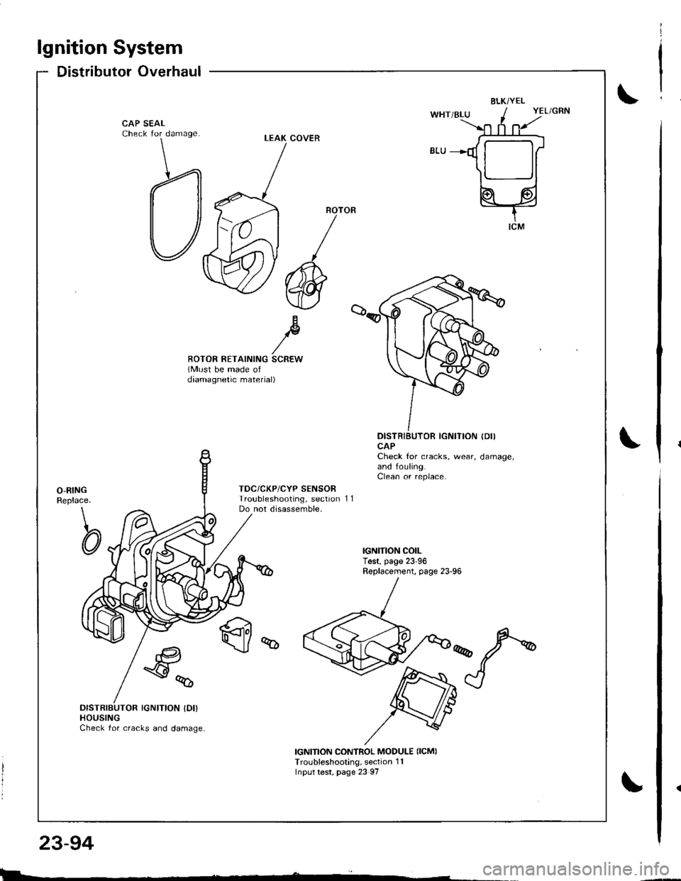
lgnition System
Distributor Overhaul
BLKi YEL
CAP SEALCheck for damage
Bp//ROTOR RETAINING SCREW(Must be made ofdaamagnetic material)
DISTRIBUTOR IGNITION (DII
CAPCheck for cracks, wear, damage,and fouling.Clean or replace.
O-RINGReplace.
\
CI
TDC/CKP/CYP SENSORTroubleshooting, sectionDo not disassemble,11
q
€a
\y%
DISTRIBUTOR IGNITION IDI)HOUSINGCheck for cracks and damage,
IGNITION CONTROL MODULE {ICMITroubleshooting, section 1 1Input test, page 23 97
LEAK COVER
l
I
I
|>l
Page 1152 of 1681
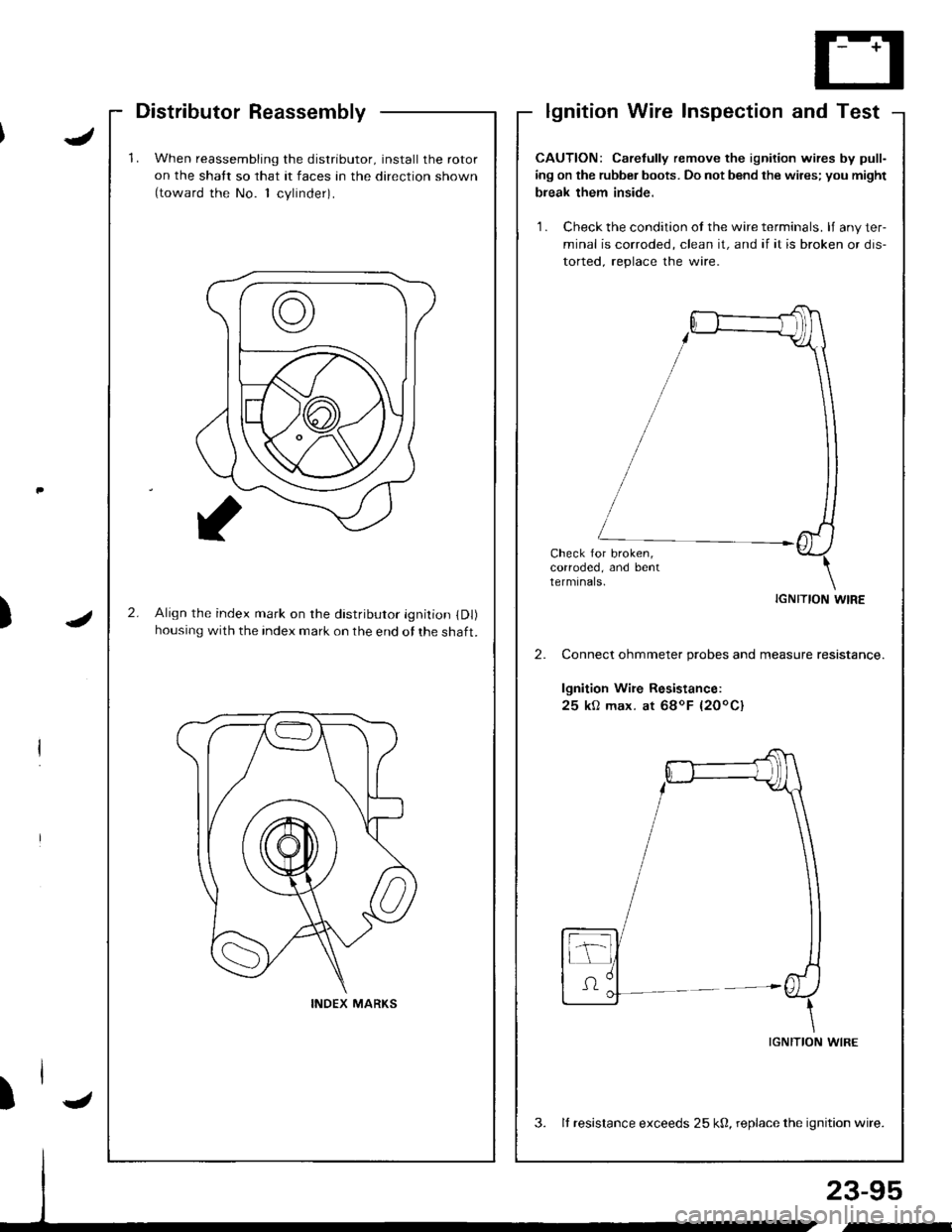
'1.When reassembling the distributor, install the rotor
on the shatt so that it faces an the direction shown(toward the No. 1 cvlinder).
2.Align the index mark on rhe distributor ignition (Dl)
housing with the index mark on the end of the shaft.
INDEX MARKS
Distributor Reassemblylgnition Wire Inspection and Test
J
J)
23-95
,-
CAUTION: Carelully remove the ignition wires by pull-
ing on the rubber boots. Do not bend the wires; you might
break them inside.
'1 . Check the condition ot the wire terminals. lJ any ter-
minal is corroded, clean it, and if it is broken or dis-
torted. reolace the wire.
Check for broken,corroded, and bentterminals.
IGNITION WIRE
Connect ohmmeter probes and measure resistance.
lgnition Wire Resistance:
25 kO max. at 68oF {20oC}
IGNITION WIRE
3. It resistance exceeds 25 k0, replace the ignition wire.
)l-
Page 1153 of 1681
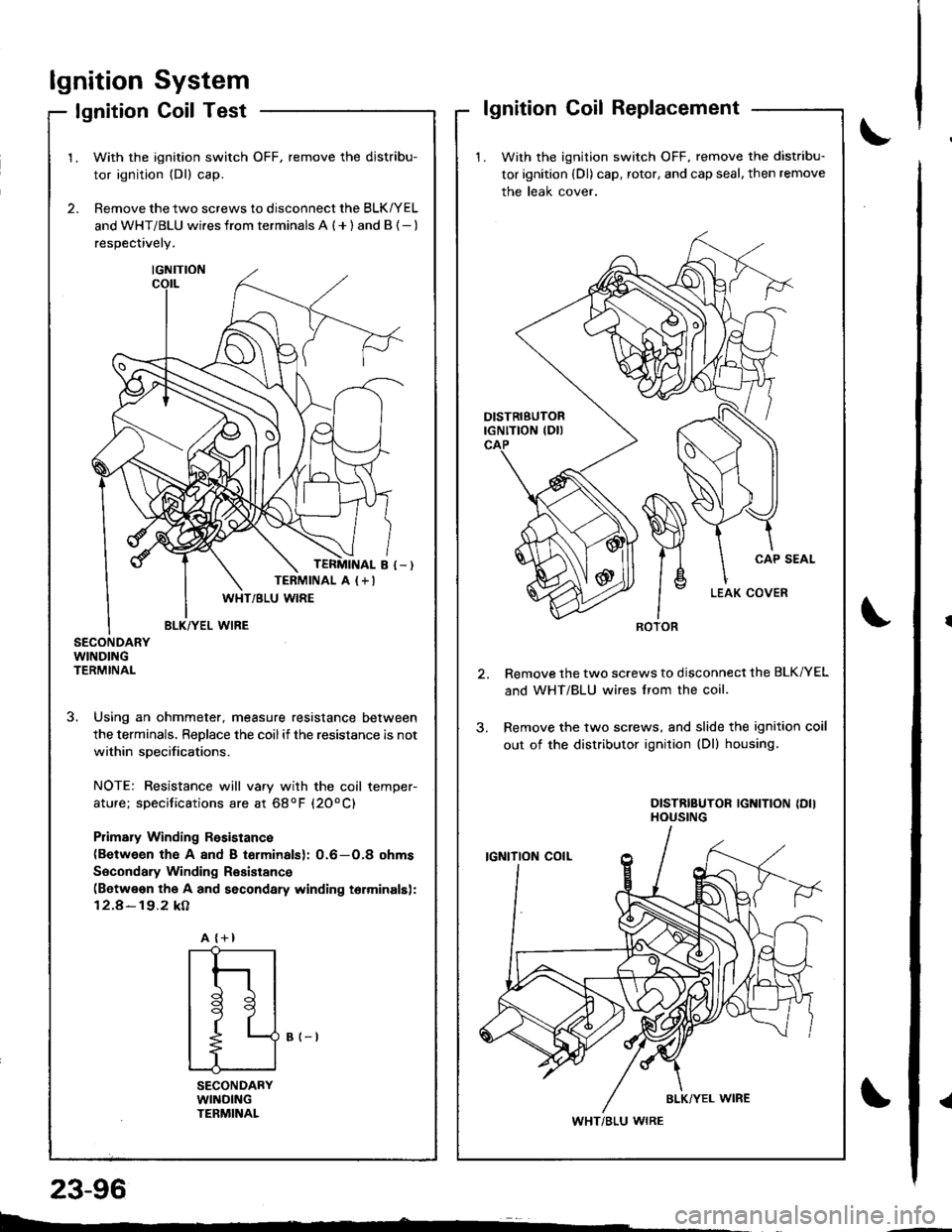
lgnitionSystem
Coil TestlgnitionlgnitionCoilReplacement
1. With the ignition switch OFF, remove the distribu-
tor ignition (Dl) cap, rotor, and cap seal, then remove
the leak cover.
Remove the two screws to disconnect the BLK/YEL
and WHT/BLU wires lrom the coil.
Remove the two screws, and slide the ignition coil
out of the distributor ignition (Dl) housing.
DISTRIBUTOR IGNITION {DIIHOUSING
ROTOR
WHT/BLU WIRE
2.
1.With the ignition switch OFF, remove the distribu-
tor ignition (Dl) cap.
Remove the two screws to disconnect the BLK/YEL
and WHT/BLU wi.es from terminals A ( + ) and B {- )
respectively.
SECONDARYWINDINGTERMINAL
3. Using an ohmmeter, measure resistance between
the terminals. ReDlace the coilif the resistance is not
within soecifications.
NOTE: Resistance will vary with the coil temper-
ature; specifications are at 68oF (20oC)
Plimary Winding Rssistance(Between th€ A 8nd B torminalsl: 0.6-O,8 ohms
Socondary Winding Resistance(Betwe€n the A and secondary winding torminalsl:
12.4-19.2 kA
B (-t
SECONDARYWllrlDlNGTENMINAL
TERMINAL A (+I
A {+}
{
t
l
tl
t9
t
L--
23-96
Page 1430 of 1681
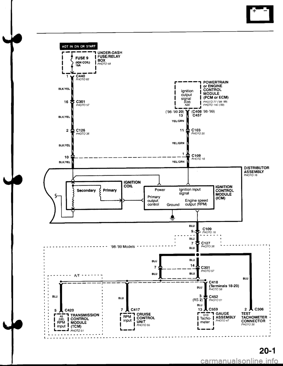
UNDER-DASHFUSE/RELAYBOX
c301
c126
POWERTRAINor ENGINE
F,ltffi lialEE:;hfui | (PcM or EcM)
alcM) | PHaraTT lga 99)| 420 | PHA|A t4A t00i
(98 s9 20) Y (C408 98- s9)13 ll c457
YEUGFN
o
'98-'99 Models
BL{J
7
ALU
c103
cl 09
DISTRIBUTORASSEMBLY
c418(Terminals 18-20)
c452
cl27
BU'
9.
BLU
7BLU
'd
c301
JI
'"'fil
TESTr-]i.I GAUGE
lraiii'o l3,sseqarv
lmerer | --TACHOMETERCONNECTOR
IGNITIONcolLPower lgnition inputslgnalPrimaryoutout Enqine soeedcoritrol cround ouiaut (RPM)
20-.,l
Page 1437 of 1681
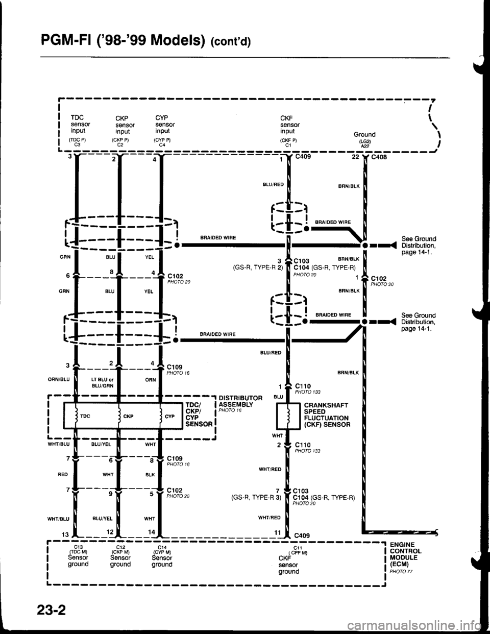
PGM-FI ('98-'99 Models) (conrd)
lt
TDC CKP CYP CKF TSenSOr SenSOr SenSOr SenSOr \inpul input input input cround I(t?:") (c[!P) ("I:n (cKF P) ttg i
a----_-----'
OFN/BIU T ..I,�i#IOBN
4-fi_+:--ffi;;**
f------{:::tl BFA'bE'w'�RF
[--{-'-'-<
'l$i"lr'
,f:-i1f;"-l
i
t ? "";t3,r
Ses Ground
BFN/BLK
! -TDC/ | ASSEMBLY Ff1 cnaHrsxlrrDISTRIBUTOR BLU-I TDC/ I ASSEMBLY I'
^-" 195!/ lPHofol6 I
"Jt
t:f--tir*,,
*",":1"""'"'"='F--+--,{r*,,,o,,'^,,..,r,fi81q1,o.,
".,,..,
iil
23-2
Page 1446 of 1681
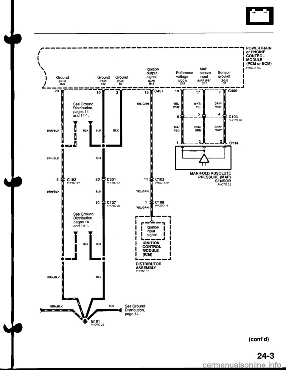
lgnition MAP
d',rtput Rsfetenag sensor Sensor
I Ground Ground Groud signal vollago input ground
: rLGl) (r,Gzl rpclr rtcM) (vccl) {MAP eB) (sG1)I B2o Blo 82 413 c19 c17 c7
I
I
\
MANIFOLD ABSOLUTEPRESSURE (MAP)SENSOR
POWERTRAINor ENGINECONTROLMODULE(PCM o. ECM)
c102c301
c127i[::
YEUGRN
See GroundDistribution,paos 14.
10
See GroundDistribution,pages !4and 1+1.
-i
"L
:p
I lg:Ll- I
I ii5ilr I
lGNtTtot{coxTnolMODULf
0cM)L-----J
DISTRIBUTORASSEMBLY
(cont'd)
24-3
Page 1456 of 1681
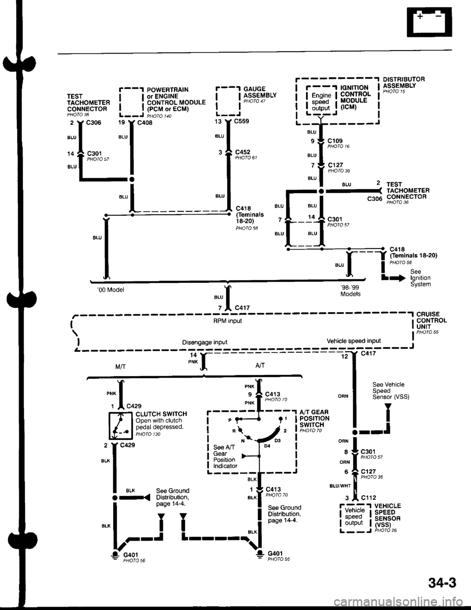
r--1 caucE I r--'t lGNlnoN
,l;:
DISTRIBUTORASSEMBLY
TESTTACHOMETERCONNECTOB
r--1 POWERTRAINTEST I lorENGlNETACHoMETER I I coNTRoL MoDULECONNECTOR | | (PCM or ECM)PHO|Q 36 L--J PHO\O 1aA
.:r"'' ::"r**
..1^"^, I
.-,1 ilo-;52 I*
l-!
t*"L________
l__j**" ililf,fj$8Blt?'; -^;." ! Y-I-- --'-r-----
.,,,I BLU I*-l s:a c1o9
. I "or, --.f r;'orc 'o
9,^::,,, ";f
t'ot'"
'ls":/",
Btu I aLU 2
---
"., I *, I
c3o6
!!",?ii:" 'l--.4n+,.
-"1--:1"-l
'00 Model"il
".',-- -'l cRUlsE
I RPtvl input I CONTROLI UNIT
Models
lPHora 55
I oisengage input Vehicle speed input rL - - - - - - - -*? =_-_-_-_-_-:_-_-_== = =_-_;ffcr--r i
M/r PNKI Air I; "Hf----;---
,
---.tf c417
*f "n^f
""" I :ffs:"ff:,
*oa,,"",*,,"",.---:l[i:].', uo-u=uo
/.1ff;i;lu:*r |
""!-
ii iit'diF' !--l
":"1",,,
"i-f t* ' """1 :ffs:"ff;
,.[:..
i'*f-i
li*'
I oaoe ,+ +
I ftf,ll,*r i;p-pT l ;.#i""�J:*^l
i i "'*l L'itliY#;"
b;'t
t----'{
non-,: pHOTO 56 - PHOTO 56
34-3
Page 1500 of 1681
Gauges (cont'd)
- How the Circuit Works
When the ignition switch is in ON (ll) or START (lll),
battery voltage is supplied through fuse 25 to the
gauges in the gauge assembly.
Speedometer and Odometer
The odometer and speedometer drive circuits
receive pulses lrom the vehicle speed sensor
(VSS). The pulse rate increases as the car
accelerates. The frequency and duration of these
input pulses are measured and displayed by the
speedometer, odometer and tripmeter.
Tachometer ('98-'99 Models)
The tachometer drive circuit receives oulses from
the ignition control module (lCM) in the distributor
assembly. The solid-state tachometer then displays
these pulses as engine speed. For each 200 pulses
per minute from the ignition control module (lCM),
the tachometer displays 100 RPM.
Tachometer ('00 Model)
The tachometer drive circuit receives pulses f rom
the PCM or ECM. The solid-state tachometer then
displays these pulses as engine speed. For each
200 oulses oer minute trom the PCM or ECM the
tachometer displays 1 00 RPM.
Engine Coolant Temperature Gauge and Fuel
Gauge
The engine coolant temperature gauge has two
intersecting coils wound around a permanent
magnet rotor. Voltage applied to the coils, through
fuse 25, generates a magnetic field. The magnetic
field, controlled by the engine coolant temperature
gauge sending unit, causes the rotor to rotate and
the gauge needle to move. As the resistance in the
sending unit varies, current through the gauge coils
changes. The gauge needle moves toward the coil
with the strongest magnetic tield. The fuel gauge
works the same way.
The engine coolant temperature gauge sending
unit's resistance varies from about 137 ohms at low
engine temperature to between 30-46 ohms at high
temperature (radiator fan running).
The fuel gauge sending unit's resistance varies from
about 2-5 ohms at full, to about 110 ohms at empty.
When you turn the ignition switch to LOCK (0), the
gauge remains at the last reading until you turn lhe
ignition switch to ON (ll) or START (lll) again.
Refer to the Service Manual (Section 23, Electrical)
for specific tests or troubleshooting procedures.
81'2