suspension HONDA INTEGRA 1998 4.G Owner's Manual
[x] Cancel search | Manufacturer: HONDA, Model Year: 1998, Model line: INTEGRA, Model: HONDA INTEGRA 1998 4.GPages: 1681, PDF Size: 54.22 MB
Page 750 of 1681

Rear Damper
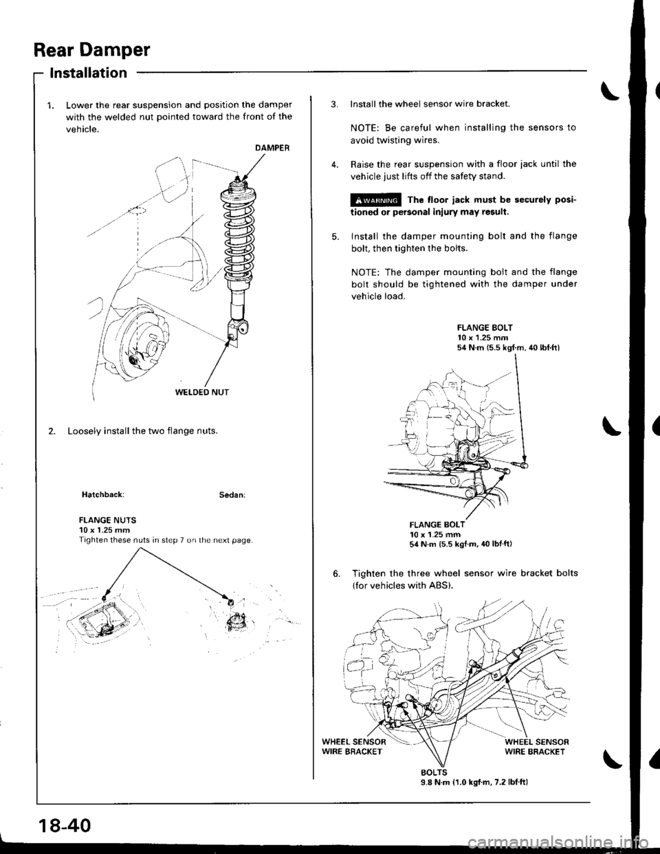
Lower the rear suspension and position the damper
with the welded nut pointed toward the front of the
vehicle.
DAMPER
2. Loosely install the two flange nuts.
Hatchback:Sedan:
lnstallation
. ',.?7,:..r9\,ir '..
EY
FLANGE NUTS10 x 1.25 mmTighten these nuts in step 7 on the next page.
18-40
3. Install the wheel sensor wire bracket.
NOTE: Be careful when installing the sensors to
avoid twisting wires.
Raise the rear suspension with a floor iack until the
vehicle just lifts off the safety stand.
@ The floor jack must be securely posi-
tionod or personal iniury may result.
5. Install the damper mounting bolt and the flange
bolt, then tighten the bolts.
NOTE: The damper mounting bolt and the flange
bolt should be tightened with the damper under
vehicle load.
FLANGE EOLT10 x 1.25 m.n54 N.m (5.5 kgf m, 40 lbt.ftl
FLANGE BOLT10 x 1-25 mm54 N.m ls.s kgf m, 40 lbtft)
6. Tighten the three wheel sensor wire bracket bolts
{for vehicles with ABS).
9.8 N.m {1.0 kg{.m, 7.2 lbtftlBOLTS
Page 814 of 1681

ABS Control Unit
RemovaUlnstallation
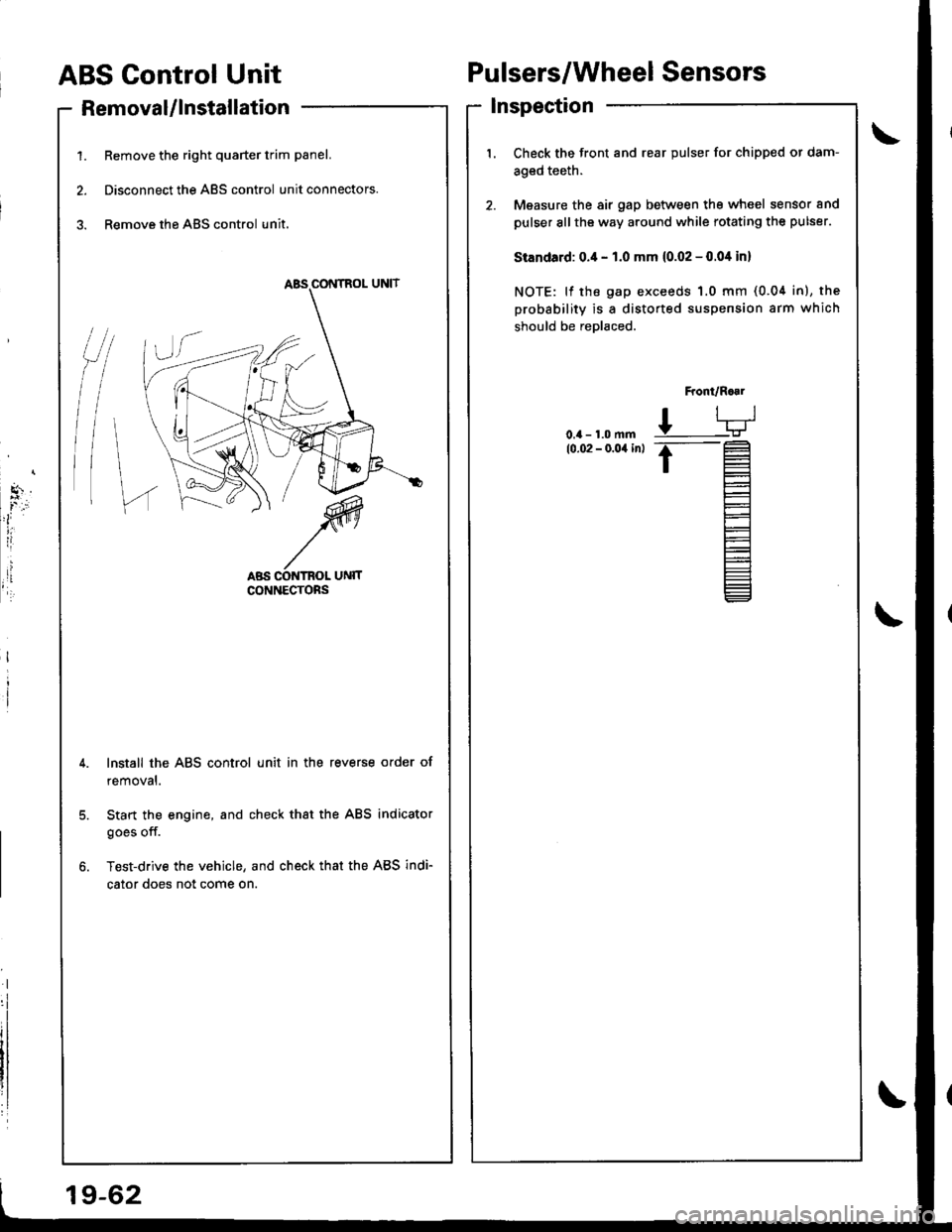
1. Remove the right quarter trim panel.
2. Disconnect the ABS control unit connectors.
3. Remove the ABS control unit.
Pulsers/Wheel Sensors
Inspection
/t
l\
I
Check the front and rear pulser for chipped or dam-
aged teeth.
Measure the air gap between tho wheel sensor and
pulser sllthe way around while rotating the pulser.
Standard: 0.4 - 1.0 mm (0.02 - 0.04 in)
NOTE: lf the gap exceeds 1.0 mm (0.04 in), the
probability is a distorted suspension arm which
should be reDlaced.
Front/R..1
L-TJ
.t-
t=
l-
Et-E_
Install the ABS control unit in the reverse order of
removal.
Start the engine, and check that the ABS indicator
goes off.
Test-drive the vehicle, and check that the ABS indi-
cator does not come on.
19-62
Page 1655 of 1681

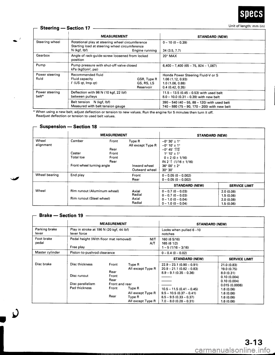
MEASUREMENTSTANDARD (NEWI
Steering wheelRotational play at steering wheel circumferenceStarting load at steering wheel circumferenceN (kgf, lbf) Engine running
0 - 10 (0 - 0.39)
34 (3.5,7 .71
GearboxAngle of rack-guide-screw loosened from lockedoosition20'MAX
PumpPump pressure with shut-off valve closedkPa (kgf/cm,, psi)6,400 - 7,400 (65 - 75, 924 - 1,067],
Power steeringfluidRecommended fluidFluid capacity GSR, Type Rf (US qt, lmp qtl cS, RS, LSReservoir
Honda Power Steering Fluid-V or S1.06 (1.12,0.93)
1.0 (1.06,0.88)
0.4 (0.42, 0.35)
Power steeringbelt*Deflection with 98 N (10 kgf,22 lbflbetween pulleys1 1.5 - 13.5 (0.45 - 0.531 with used belt8.0 - 10.0 (0.31 - 0.39) with new belt
Belt tension N (kgf, lbf)Measured with belt tension gauge390 - 540 (40 - 55, 88 - 120) with used belt740 - 880 (75 - 90, 170 - 2001with new belt
SteeringSection 17
* When using a new belt, adjust deflection or tension to new values. Run the engine for 5 minutes then turn it off.Readiust deflection or tension to used belt values.
Suspension - Section 18
BrakeSection 19
Unit of length: mm (in)
$t
MEASUREMENTSTANDARD (NEWI
WheelalignmentCamber Front Type RAll except Type RRearCaster FrontTotal toe FrontRearFront wheel turning angle Inward wheelOutward wheel
-0'30'r 1"-0' 10'r 1.-0" 45'�1?:i3i1. 10'�1 1.0!210!1116!,lN 2 lf (t7t6 1 1716136. 00'1 2"30'30'
Wheel bearingEnd play FrontRear0 - 0.05 (0 - 0.002)0 - 0.05 (0 - 0.002)
WheelRim runout (Aluminum wheel) AxialRadialRim runout (Steel wheel) AxialRadial
STANDARD (NEW}SERVICE LIMIT
0 - 0.7 (0 - 0.03)0 - 0.7 (0 - 0.03)0 - 1.0 (0 - 0.04)0 - 1.0 (0 - 0.04)
2.0 (0.08)
1.5 (0.06)2.0 (0.08)1.5 (0.06)
MEASUREMENTSTANDARD (NEW}
Parking brakeleverPlay in stroke at 196 N (20 kgf,44 lbf)lever forceLocks when oulled 6 -10
notches
Foot brakepedalPedal height (With floor mat removed)
Free play
M/TAtT160 (6 5/161165 rc 1nl1-5(1/16-3/16)
Master cylinderPiston-to-oushrod clearance0 - 0.4 (0 - 0.021
Disc brakeDisc thickness Front Type RAll except Type RRearDisc runout FrontRearDisc parallelism Front and rearPad thickness Front Type R
All except Type RRear Type RAll except Type R
STANDARD (NEWISERV]CE LIMIT
22.9 - 23.1 (0.90 - 0.91120.9 - 21.1 (0.82 - 0.83)
1= t (0.35-0.361
10.5 - 11.5 (0.41 - 0.45)9.5 - 10.5 (0.37 * 0.41)8.5 - 9.5 (0.33 - 0.37)7.0 - 8.0 (0.28 - 0.31)
21.0 (0.83)19.0 (0.75)
8.0 (0.31)
0.10 (0.004)
0.10 (0.004)
0.015 (0.0006)1.6 (0.06)
1.6 (0.06)1.6 (0.06)
1.6 (0.06)
Page 1658 of 1681

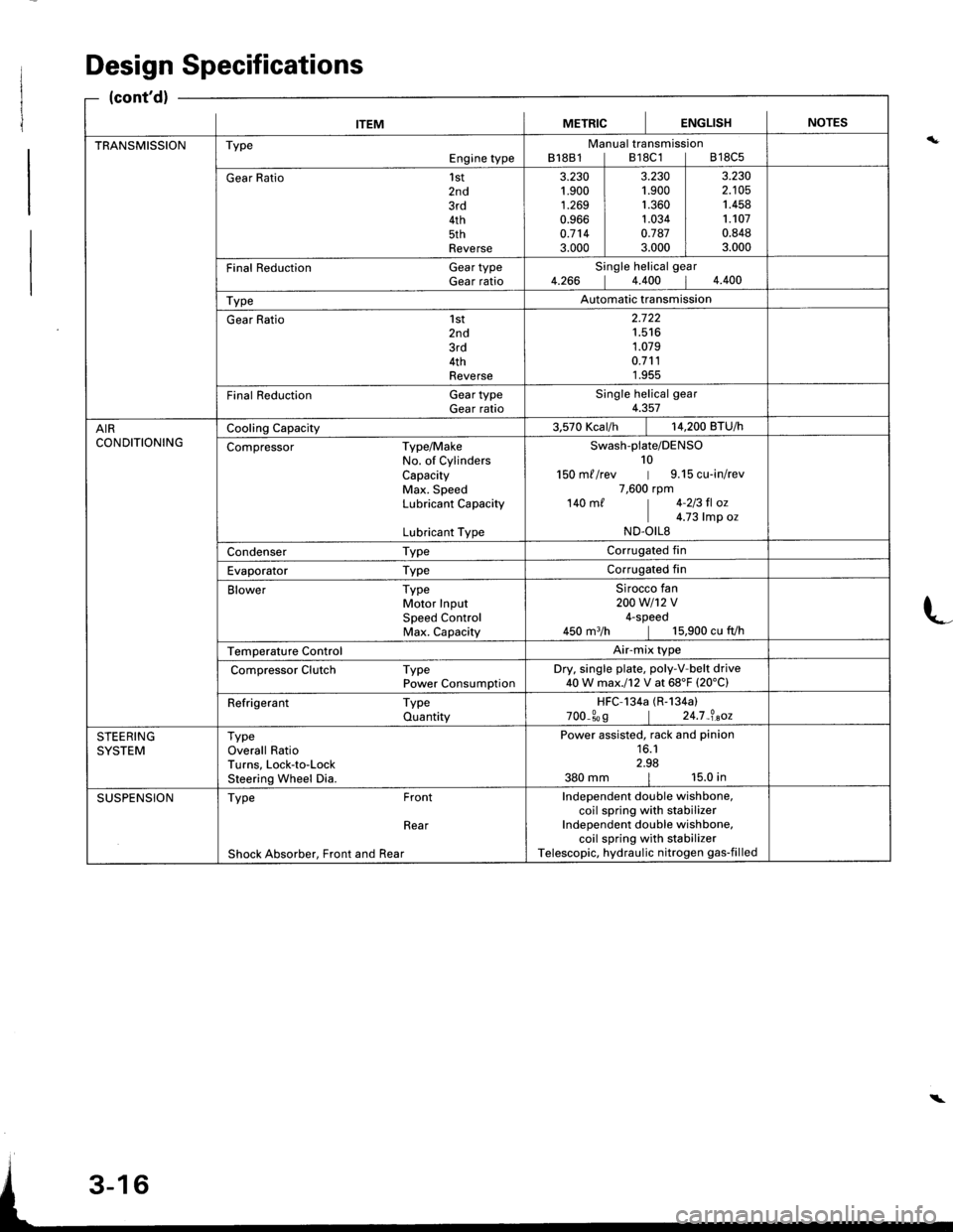
ITEMMETRICIENGLISHINOTES
TRANSMISSIONTypeEngine typeManual transmissionB18B1lB18C1lB18C5
Gear Ratio1st2nd3rd4th5thReverse
3.230't.900
1.2690.9660.7143.000
3.2301.9001.3601.0340.7873.000
3.2302.1051.4581.1070.8483.000
Final Reduction Gear typeGear ratioSingle helical gear4.266 14.400 14.400
TypeAutomatic transmission
Gear Ratio 1st2nd3rd4thReverse
2.722't.516
1.0790.7111.955
Final Reduction GeartypeGear ratioSingle helical gear4.357
AIRCONDITIONINGCooling Capacity3.570 Kcar/h | 14,200 BTU/h
Compressor Type/MakeNo. of CylindersCapacityMax. SpeedLubricant Capacity
Lubricant Type
Swash-plate/DENSO10150 m//rev | 9.15 cu-in/rev7,600 rpm140 m/ | 4-213 fl oz
I c.z3 |rp o.ND.OILS
Condenser TypeCorrugated fin
Evaporator TypeCorrugated fin
Blower TypeMotor InputSpeed ControlMax. Capacity
Sirocco fan200w1't2v4-speed450 m3/h | 15,900 cu fVh
Temperature ControlAir-mix type
Compressor Clutch TypePower ConsumptionDry. single plate, poly-V-belt drive40W max.l12 V at 68'F (20'C)
Refrigerant TypeQuantityHFC-134a (R-134a)
700_309 | 24.7_?.aoz
STEERINGSYSTEMTypeOverall RatioTurns, Lock-to-LockSteering Wheel Dia.
Power assisted, rack and pinion16.12.98380 mm | 15.0 in
SUSPENSIONType Front
Rear
Shock Absorber, Front and Rear
Independent double wishbone,coil spring with stabilizerIndependent double wishbone,coil spring with stabilizerTelescopic, hydraulic nitrogen gas-filled
Design Specifications
(cont'd)
L
\