headlight bulb HONDA INTEGRA 1998 4.G Workshop Manual
[x] Cancel search | Manufacturer: HONDA, Model Year: 1998, Model line: INTEGRA, Model: HONDA INTEGRA 1998 4.GPages: 1681, PDF Size: 54.22 MB
Page 1217 of 1681
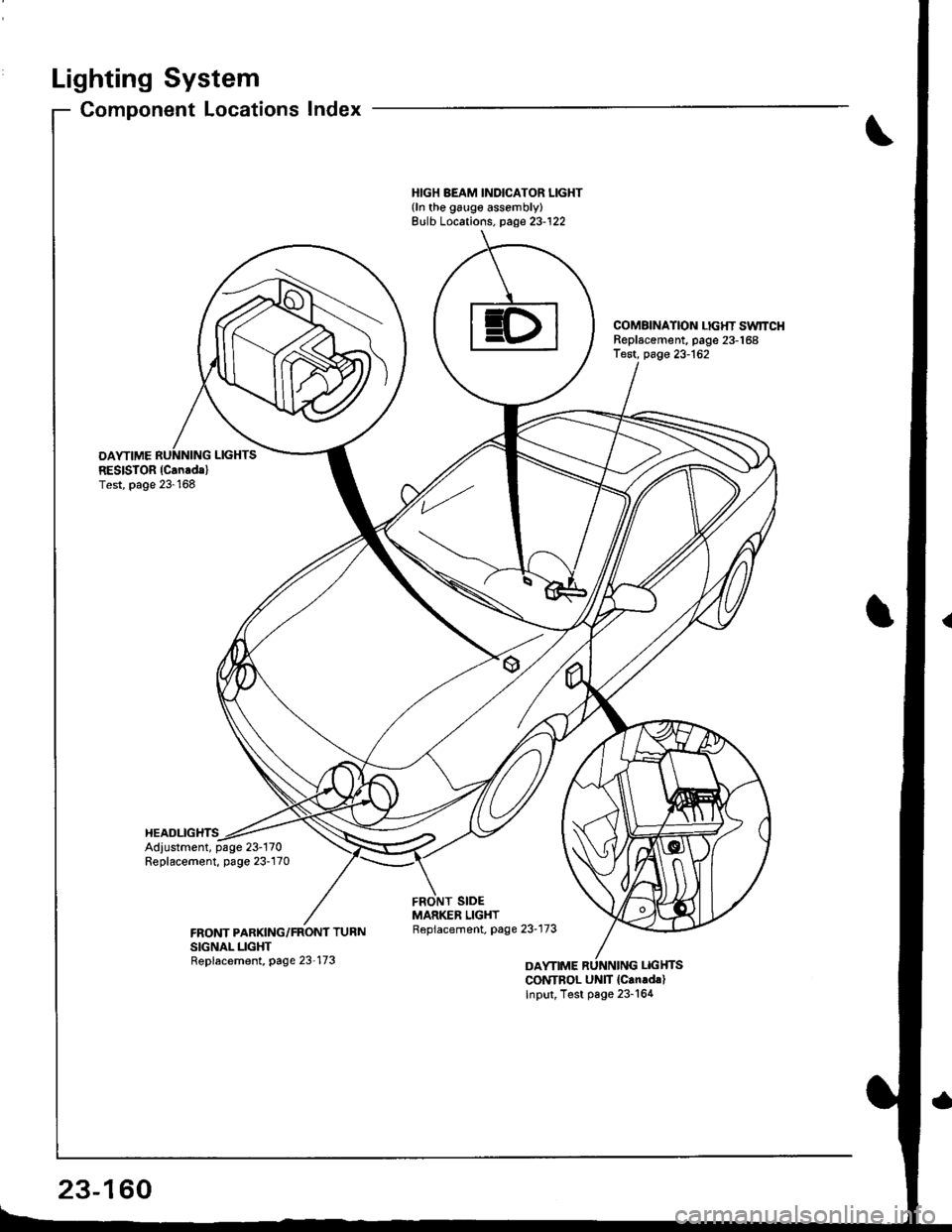
Lighting System
OAYTIMERESISTOR (Can.dal
Test, page 23-168
HEADLIGHTS
Component Locations Index
HIGH BEAM INDICATOR LIGHT{ln the galge assembly}Bulb Locations. page 23-122
COMAINATION LIGHT SwlTCHReplscement, page 23-168Test, page 23-162
Adjustment, page 23-170Replacement, page 23-170
CONTBOL UNIT {Can.d.)Input, Test page 23-164
23-160
Page 1222 of 1681
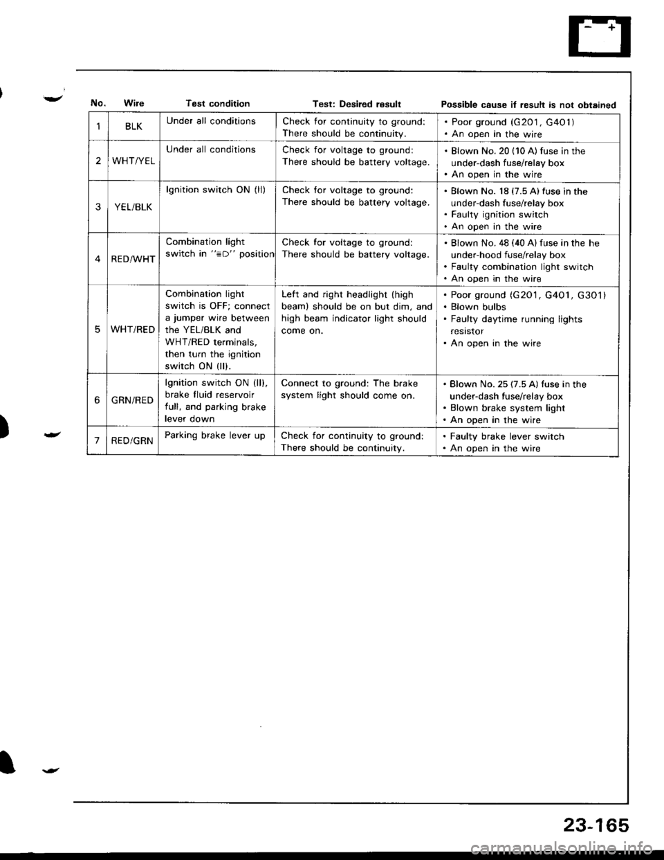
Tsst conditionTest: Desiled resultPossible cause it result is not obtained
)
BLKUnder all conditionsCheck for continuity to ground:
There should be continuity.
. Poor ground (G201 , G40l ). An open in the wire
2WHT/YEL
Under all conditionsCheck for voltage to ground:
There should be battery voltage.
. Blown No. 20 (10 A) fus€ in the
under-dash fuse/relay box. An open in the wire
YEL/BLK
lgnition switch ON (ll)Check for voltage to ground:
There should be battery voltage.
Blown No. 18 (7.5 A)fuse in the
under-dash fuse/relay box
Faulty ignition switch
An open in the wire
RED/WHT
Combination light
switch in "=D" position
Check for voltage to ground:
There should be battery voltage.
Blown No. 48 (40 A) fuse in the he
under-hood fuse/relay box
Faulty combination light switch
An open in the wire
WHT/RED
Combination light
switch is OFF; connect
a jumper wire between
the YEL/BLK and
WHT/RED terminals,
then turn the ignition
switch ON (ll).
Left and right headlight (high
beaml should be on but dim, and
high beam indicator light should
come on.
Poor ground (G20'1, G4O1, G301)
Blown bulbs
Faulty daytime running lights
resrstor
An open in the wire
6GRN/RED
lgnition switch ON (ll).
brake fluid reservoir
full, and parking brake
levef oown
Connect to ground: The b.ake
system light should come on.
Blown No. 25 (7.5 A) fuse in the
under-dash fuse/relay box
Blown brake system light
An open in the wire
'1RED/GRNParking brake lever upCheck for continuity to ground:
There should be continuity.
. Faulty brake lever switch. An open in the wire
23-165
Page 1226 of 1681
)
Headlight
Description
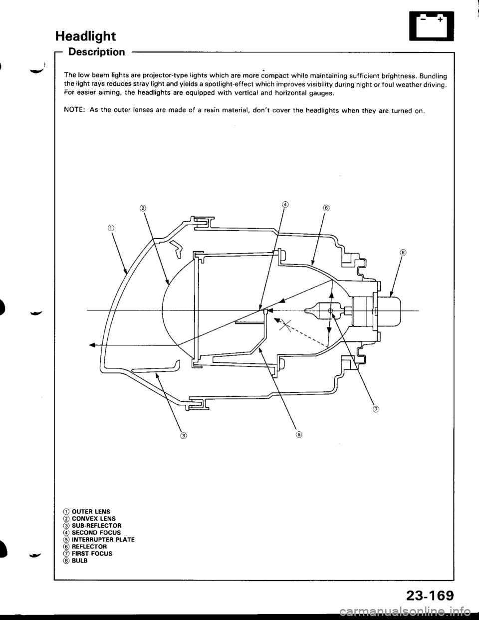
The low beam lights are projector-type lights which are more compact while maintaining sufticient brightness. Bundlingthe light rays reduces stray light and yields a spotlight-effect which improves visibility during night or foul weather driving.For easier aiming, the headlights are equipped with vertical and horizontal gauges.
NOTE: As the outer lenses are made of a resin material, don't cover the headlights when they a.e turned on.
OUTER LENSCONVEX LENSSU8-REFLECTORSECOND FOCUSINTERRUPTER PLATEREFLECTORFIRST FOCUSBULB
23-169
Page 1229 of 1681
Headlight
Headlight Replacement
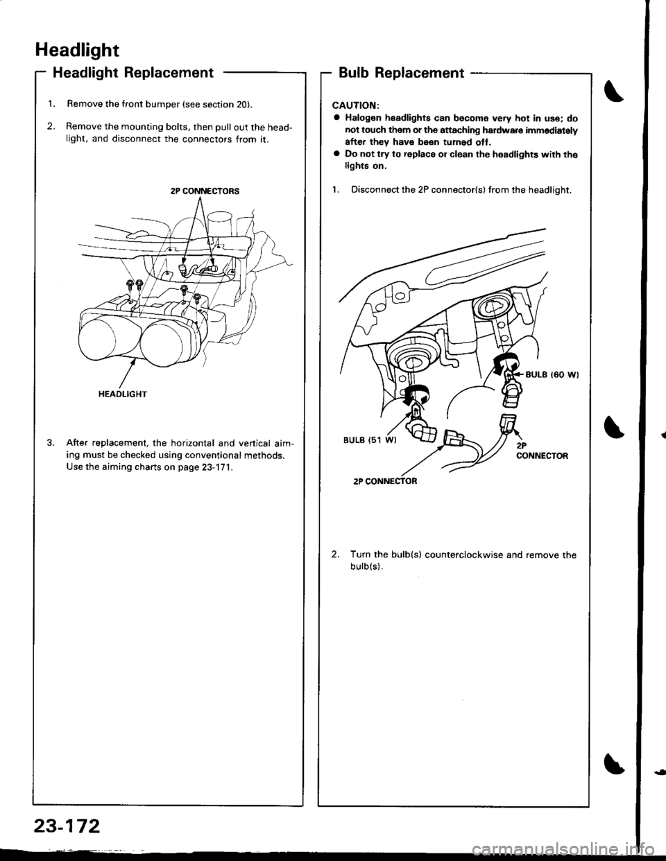
1. Remove the front bumper (see section 20).
2. Remove the mounting bolts, then pull out the head-
light, and disconnect the connectors from it.
After replacement, the horizontal and venical aim-
ing must be checked using conventional methods.
Use the aiming charts on page 23-171.
Bulb Replacement
CAUTION:
a Halogen headlights can becomo very hot in use; do
not touch them or the attaching haldware imm6diately
after they have been tuh6d ott.a Do not try to replace or cl6an the headlights with tho
lights on.
1. Disconnect the 2P connector(s) from the headlight.
Turn the bulb(s) counterclockwise and remove the
bulb(s).
2P CONNECTORS
HEADLIGHT
2PCONNECTOR
2P CONNECTOR
23-172
Page 1504 of 1681
- How the Circuit Works
With the ignition switch in ON (ll) or START (lll),
voltage is applied to the A,/T gear position indicator.
The A,/T gear position switch provides a ground for
each position. As an input is grounded, ils indicator
light comes on. lf you se,ecl B, tor example, ground
will be applied to the input of the A,/T gear position
indicator, and the R indicator bulb will come on.
With the headlight switch in PARK or HEAD, voltage
is applied to the RED/BLK wire terminal. this
changes the indicator panel illumination from lixed
to controlled by the dash lights dimmer inpul
through the RED wire.
When the lransmission ('98.�99 models) or
powertrain ('00 model) control module (TCM or
PCM) detects an abnormality in the automatic
transmission control system, or when you request
diagnostic trouble codes through the service
check connector, the TCM or PCM will make lhe D4
indicator light blink.
Refer to the Service Manual (Section 14,
Automatic Transmission) for soecific tests or
troubleshooting procedures.
89-1