tires HONDA INTEGRA 1998 4.G Workshop Manual
[x] Cancel search | Manufacturer: HONDA, Model Year: 1998, Model line: INTEGRA, Model: HONDA INTEGRA 1998 4.GPages: 1681, PDF Size: 54.22 MB
Page 667 of 1681

Inspection and Adjustment
Steering Operation
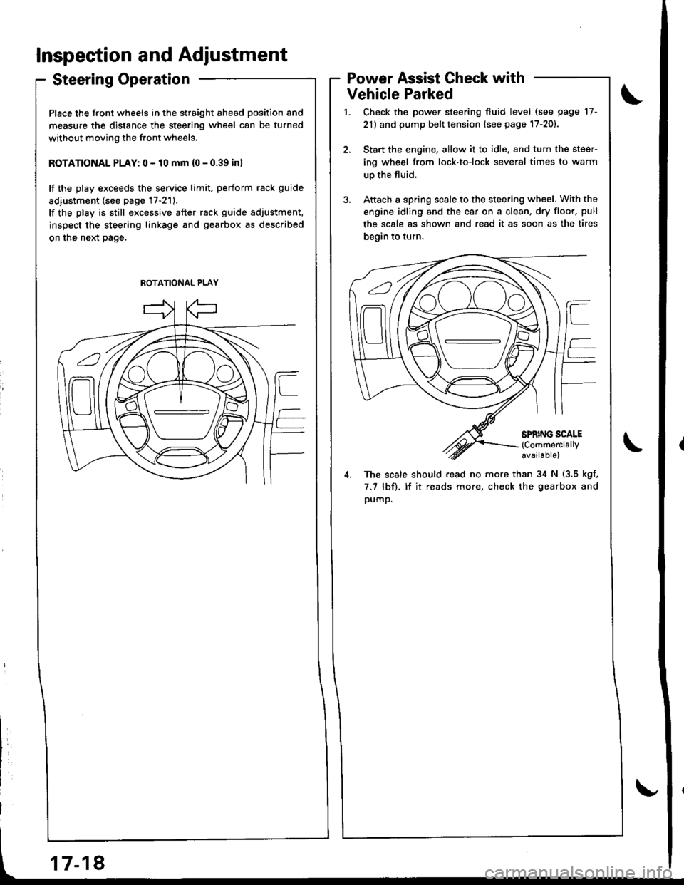
Place the front wheels in the straight ahead position and
measure the distance the steering wheel can be turned
without moving the front wheels.
ROTATIONAL PLAY: 0 - 10 mm {0 - 0.39 inl
lf the play exceeds the service limit. perform rack guide
adiustment (see page 17-211.
lf the play is still excessive after rack guide adjustment.
inspect the steering linkage and gearbox as described
on the neld page.
Power Assist Check with
Vehicle Parked
Check the power steering fluid level (see page 17-
21) and pump belt tension (see page 17-201.
Start the engine, allow it to idle. and turn the steer
ing wheel from lock-to-lock several times to warm
up the fluid.
Attach a spring scale to the steering wheel. With the
engine idling and the car on a clean. dry floor. pull
the scale as shown and read it as soon as the tires
begin to turn,
4. The scale should read no more than 34 N (3.5 kgf,
7.7 lbf). lf it reads more, check the gearbox and
pump.
ROTATIONAL PLAY
Page 714 of 1681

Wheel Alignment
Caster
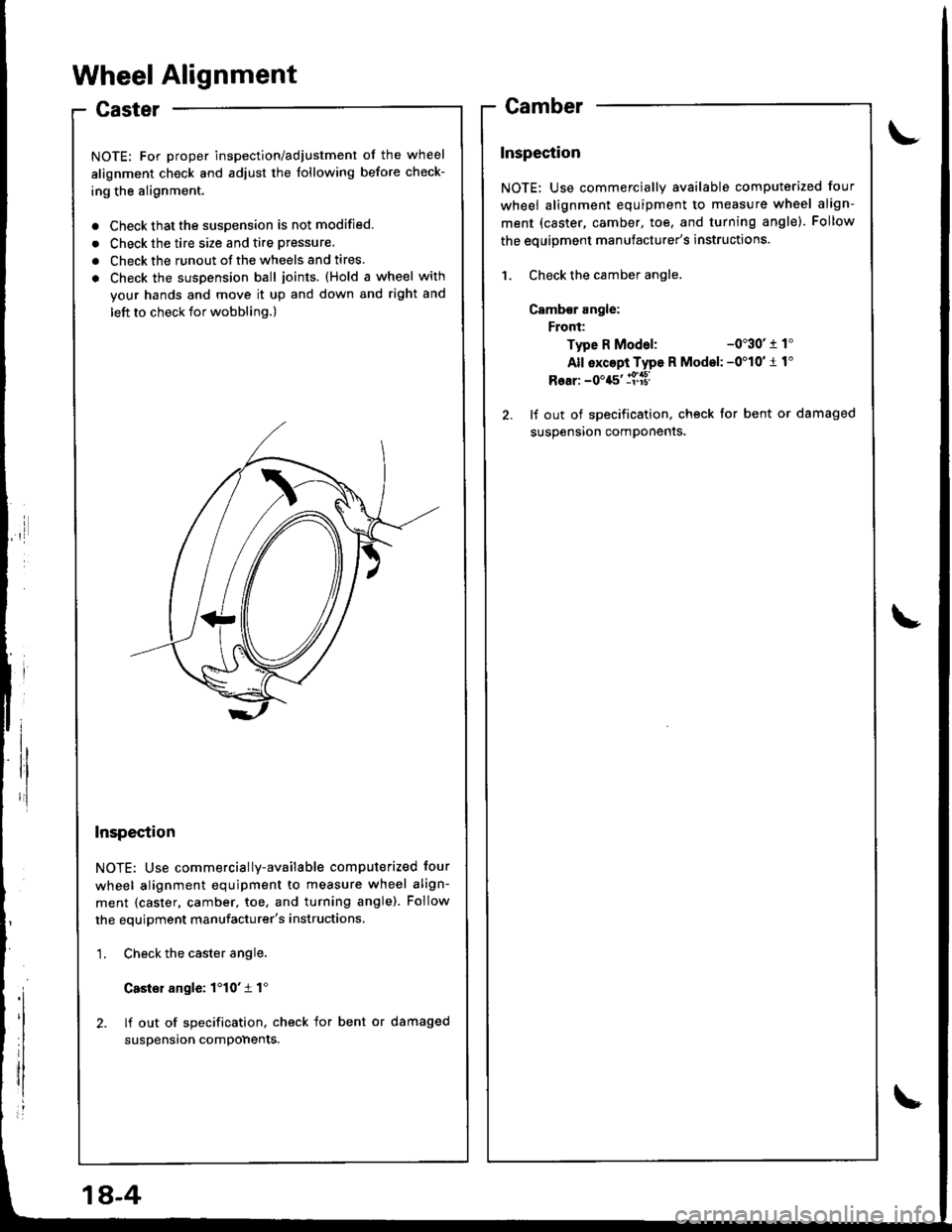
NOTE: For proper inspection/adjustment of the wheel
alignment check and adjust the following before check-
ing the alignment.
. Check that the susoension is not modified.
. Check the tire size and tire pressure.
. Check the runout of the wheels and tires.
. Check the suspension ball joints. (Hold a wheel with
your hands and move it up and down and right and
left to check tor wobbling.)
Inspection
NOTE: Use commercially-available computerized four
wheel alignment equipment to measure wheel align-
ment {caster, camber, toe, and turning angle). Follow
the equipment manufacturer's instructions.
1. Check the caster angle.
Casler angle: 1'10't 1"
2. lf out of specification. check for bent or damaged
suspension compohents.
Camber
Inspection
NOTE: Use commercially available computerized four
wheel alignment equipment to measure wheel align-
ment (caster, camber, toe, and turning angle). Follow
the eouioment manufacturer's instructions.
1. Check the camber angle.
Camb€r angle:
Front:
Type R Modal:-0"30' r 1'
All exc6pi Type R Model: -0'10'1 1"
Rear: -0'45' ll['a8l
2. lf out of specification, check for bent or damaged
susoension comDonents.
1A-4
Page 778 of 1681

.,i
,I
Anti-lock Brake SYstem (ABS)
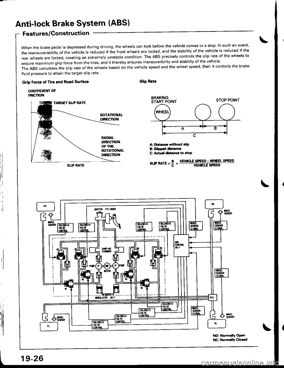
when the brake pedal is depressed during driving, the wheels can lock before the vehicle comes to a stop. In such an event.
the maneuverability of the vehicle is reduced if the front wheels are locked, and the stability of the vehicle is reduced if the
rear wheels are locked, creating an extremely unstable condition. The ABS precisely controls the slip rate o{ the wheels to
ensUre maximum grip force from the tires, and it thereby ensures maneuverbiIity and stabiIity of the vehicIe.
The ABS calculates the slip rate of the wheels based on the vehicle speed and the wheel speed. then it controls the brake
fluid oressure to attain the target slip rate
Features/Gonstructio n
Grip Foact ot Ti.c tnd Rotd Surfuco
COEFFICIEUT OFFNIG"TPN
Slip Rrtr
BRAKINGSTART POINT
i'l
A: f'3t rp withoul .lip
B: SIDp.d dirt.nc.G Actu.ldtt nc.io.top
sr.n arrr = f =
STOP POINTTARGET SUP RATE
SUP FATEVEHICT.C S'EEO - wlCEL SPEED
NO: Notm.lly oP.n
l{C: Noirnrly qo..d
19-26
Page 1659 of 1681

:/
*1: RS*2: LS, GS, GS.R, TYPE R*3: RS+4: TYPE R*5: Except high mount brake light installed in rear spoirer.
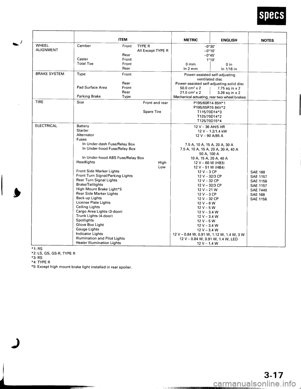
ITEMMETRICENGLISHNOTES
WHEELALIGNMENTCamber Front TYPE RAll Except ryPE RRearCaster FrontTotal Toe FrontRear
-0"30'_0"10,_0"45'
1"10'omm I oinIn 2 mm I In 1/16 inBRAKE SYSTEMType Front
RearPad Surface Area FrontRearParking Brake Type
Power-assisted self-adjustingventilated discPower-assisted self-adlusting sol id disc50.0 cm2 x 2 | 7.75 sq in x 221.0 cm, x 2 | a.ZO sq in x 2Mechanical actuating, rear two wheel brakesTIRESize Front and rear
Spare Tire
P195/60R14 85H*1P195/55R15 84V*2T115t0D14*3T125/70D14*2T125n0D15*4
ELECTRICALBatteryStarterAlternatorFusesIn Under-dash Fuse/Relay BoxIn Under-hood Fuse/Relay Box
In Under-hood ABS Fuse/Relay BoxHeadlights
Front Side Marker LightsFront Turn Signal/Parking LightsRear Turn Signal LightsBrake/TaillightsHigh Mount Brake Light*5Rear Side Marker LightsBack-up LightsLicense Plate LightsCeiling LightsCargo Area Lights (3-door)Trunk Lights (4-door)SpotlightsGlove Box LightGauge LightsIndicator Lightslllumination and Pilot LightsHeater lllumination Lights
HighLow
12 V _ 36 AH/5 HR12V -1.2/'t.4kW
12V-90A/85A
7.5 A, 10 A, 15 A, 20 A, 30 A7.5 A. 10 A, 15 A, 20 A, 30 A, 40 A50A,100A10A,15A,20A,40A12V-60W(H83)12V -51 W (HB4)12V-3CP12V _3213 CP12V _32 CP12V-3213CP't2v -21 W12 V - 3 CP12V -32CP
12V_8W12V-5W12V-3.4W12V-3.4W12V_5W12V-3.4W12V-3.4W12 V - 0.84 W, 0.91 W, 1.12W, 1.4W, 3 W12 V - 0.84 W, 0.91 W, 1.4 W, LED12V-1.4W
SAE 168SAE 1157SAE 1156SAE 1157SAE 7440SAE 168SAE 1156
3-17