wheel size HONDA INTEGRA 1998 4.G Workshop Manual
[x] Cancel search | Manufacturer: HONDA, Model Year: 1998, Model line: INTEGRA, Model: HONDA INTEGRA 1998 4.GPages: 1681, PDF Size: 54.22 MB
Page 152 of 1681
/
li
l
Main Bearings
Clearance
2.
3.
1.
4.
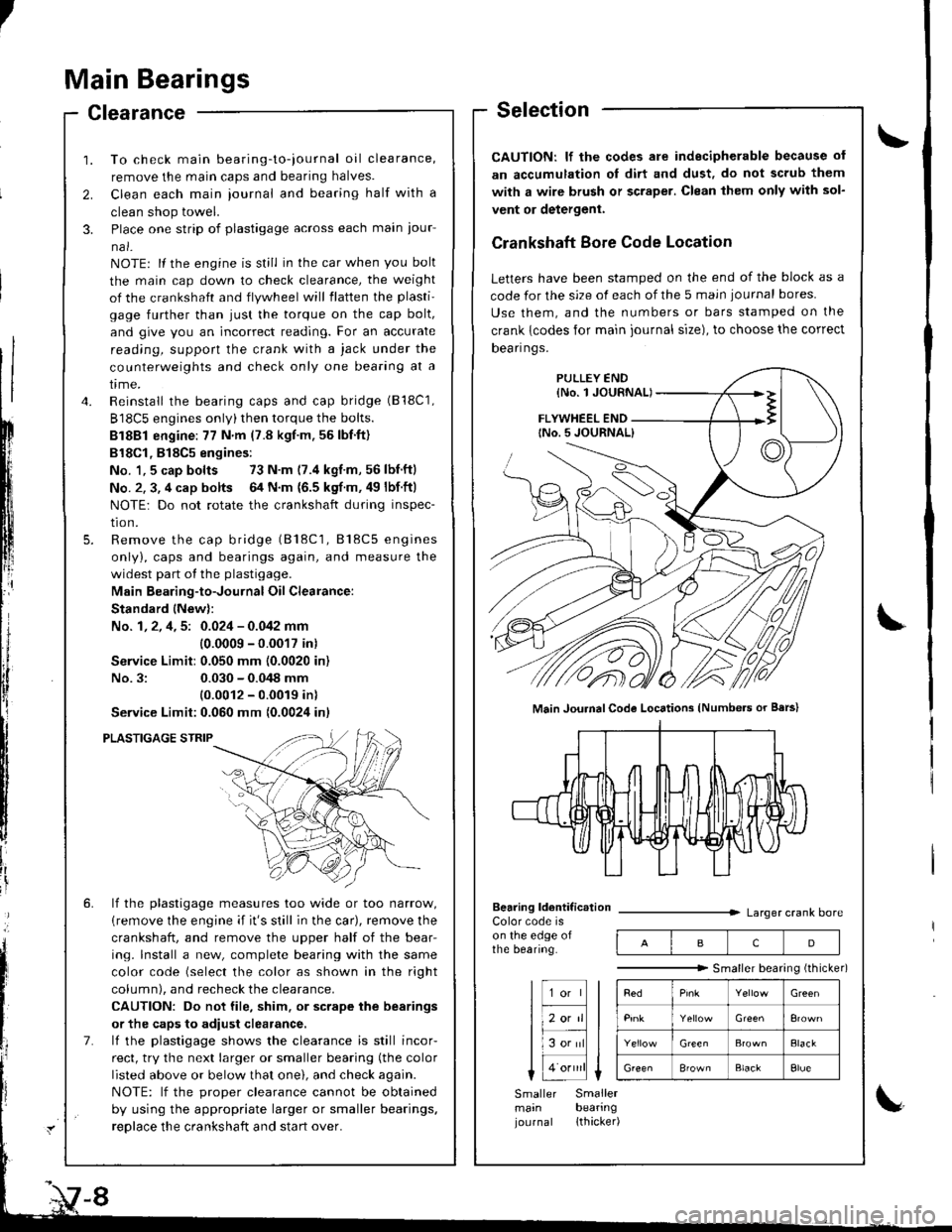
To check main bearing-to-iournal oil clearance,
remove the main caps and bearing halves.
Clean each main iournal and bearing half with a
clean shop towel.
Place one strip of plastigage across each main iour-
na l-
NOTE: lf the engine is still in the car when you bolt
the main cap down to check clearance, the weight
of the crankshaft and flywheel will flatten the plasti'
gage further than just the torque on the cap bolt,
and give you an incorrect reading. For an accurate
reading, support the crank with a jack under the
counterweights and check only one bearing at a
trme.
Reinstall the bearing caps and cap bridge (B18C1,
B18C5 engines only)then torque the bolts.
Bl8Bl engine: 77 N'm (7.8 kgt.m.56lbf.ft)
B18Cl,818C5 engines:
No. 1,5 cap bolts 73 N.m (7.4 kgf.m,56lbnftl
No. 2. 3, 4 cap bolts 64 N.m {6.5 kgf m. 49 lbf ftl
NOTE: Do not rotate the crankshaft during inspec-
tro n.
Remove the cap bridge (818C1, 818C5 engines
only), caps and bearings again, and measure the
widest part of the plastigage.
Main Bearing-to-Journal Oil Clearance:
Standard lNew):
No. 1, 2, 4, 5: 0.024 - 0.042 mm
10.0009 -0.0017 in)
Service Limit:0.050 mm (0.0020 in)
No.3:0.030 - 0.048 mm
10.0012 - 0.0019 inl
Service Limit:0.060 mm {0.0024 inl
PLASTIGAGE STRIP
lf the plastigage measures too wide or too narrow,
{remove the engine if it's still in the car), remove the
crankshaft, and remove the upper half of the bear-
ing. lnstall a new, complete bearing with the same
color code (select the color as shown in the right
column), and recheck the clearance.
CAUTION: Do not file, shim. or scrape the bearings
or the caps to adiust clearance.
lf the plastigage shows the clearance is still incor-
rect, try the next larger or smaller bearing (the color
listed above or below that one), and check again.
NOTE: lf the oroDer clearance cannot be obtained
by using the appropriate larger or smaller bearings.
reolace the crankshaft and start over.
Selection
CAUTION: lf the codes ale indecipherable because of
an accumulation oI dirt and dust, do not scrub them
with a wire bru6h or scraper. Clean lhem only with sol-
vent or detergent.
Crankshaft Bore Code Location
Letters have been stamped on the end of the block as a
code for the size of each of the 5 main iournal bores
Use them, and the numbers or bars stamped on the
crank {codes for main journal size), to choose the correct
Dean nqs,
FLYWHEEL END
Main JouhalCode Locations (Numbe.s or Bars)
Bearing ldentif ic.tionColor code ison the edge ofthe bearing.
Larger crank bore
acD
"""""""" Smallerbearingithicker)
Green
Elack
B'ownBlackElue
Smaller Smallermain bearingjournal lthacker)
Page 658 of 1681
INPUT SHAFT
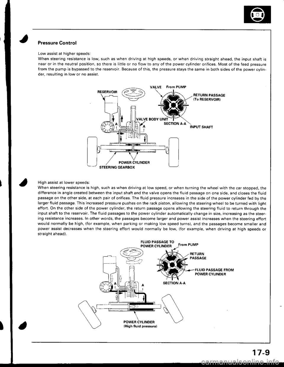
High assist at lower speedsl
When steering resistance is high, such as when driving at low speed, or when turning the wheel with the car stopped, the
diiference in angle created between the input shaft and the valve opens the tluid passage on one side, and closes the fluidpassage on the other side, at each pair of orifices. The fluid pressure lncreases in the side of the power cylinder fed by thelarger fluid passage. This increased pressure pushes on the rack piston, allowing the steering wheel to be turned with light
effon. On the other side of the power cylinder, the return passage opens allowing the steering fluid to return through theinput shaft to the reservoir. The fluid passages to the power cylinder automatically change in size, increasing as the steer-ing resistance increases. In other words, the passages become larger and power assist increases when the steering effort
would normally be high, (for example, when parking or making low speed turns), and the passages become smaller andpower assist decreases when the steering effort would normally be low, (for example, when driving at high speeds or
straight ahead).
FLUIO PASSAGE TOPOWER CYLINDER
Ce) r.r;
VK
Pressure Control
Low assist at higher speedsl
When steering resistance is low, such as when driving at high speeds, or when driving straight ahead. the lnput shaft is
near or in the neutral position, so there is liftle or no flow to any of the power cylinder orifices. Most of the feed pressure
from the pump is bypassed to the reservoir. Because of this, the pressure stays the same in both sides of the power cvlin-
der, resulting in low or no assist.
RETURN PASSAGE{To RESERVOIR)
POWER CYLINDERlHigh fluid pressurelI
ALVE FTom PUMP
RESERVOIR
SECTION A-A
17-9
Page 659 of 1681
Troubleshooting
General Troubleshooting
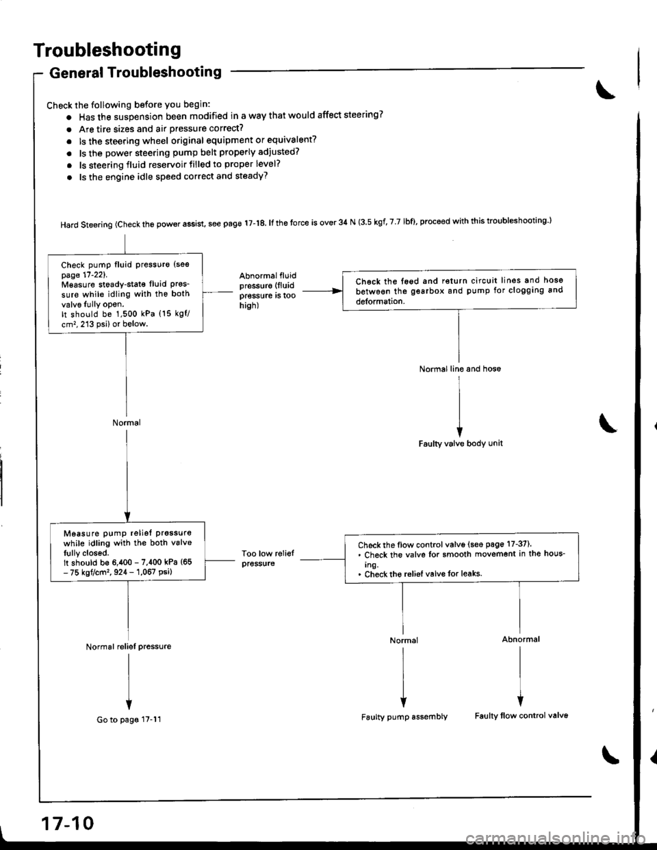
Check the following before you begin:
o Has the suspension been modified in a way that would affect steering?
. Are tire sizes and air pressure correct?
. lsthe steering wheel original equipment or equivalent?
. ls the power steering pump belt properly adiusted?
. ls steering fluid reservoirtilled to proper level?
. ls the engine idle speed correct and steadyT
Hard steering (check the power assist, see page 17-18. It the torce is over 34 N (3.5 kgf, 7 7 lbf), proceed with this troubl*hooting l
Abnormalfluidpressur€ (lluid
pressure rs roohish)
Too low reliefpress{ire
Normal line and hos6
I
II
iFaulty valve body unit
Normal Abnormal
rlrl
l{
Faulty pump assembly Faulty tlow control valv6
Ch€ck the tegd and return circuit lines and hoso
between the gearbox and pump for clogging and
detormation.
Check pump fluid Pressuro {sespage 17'221.Mgasure stoady-stat€ fluid Pres_sure while idling with the both
valv6Iully opon.It should be 1,500 kPa (15 kgf/
cm,,213 psi) or below.
Normal
Check the flow control valve (seo page 17-37).. Check the valvs Ior smooth movemont in the hous-
Ing.. Check tho reliel valvo for leaks.
Measure pump reliet prgssure
while idling with the both vslveIully closed.It should b€ 6,400 - 7,400 kPa {65- 75 kgt/cm'�, 924 - 1,067 psi)
Normal reliel pressure
I
I
+
Go to pags 17-11
17-10
Page 714 of 1681
Wheel Alignment
Caster
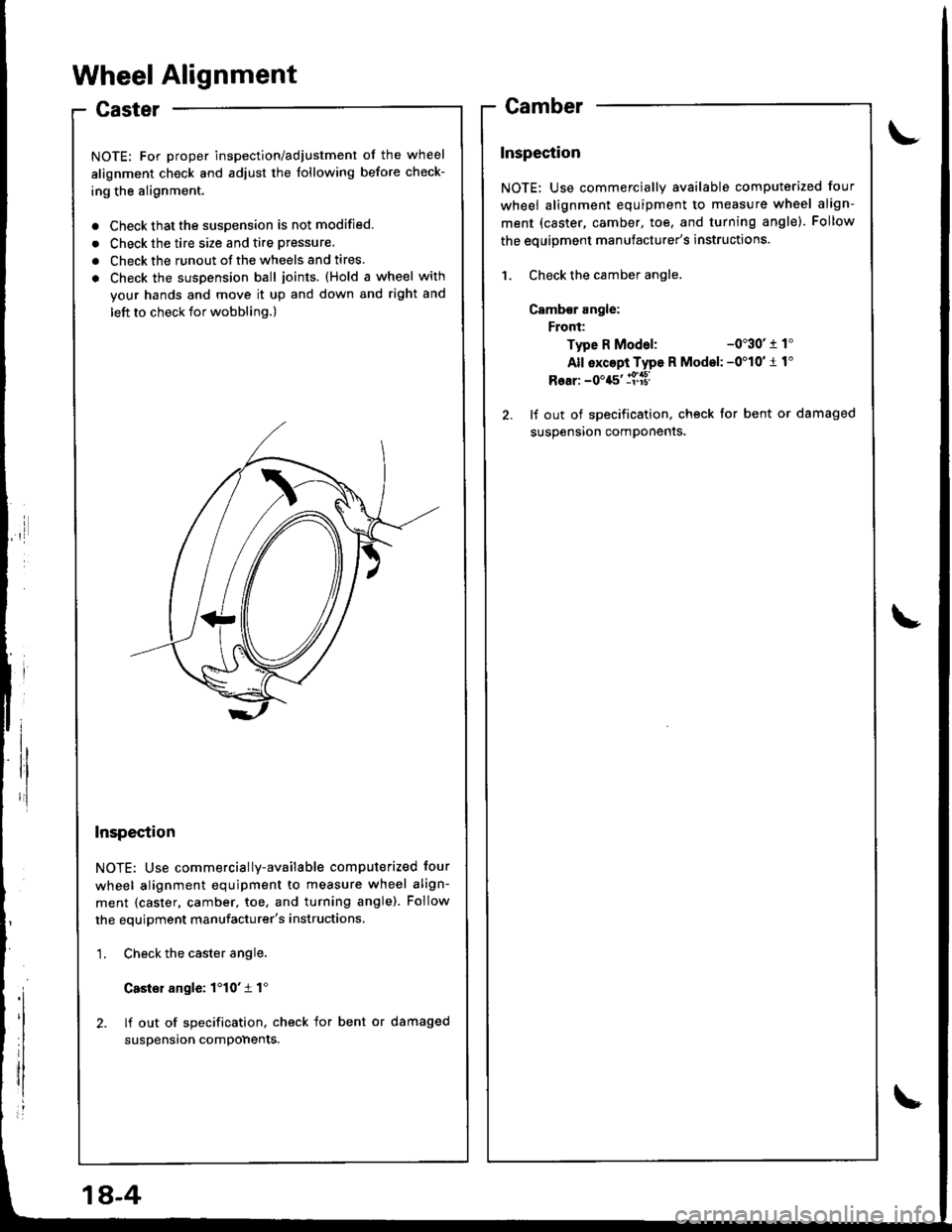
NOTE: For proper inspection/adjustment of the wheel
alignment check and adjust the following before check-
ing the alignment.
. Check that the susoension is not modified.
. Check the tire size and tire pressure.
. Check the runout of the wheels and tires.
. Check the suspension ball joints. (Hold a wheel with
your hands and move it up and down and right and
left to check tor wobbling.)
Inspection
NOTE: Use commercially-available computerized four
wheel alignment equipment to measure wheel align-
ment {caster, camber, toe, and turning angle). Follow
the equipment manufacturer's instructions.
1. Check the caster angle.
Casler angle: 1'10't 1"
2. lf out of specification. check for bent or damaged
suspension compohents.
Camber
Inspection
NOTE: Use commercially available computerized four
wheel alignment equipment to measure wheel align-
ment (caster, camber, toe, and turning angle). Follow
the eouioment manufacturer's instructions.
1. Check the camber angle.
Camb€r angle:
Front:
Type R Modal:-0"30' r 1'
All exc6pi Type R Model: -0'10'1 1"
Rear: -0'45' ll['a8l
2. lf out of specification, check for bent or damaged
susoension comDonents.
1A-4
Page 1659 of 1681
:/
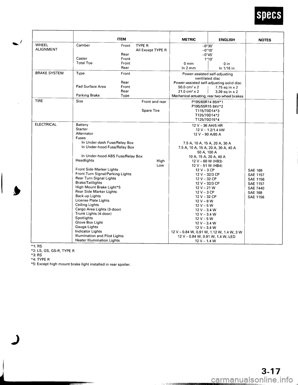
*1: RS*2: LS, GS, GS.R, TYPE R*3: RS+4: TYPE R*5: Except high mount brake light installed in rear spoirer.
ITEMMETRICENGLISHNOTES
WHEELALIGNMENTCamber Front TYPE RAll Except ryPE RRearCaster FrontTotal Toe FrontRear
-0"30'_0"10,_0"45'
1"10'omm I oinIn 2 mm I In 1/16 inBRAKE SYSTEMType Front
RearPad Surface Area FrontRearParking Brake Type
Power-assisted self-adjustingventilated discPower-assisted self-adlusting sol id disc50.0 cm2 x 2 | 7.75 sq in x 221.0 cm, x 2 | a.ZO sq in x 2Mechanical actuating, rear two wheel brakesTIRESize Front and rear
Spare Tire
P195/60R14 85H*1P195/55R15 84V*2T115t0D14*3T125/70D14*2T125n0D15*4
ELECTRICALBatteryStarterAlternatorFusesIn Under-dash Fuse/Relay BoxIn Under-hood Fuse/Relay Box
In Under-hood ABS Fuse/Relay BoxHeadlights
Front Side Marker LightsFront Turn Signal/Parking LightsRear Turn Signal LightsBrake/TaillightsHigh Mount Brake Light*5Rear Side Marker LightsBack-up LightsLicense Plate LightsCeiling LightsCargo Area Lights (3-door)Trunk Lights (4-door)SpotlightsGlove Box LightGauge LightsIndicator Lightslllumination and Pilot LightsHeater lllumination Lights
HighLow
12 V _ 36 AH/5 HR12V -1.2/'t.4kW
12V-90A/85A
7.5 A, 10 A, 15 A, 20 A, 30 A7.5 A. 10 A, 15 A, 20 A, 30 A, 40 A50A,100A10A,15A,20A,40A12V-60W(H83)12V -51 W (HB4)12V-3CP12V _3213 CP12V _32 CP12V-3213CP't2v -21 W12 V - 3 CP12V -32CP
12V_8W12V-5W12V-3.4W12V-3.4W12V_5W12V-3.4W12V-3.4W12 V - 0.84 W, 0.91 W, 1.12W, 1.4W, 3 W12 V - 0.84 W, 0.91 W, 1.4 W, LED12V-1.4W
SAE 168SAE 1157SAE 1156SAE 1157SAE 7440SAE 168SAE 1156
3-17