fuses HONDA ODYSSEY 2018 Owner's Manual (in English)
[x] Cancel search | Manufacturer: HONDA, Model Year: 2018, Model line: ODYSSEY, Model: HONDA ODYSSEY 2018Pages: 763, PDF Size: 47.02 MB
Page 4 of 763
Contents
This owner’s manual should be considered a permanent part of the
vehicle and should remain with the vehicle when it is sold.
This owner’s manual covers all models of your vehicle. You may find
descriptions of equipment and features that are not on your
particular model.
Images throughout this owner’s manu al (including the front cover)
represent features and equipment that are available on some, but
not all, models. Your particular mo del may not have some of these
features.
This owner’s manual is for vehicles sold in the United States and
Canada.
The information and specifications in cluded in this publication were
in effect at the time of approval for printing. Honda Motor Co., Ltd.
reserves the right, however, to discontinue or change specifications
or design at any time without notice and without incurring any
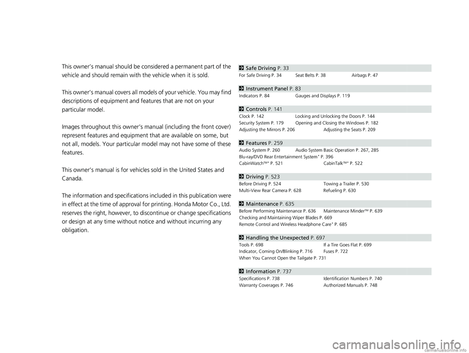
obligation.2 Safe Driving P. 33
For Safe Driving P. 34 Seat Belts P. 38 Airbags P. 47
2Instrument Panel P. 83
Indicators P. 84 Gauges and Displays P. 119
2Controls P. 141
Clock P. 142 Locking and Unlocking the Doors P. 144
Security System P. 179 Opening and Closing the Windows P. 182
Adjusting the Mirrors P. 206 Adjusting the Seats P. 209
2Features P. 259
Audio System P. 260 Audio System Basic Operation P. 267, 285
Blu-ray/DVD Rear Entertainment System* P. 396
CabinWatchTM * P. 521 CabinTalkTM* P. 522
2Driving P. 523
Before Driving P. 524 Towing a Trailer P. 530
Multi-View Rear Camera P. 628 Refueling P. 630
2 Maintenance P. 635
Before Performing Maintenance P. 636 Maintenance MinderTM P. 639
Checking and Maintaining Wiper Blades P. 669
Remote Control and Wireless Headphone Care
* P. 685
2 Handling the Unexpected P. 697
Tools P. 698 If a Tire Goes Flat P. 699
Indicator, Coming On/Blinking P. 716 Fuses P. 722
When You Cannot Open the Tailgate P. 731
2 Information P. 737
Specifications P. 738 Identification Numbers P. 740
Warranty Coverages P. 746 Authorized Manuals P. 748
18 US ODYSSEY-31THR6010.book 2 ページ 2018年12月6日 木曜日 午後4時18分
Page 696 of 763
694
Maintenance
Accessories and Modifications
Accessories
When installing accessories, check the following:
• Do not install accessories on the windshie ld. They can obstruct your view and
delay your reaction to driving conditions.
• Do not install accessories over areas marked SRS AIRBAG, on the sides or backs
of the front seats, on front or side pillars, or near the side windows.
Accessories installed in these areas may interfere with proper operation of the
vehicle’s airbags or may be propelled into you or another occupant if the airbags
deploy.
• Be sure electronic accessories do not over load electrical circuits or interfere with
proper operation of your vehicle.
2 Fuses P. 722
•Before installing any electron ic accessory, have the installer contact a dealer for
assistance. If possible, have a d ealer inspect the final installation.
1Accessories and Modifications
Honda Genuine accessor ies are recommended to
ensure proper operati on on your vehicle.
3WARNING
Improper accessories or modifications can
affect your vehicle’s handling, stability, and
performance, and cause a crash in which
you can be seriously hurt or killed.
Follow all instruction s in this owner’s
manual regarding accessories and
modifications.
18 US ODYSSEY-31THR6010.book 694 ページ 2018年12月6日 木曜日 午後4時18分
Page 699 of 763
697
Handling the Unexpected
This chapter explains how to handle unexpected troubles.
ToolsTypes of Tools .................................. 698
If a Tire Goes Flat Changing a Flat Tire ......................... 699
Engine Does Not Start Checking the Engine ........................ 708
If the Remote Battery is Weak .......... 709
Emergency Engine Stop ................... 710
Jump Starting .................................... 711
Overheating How to Handle Overheating ............. 713
Indicator, Coming On/Blinking
If the Low Oil Pressure Symbol Appears... 716
If the Charging System Indicator Comes On ................................................. 716
If the Malfunction Indicator Lamp Comes
On or Blinks ................................... 717
If the Brake System Indicator (Red) Comes On or Blinks ................................... 718
If the Brake System Indicator (Red) Comes On or Blinks at the Same Time When the Brake
System Indicator (Amber) Comes On ..... 719
If the Electric Power Steering (EPS) System Indicator Comes On ....................... 720
If the Low Tire Pressure/TPMS Indicator
Comes On or Blinks........................ 720 If the Transmission System Indicator Blinks
along with the Warning Message... 721
Fuses
Fuse Locations ................................. 722
Inspecting and Changing Fuses ........ 728
Emergency Towing ........................... 729
When You Cannot Unlock the Fuel Fill Door ................................................. 730When You Cannot Open the Tailgate..... 731When You Cannot Close the Power
Sliding Doors*................................. 733
Refueling
Refueling From a Portable Fuel Container .... 734
* Not available on all models
18 US ODYSSEY-31THR6010.book 697 ページ 2018年12月6日 木曜日 午後4時18分
Page 710 of 763
708
Handling the Unexpected
Engine Does Not Start
Checking the Engine
If the engine does not start, check the starter.
Starter conditionChecklist
Starter doesn’t turn or turns
over slowly.
The battery may be dead. Check
each of the items on the right and
respond accordingly.Check for a message on the dr iver information interface.
• If the To Start, Hold Remote Near Start Button message appears
2If the Remote Battery is Weak P. 709
uMake sure the remote is in its operating range.
2 ENGINE START/STOP Button Operating Range P. 186
Check the brightness of the interior lights.
Turn on the interior lights and check the brightness.
• If the interior lights are dim or do not come on at all
2 Battery P. 682
•If the interior lights come on normally 2 Fuses P. 722
The starter turns over normally
but the engine doesn’t start.
There may be a problem with the
fuse. Check each of the items on
the right and resp ond accordingly. Review the engine start procedure.
Follow its instructions, and try to start the engine again.
2
Starting the Engine P. 536
Check the immobilizer system indicator.
When the immobilizer system indicator is blinking, the engine cannot be started.
2Immobilizer System P. 179
Check the fuel level.
There should be enough fuel in the tank.
2 Fuel Gauge P. 119
Check the fuses.
Check all fuses, or have the vehicle checked by a dealer.
2Inspecting and Changing Fuses P. 728
If the problem continues:
2Emergency Towing P. 729
1Checking the Engine
If you must start the vehi cle immediately, use an
assisting vehicle or booster battery to jump start it.
2 Jump Starting P. 711
18 US ODYSSEY-31THR6010.book 708 ページ 2018年12月6日 木曜日 午後4時18分
Page 724 of 763
722
Handling the Unexpected
Fuses
Fuse Locations
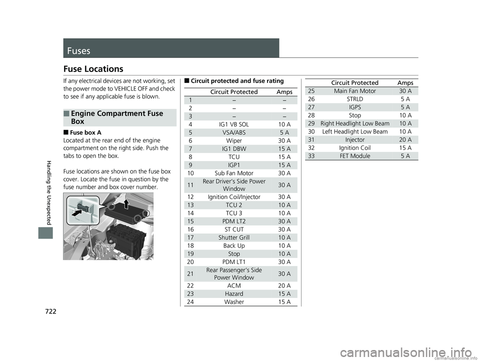
If any electrical devices are not working, set
the power mode to VEHICLE OFF and check
to see if any applic able fuse is blown.
■Fuse box A
Located at the rear end of the engine
compartment on the ri ght side. Push the
tabs to open the box.
Fuse locations are shown on the fuse box
cover. Locate the fuse in question by the
fuse number and box cover number.
■Engine Compartment Fuse
Box
■Circuit protected and fuse rating
Circuit ProtectedAmps
1−−
2− −
3−−
4 IG1 VB SOL 10 A
5VSA/ABS5 A
6 Wiper 30 A
7IG1 DBW15 A
8TCU 15A
9IGP115 A
10 Sub Fan Motor 30 A
11Rear Driver’s Side Power Window30 A
12 Ignition Coil/Injector 30 A
13TCU 210 A
14 TCU 3 10 A
15PDM LT230 A
16ST CUT 30 A
17Shutter Grill10 A
18 Back Up 10 A
19Stop10 A
20 PDM LT1 30 A
21Rear Passenger’s Side Power Window30 A
22 ACM 20 A
23Hazard15 A
24 Washer 15 A
25Main Fan Motor30 A
26 STRLD 5 A
27IGPS5 A
28 Stop 10 A
29Right Headlight Low Beam10 A
30 Left Headlight Low Beam 10 A
31Injector20 A
32 Ignition Coil 15 A
33FET Module5 A
Circuit ProtectedAmps
18 US ODYSSEY-31THR6010.book 722 ページ 2018年12月6日 木曜日 午後4時18分
Page 725 of 763
723
uuFuses uFuse Locations
Continued
Handling the Unexpected
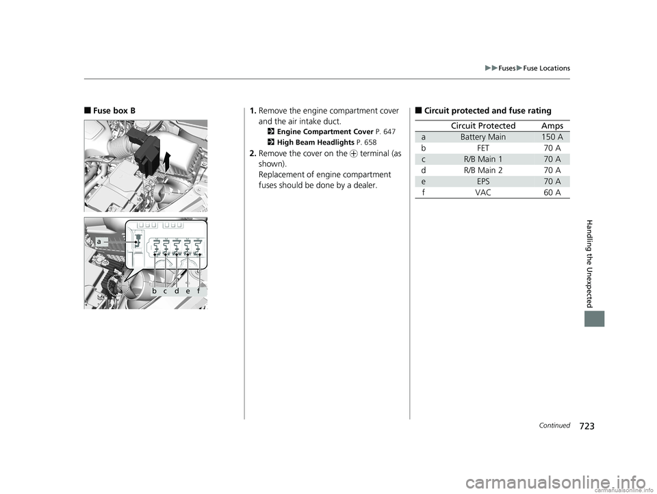
■Fuse box B
a
bcdef
1. Remove the engine compartment cover
and the air intake duct.
2 Engine Compartment Cover P. 647
2 High Beam Headlights P. 658
2.Remove the cover on the + terminal (as
shown).
Replacement of engine compartment
fuses should be done by a dealer.
■Circuit protected and fuse rating
Circuit ProtectedAmps
aBattery Main150 A
bFET70 A
cR/B Main 170 A
dR/B Main 270 A
eEPS70 A
fVAC60 A
18 US ODYSSEY-31THR6010.book 723 ページ 2018年12月6日 木曜日 午後4時18分
Page 726 of 763
724
uuFuses uFuse Locations
Handling the Unexpected
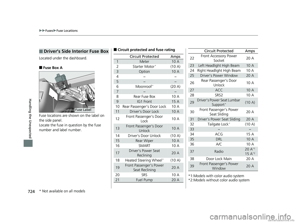
Located under the dashboard.
■Fuse Box A
Fuse locations are shown on the label on
the side panel.
Locate the fuse in question by the fuse
number and label number.
■Driver’s Side Interior Fuse Box
Fuse Label
■Circuit protected and fuse rating
Circuit ProtectedAmps
1Meter10 A
2Starter Motor*(10 A)
3Option10 A
4−−
5−−
6Moonroof*(20 A)
7−−
8Rear Fuse Box10 A
9IG1 Front15 A
10 Rear Passenger’s Door Lock 10 A
11Driver’s Door Lock10 A
12 Front Passenger’s Door
Lock 10 A
13Front Passenger’s Door
Unlock10 A
14 Driver’s Door Unlock (10 A)
15Rear Wiper10 A
16 SMART 10 A
17Driver’s Power Seat Reclining20 A
18 Heated Steering Wheel
*(10 A)
19Front Passenger’s Power Seat Reclining20 A
20 SRS 10 A
21Fuel Pump20 A*1:Models with color audio system
*2:Models without color audio system22
Front Accessory Power
Socket 20 A
23Left Headlight High Beam10 A
24 Right Headlight High Beam 10 A
25Driver’s Power Window20 A
26 Rear Passenger’s Door
Unlock 10 A
27ACC10 A
28 SRS2 10 A
29Driver’s Power Seat Lumbar Support*(10 A)
30 Front Passenger’s Power
Seat Sliding 20 A
31Driver’s Power Seat Sliding20 A
32 Tailgate Lock*(10 A)
33−−
34 ACG 15 A
35DRL10 A
36 A/C 10 A
37Radio20 A*1
15 A*2
38 Door Lock Main 20 A
39Front Passenger’s Power Window20 A
Circuit ProtectedAmps
* Not available on all models
18 US ODYSSEY-31THR6010.book 724 ページ 2018年12月6日 木曜日 午後4時18分
Page 727 of 763
725
uuFuses uFuse Locations
Continued
Handling the Unexpected
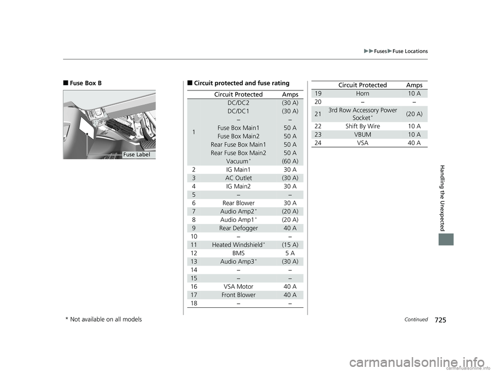
■Fuse Box B
Fuse Label
■Circuit protected and fuse rating
Circuit ProtectedAmps
1
DC/DC2(30 A)
DC/DC1(30 A)
−−
Fuse Box Main150 A
Fuse Box Main250 A
Rear Fuse Box Main150 A
Rear Fuse Box Main250 A
Vacuum*(60 A)
2 IG Main1 30 A
3AC Outlet(30 A)
4 IG Main2 30 A
5−−
6 Rear Blower 30 A
7Audio Amp2*(20 A)
8Audio Amp1*(20 A)
9Rear Defogger40 A
10 − −
11Heated Windshield*(15 A)
12 BMS 5 A
13Audio Amp3*(30 A)
14 − −
15−−
16 VSA Motor 40 A
17Front Blower40 A
18 − −
19Horn10 A
20 − −
213rd Row Accessory Power Socket*(20 A)
22 Shift By Wire 10 A
23VBUM10 A
24 VSA 40 A
Circuit ProtectedAmps
* Not available on all models
18 US ODYSSEY-31THR6010.book 725 ページ 2018年12月6日 木曜日 午後4時18分
Page 728 of 763
726
uuFuses uFuse Locations
Handling the Unexpected
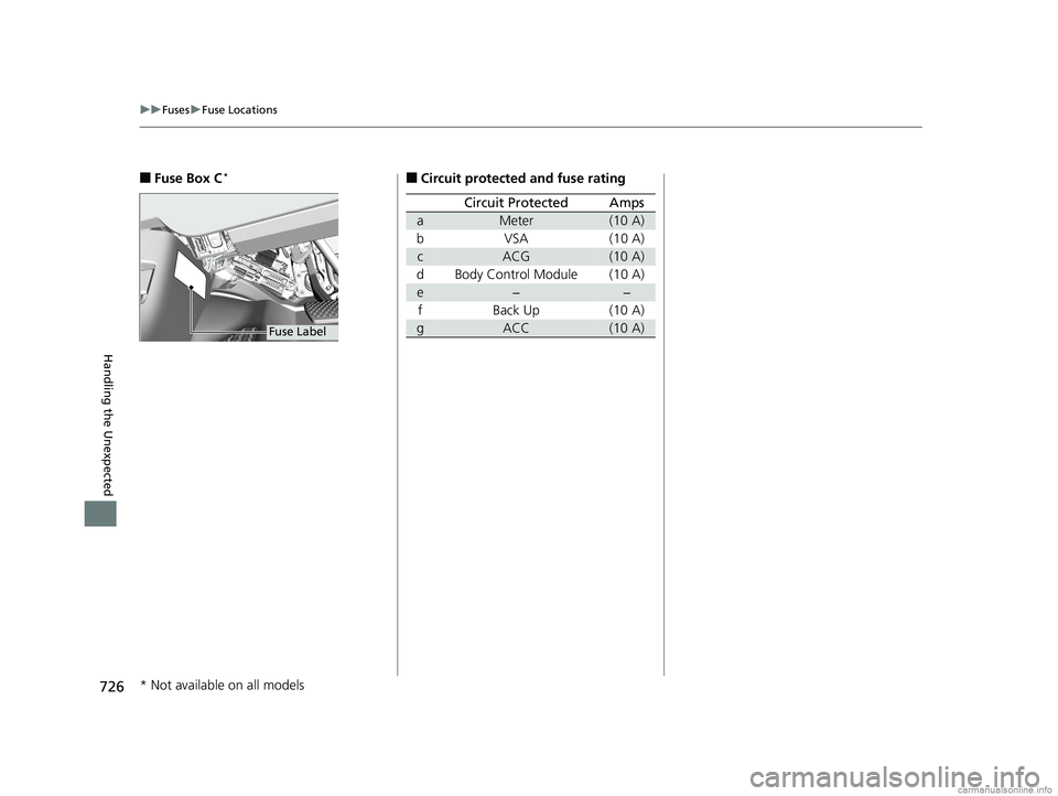
■Fuse Box C*
Fuse Label
■Circuit protected and fuse rating
Circuit ProtectedAmps
aMeter(10 A)
bVSA (10 A)
cACG(10 A)
d Body Control Module (10 A)
e−−
f Back Up (10 A)
gACC(10 A)
* Not available on all models
18 US ODYSSEY-31THR6010.book 726 ページ 2018年12月6日 木曜日 午後4時18分
Page 729 of 763
727
uuFuses uFuse Locations
Handling the Unexpected
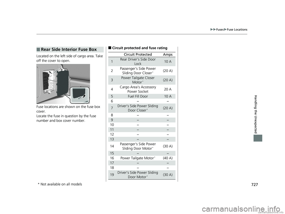
Located on the left side of cargo area. Take
off the cover to open.
Fuse locations are shown on the fuse box
cover.
Locate the fuse in question by the fuse
number and box cover number.
■Rear Side Interior Fuse Box■Circuit protected and fuse rating
Circuit ProtectedAmps
1Rear Driver’s Side Door
Lock10 A
2Passenger’s Side Power Sliding Door Closer*(20 A)
3Power Tailgate Closer Motor*(20 A)
4Cargo Area’s Accessory
Power Socket20 A
5Fuel Fill Door10 A
6−−
7Driver’s Side Power Sliding Door Closer*(20 A)
8−−
9−−
10 − −
11−−
12 − −
13−−
14 Passenger’s Side Power
Sliding Door Motor
*(30 A)
15−−
16 Power Tailgate Motor*(40 A)
17−−
18 − −
19Driver’s Side Power Sliding
Door Motor*(30 A)
* Not available on all models
18 US ODYSSEY-31THR6010.book 727 ページ 2018年12月6日 木曜日 午後4時18分