fuse HONDA RIDGELINE 2020 Owner's Manual (in English)
[x] Cancel search | Manufacturer: HONDA, Model Year: 2020, Model line: RIDGELINE, Model: HONDA RIDGELINE 2020Pages: 591, PDF Size: 32.88 MB
Page 5 of 591
Contents
Child Safety P. 55Exhaust Gas Hazard P. 70Safety Labels P. 71
Tailgate P. 127 Opening and Closing the Trunk P. 129
Moonroof* P. 139 Operating the Switches Around the Steering Wheel P. 141
Convenience Items P. 171 Climate Control System P. 187
Audio System Basic Operation P. 203 Audio Error Messages P. 272
Customized Features P. 295
Off-Highway Driving Guidelines P. 377 When Driving P. 379 Honda Sensing® P. 417
Multi-View Rear Camera P. 475 Refueling P. 477 Fuel Economy and CO
2 Emissions P. 480
Maintenance Under the Hood P. 489 Replacing Light Bulbs P. 501
Checking and Maintaining Tires P. 509 Battery P. 518 Remote Transmitter Care P. 520
Cleaning P. 522 Accessories and Modifications P. 528
Engine Does Not Start P. 543Jump Starting P. 546
Fuses P. 556 Emergency Towing P. 562
When You Cannot Unlock the Tailgate P. 564 Refueling P. 565
Devices that Emit Radio Waves P. 571 Reporting Safety Defects P. 572
Authorized Manuals P. 577 Customer Service Information P. 578
Quick Reference GuideP. 4
Safe DrivingP. 29
Instrument PanelP. 73
ControlsP. 111
FeaturesP. 195
DrivingP. 357
MaintenanceP. 481
Handling the UnexpectedP. 531
InformationP. 567
IndexP. 579
Page 8 of 591
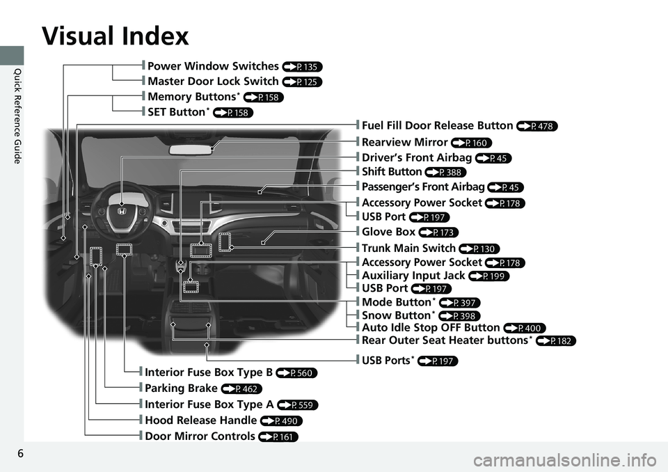
Visual Index
6
Quick Reference Guide❚Power Window Switches (P135)
❚Master Door Lock Switch (P125)
❚Memory Buttons* (P158)
❚SET Button* (P158)
❚Fuel Fill Door Release Button (P478)
❚Driver’s Front Airbag (P45)
❚Shift Button (P388)
❚Auxiliary Input Jack (P199)
❚Parking Brake (P462)
❚Interior Fuse Box Type A (P559)
❚Hood Release Handle (P490)
❚Door Mirror Controls (P161)
❚Accessory Power Socket (P178)
❚Accessory Power Socket (P178)
❚USB Port (P197)
❚Auto Idle Stop OFF Button (P400)
❚Mode Button* (P397)
❚Passenger’s Front Airbag (P45)
❚Glove Box (P173)
❚Trunk Main Switch (P130)
❚USB Port (P197)
❚USB Ports* (P197)
❚Interior Fuse Box Type B (P560)
❚Rearview Mirror (P160)
❚Snow Button* (P398)
❚Rear Outer Seat Heater buttons* (P182)
Page 26 of 591
24
Quick Reference Guide
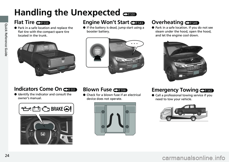
Handling the Unexpected (P531)
Flat Tire (P533)
●Park in a safe location and replace the
flat tire with the compact spare tire
located in the trunk.
Indicators Come On (P551)
●Identify the indicator and consult the
owner’s manual.
Engine Won’t Start (P543)
●If the battery is dead, jump start using a
booster battery.
Blown Fuse (P556)
●Check for a blown fuse if an electrical
device does not operate.
Overheating (P549)
●Park in a safe location. If you do not see
steam under the hood, open the hood,
and let the engine cool down.
Emergency Towing (P562)
●Call a professional towing service if you
need to tow your vehicle.
Page 371 of 591
Continued369
uuTowing a Trailer uTowing Preparation
Driving
Towing generally requires a vari ety of supplemental equipment.
To ensure the best quality, we recommend that you purchase Honda equipment
whenever possible.
Your vehicle has a class 3 trailer hitch as standard equipment. The jumper harness
and trailer brake fuse are stored in the glove box.
2 Trailer brakes P. 370
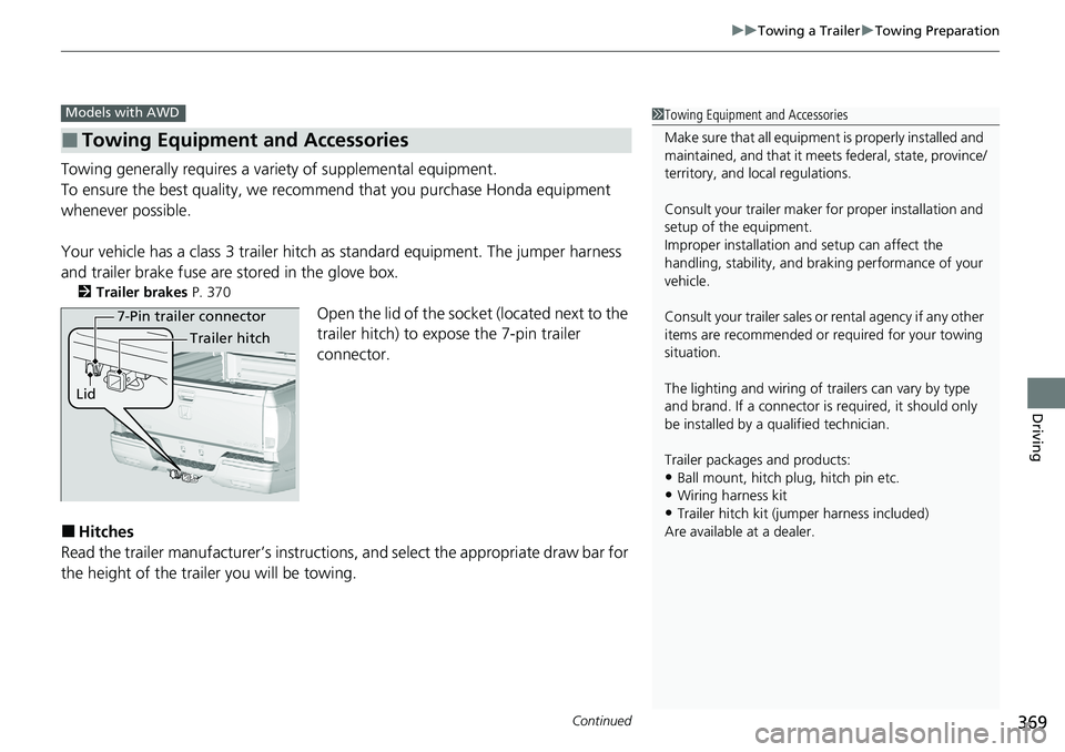
Open the lid of the socket (located next to the
trailer hitch) to expo se the 7-pin trailer
connector.
■Hitches
Read the trailer manufacturer ’s instructions, and select the appropriate draw bar for
the height of the trailer you will be towing.
■Towing Equipment and Accessories
Models with AWD1 Towing Equipment and Accessories
Make sure that all equipmen t is properly installed and
maintained, and that it meets federal, state, province/
territory, and lo cal regulations.
Consult your trai ler maker for prope r installation and
setup of the equipment.
Improper installation and setup can affect the
handling, stability, and br aking performance of your
vehicle.
Consult your traile r sales or rental agency if any other
items are recommended or required for your towing
situation.
The lighting and wiring of tra ilers can vary by type
and brand. If a connector is required, it should only
be installed by a qua lified technician.
Trailer packages and products:
•Ball mount, hitch plug, hitch pin etc.•Wiring harness kit
•Trailer hitch kit (jum per harness included)
Are available at a dealer.
7-Pin trailer connector
Lid Trailer hitch
Page 373 of 591
371
uuTowing a Trailer uTowing Preparation
Continued
Driving
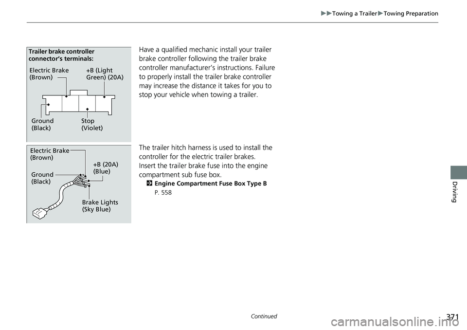
Have a qualified mechanic install your trailer
brake controller following the trailer brake
controller manufacturer’s instructions. Failure
to properly install the trailer brake controller
may increase the distance it takes for you to
stop your vehicle when towing a trailer.
The trailer hitch harness is used to install the
controller for the electric trailer brakes.
Insert the trailer brake fuse into the engine
compartment sub fuse box.
2 Engine Compartment Fuse Box Type B
P. 558
Electric Brake
(Brown)
Ground
(Black) +B (Light
Green) (20A)
Stop
(Violet)
Trailer brake controller
connector’s terminals:
Electric Brake
(Brown)
+B (20A)
(Blue)
Ground
(Black)
Brake Lights
(Sky Blue)
Page 530 of 591
528
Maintenance
Accessories and Modifications
Accessories
When installing accessories, check the following:
• Do not install accessories on the windsh ield. They can obstruct your view and
delay your reaction to driving conditions.
• Do not install any access ories over areas marked SRS AIRBAG, on the sides or
backs of the front seats, on front or si de pillars, or near the side windows.
Accessories installed in these areas may interfere with proper operation of the
vehicle’s airbags or may be propelled into you or another occupant if the airbags
deploy.
• Be sure electronic accessories do not over load electrical circuits or interfere with
proper operation of your vehicle.
2 Fuses P. 556
•Before installing any electron ic accessory, have the installer contact a dealer for
assistance. If possible, have a d ealer inspect the final installation.
• Your vehicle should not be used to carry a slide-in camper. If you install a truck
cap, be sure it is properly installed and does not exceed your vehicle’s load limits.
2Maximum Load Limit P. 361
1Accessories and Modifications
Honda Genuine accessor ies are recommended to
ensure proper operati on on your vehicle.
3WARNING
Improper accessories or modifications can
affect your vehicle’s handling, stability, and
performance, and cause a crash in which
you can be seriously hurt or killed.
Follow all instruction s in this owner’s
manual regarding accessories and
modifications.
Page 533 of 591
531
Handling the Unexpected
This chapter explains how to handle unexpected troubles.
ToolsTypes of Tools .................................. 532
If a Tire Goes Flat Changing a Flat Tire ......................... 533
Engine Does Not Start
Checking the Engine ........................ 543
If the Smart Entry Remote Battery is Weak .......................................... 544
Emergency Engine Stop ................... 545
Jump Starting .................................... 546
Overheating How to Handle Overheating ............. 549 Indicator, Coming On/Blinking
If the Low Oil Pressure Indicator Comes
On ............................................. 551
If the Charging System Indicator Comes
On ................................................. 551
If the Malfunction Indicator Lamp Comes On or Blinks ................................... 552
If the Brake System Indicator (Red) Comes On .................................................... 553
If the Electric Power Steering (EPS) System
Indicator Comes On ........................... 553
If the Low Tire Pressure/Tire Pressure Monitoring System (TPMS) Indicator Comes
On or Blinks ....................................... 554 If the Transmission System Indicator Blinks
along with the Warning Message ....... 555
Fuses
Fuse Locations ................................. 556
Inspecting and Changing Fuses ........ 561
Emergency Towing ........................... 562
When You Cannot Unlock the Fuel Fill Door ................................................. 563
When You Cannot Unlock the Tailgate .. 564
RefuelingRefueling From a Portable Fuel
Container ................................... 565
Page 545 of 591
543
Handling the Unexpected
Engine Does Not Start
Checking the Engine
If the engine does not start, check the starter.
Starter conditionChecklist
Starter doesn’t turn or turns
over slowly.
The battery may be dead. Check
each of the items on the right and
respond accordingly.Check for a message on the multi-information display.
●If the To Start, Hold Remote Near Start Button message appears
2If the Smart Entry Remote Battery is Weak P. 544
uMake sure the smart entry remote is in its operating range.
2 ENGINE START/STOP Button Operating Range P. 141
Check the brightness of the interior lights.
Turn on the interior lights and check the brightness.
●If the interior lights are dim or do not come on at all
2Battery P. 518●If the interior lights come on normally 2 Fuses P. 556
The starter turns over normally
but the engine doesn’t start.
There may be a problem with the
fuse. Check each of the items on
the right and respond accordingly. Review the engine start procedure.
Follow its instructions, and try
to start the engine again.
2 Starting the Engine P. 379
Check the immobilizer system indicator.
When the immobilizer system indicator is blinking, the engine cannot be started.
2Immobilizer System P. 132
Check the fuel level.
There should be enough fuel in the tank.
2 Fuel Gauge P. 106
Check the fuse.
Check all fuses, or have the vehicle checked by a dealer.
2Inspecting and Changing Fuses P. 561
If the problem continues:
2Emergency Towing P. 562
1Checking the Engine
If you must start the vehi cle immediately, use an
assisting vehicle or booster battery to jump start it.
2 Jump Starting P. 546
Page 558 of 591
556
Handling the Unexpected
Fuses
Fuse Locations
If any electrical devices are not working, set the power mode to VEHICLE OFF and
check to see if any app licable fuse is blown.
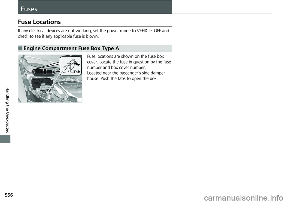
Fuse locations are shown on the fuse box
cover. Locate the fuse in question by the fuse
number and box cover number.
Located near the passenger’s side damper
house. Push the tabs to open the box.
■Engine Compartment Fuse Box Type A
Tab
Page 559 of 591
557
uuFuses uFuse Locations
Continued
Handling the Unexpected
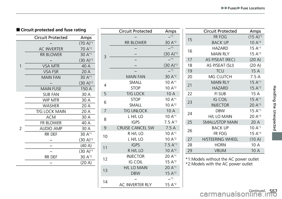
■Circuit protected and fuse rating
Circuit ProtectedAmps
1
−(70 A)*1
AC INVERTER70 A*2
RR BLOWER30 A*1
−(30 A)*2
VSA MTR40 A
VSA FSR20 A
MAIN FAN30 A*1
−(30 A)*2
MAIN FUSE150 A
2
SUB FAN30 A
WIP MTR30 A
WASHER20 A
T/G LOCK MAIN20 A
ACM30 A
FR BLOWER40 A
AUDIO AMP30 A
RR DEF30 A*1
−(30 A)*2
−(40 A)
−(30 A)*1
RR DEF30 A*2
−(20 A)
3
−−*1
RR BLOWER30 A*2
−−*1
−(30 A)*2
−−*1
−(30 A)*2
−−*1
MAIN FAN30 A*2
4SMALL 10 A*1
STOP
10 A*2
5T/G LOCK10 A
6 STOP 10 A*1
SMALL
10 A*2
7T/G UNLOCK10 A
8 L H/L LO 10 A*1
IGPS
7.5 A*2
9CRUISE CANCEL SW7.5 A
10 R H/L LO 10 A*1
L H/L LO
10 A*2
11IGPS7.5 A*1
R H/L LO10 A*2
12INJECTOR 20 A*1
IG COIL
15 A*2
13H/L LO MAIN20 A*1
DBW15 A*2
14−−*1
AC INVERTER RLY 15 A*2
Circuit ProtectedAmps
*1:Models without the AC power outlet
*2:Models with the AC power outlet
15FR FOG(15 A)*1
BACK UP10 A*2
16HAZARD 15 A*1
MAIN RLY 15 A*2
17AS P/SEAT (REC)(20 A)
18 AS P/SEAT (SLI) (20 A)
19TCU15 A
20 MG CLUTCH 7.5 A
21MAIN RLY15 A*1
HAZARD15 A*2
22 FI SUB 15 A
23IG COIL15 A*1
INJECTOR20 A*2
24DBW 15 A*1
H/L LO MAIN 20 A*2
25SMALL/STOP MAIN20 A
26 BACK UP 10 A*1
FR FOG
15 A*2
27H/STEERING WHEEL(10 A)
28 HORN 10 A
29VBUM10 A
Circuit ProtectedAmps