fuse box HONDA RIDGELINE 2022 Owners Manual
[x] Cancel search | Manufacturer: HONDA, Model Year: 2022, Model line: RIDGELINE, Model: HONDA RIDGELINE 2022Pages: 598, PDF Size: 12.42 MB
Page 10 of 598
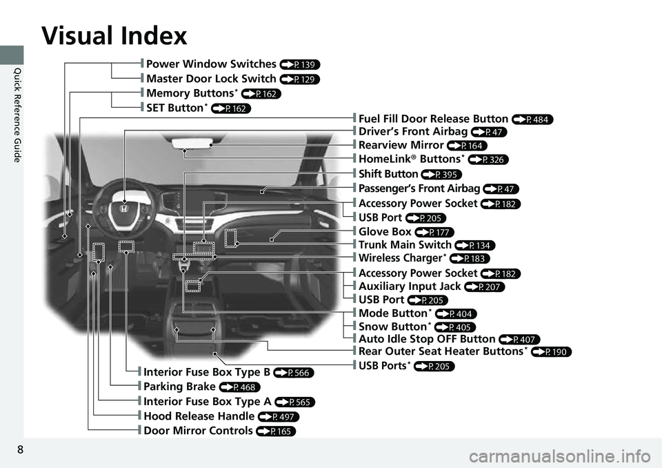
Visual Index
8
Quick Reference Guide❚Power Window Switches (P139)
❚Master Door Lock Switch (P129)
❚Memory Buttons* (P162)
❚SET Button* (P162)❚Fuel Fill Door Release Button (P484)
❚Driver’s Front Airbag (P47)
❚Shift Button (P395)
❚Auxiliary Input Jack (P207)
❚Parking Brake (P468)
❚Interior Fuse Box Type A (P565)
❚Hood Release Handle (P497)
❚Door Mirror Controls (P165)
❚Accessory Power Socket (P182)
❚USB Port (P205)
❚Auto Idle Stop OFF Button (P407)
❚Mode Button* (P404)
❚Trunk Main Switch (P134)
❚Interior Fuse Box Type B (P566)
❚Snow Button* (P405)
❚Wireless Charger* (P183)
❚Glove Box (P177)
❚USB Ports* (P205)
❚Accessory Power Socket (P182)
❚Passenger’s Front Airbag (P47)
❚Rearview Mirror (P164)
❚HomeLink® Buttons* (P326)
❚Rear Outer Seat Heater Buttons* (P190)
❚USB Port (P205)
Page 377 of 598
Continued375
uuTowing a Trailer uTowing Preparation
Driving
Towing generally requires a vari ety of supplemental equipment.
To ensure the best quality, we recommend that you purchase Honda equipment
whenever possible.
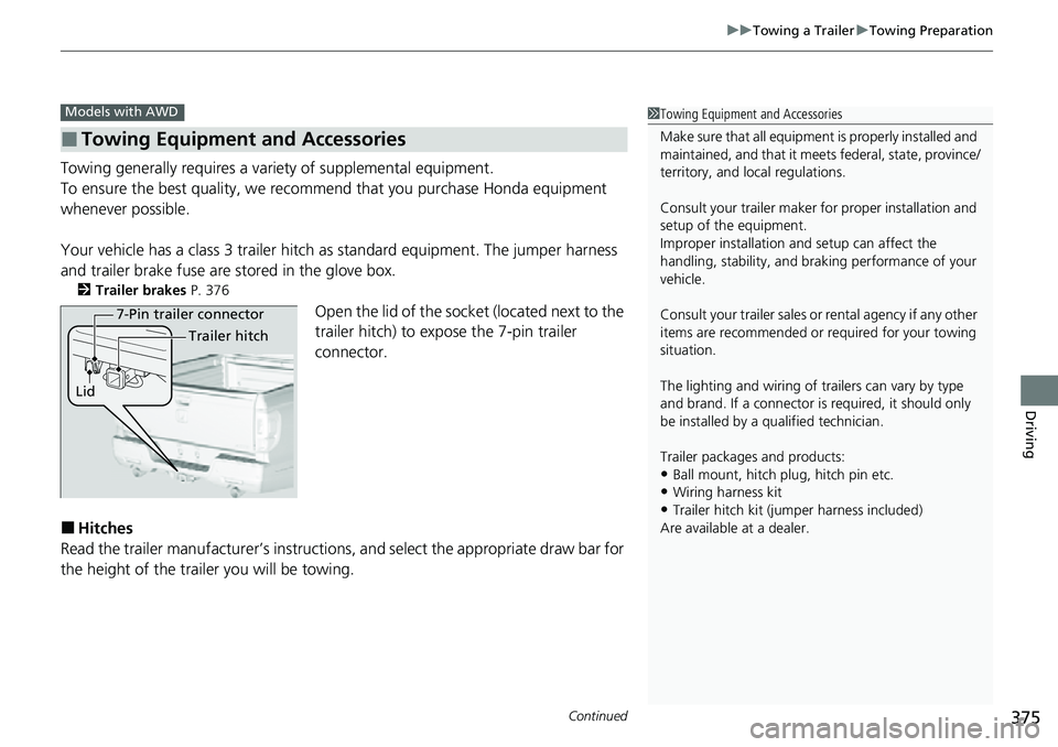
Your vehicle has a class 3 trailer hitch as standard equipment. The jumper harness
and trailer brake fuse are stored in the glove box.
2 Trailer brakes P. 376
Open the lid of the socket (located next to the
trailer hitch) to expo se the 7-pin trailer
connector.
■Hitches
Read the trailer manufacturer ’s instructions, and select the appropriate draw bar for
the height of the trailer you will be towing.
■Towing Equipment and Accessories
Models with AWD1 Towing Equipment and Accessories
Make sure that all equipmen t is properly installed and
maintained, and that it meets federal, state, province/
territory, and lo cal regulations.
Consult your trai ler maker for prope r installation and
setup of the equipment.
Improper installation and setup can affect the
handling, stability, and br aking performance of your
vehicle.
Consult your traile r sales or rental agency if any other
items are recommended or required for your towing
situation.
The lighting and wiring of tra ilers can vary by type
and brand. If a connector is required, it should only
be installed by a qua lified technician.
Trailer packages and products:
•Ball mount, hitch plug, hitch pin etc.•Wiring harness kit
•Trailer hitch kit (jum per harness included)
Are available at a dealer.
7-Pin trailer connector
Lid Trailer hitch
Page 379 of 598
377
uuTowing a Trailer uTowing Preparation
Continued
Driving
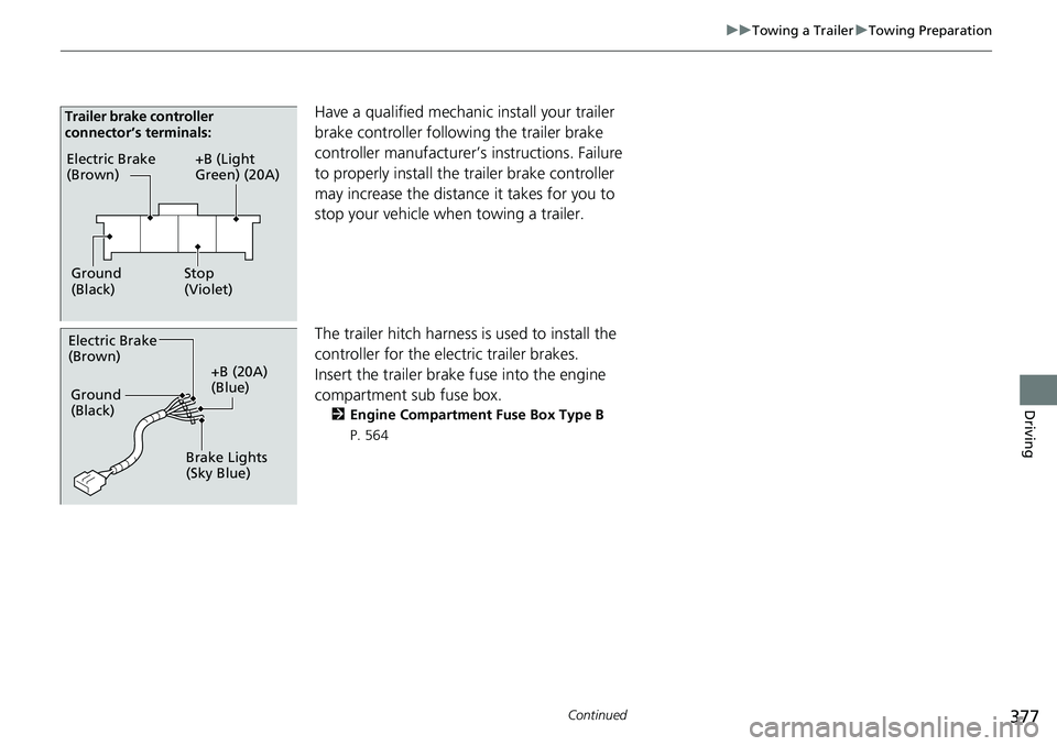
Have a qualified mechanic install your trailer
brake controller following the trailer brake
controller manufacturer’s instructions. Failure
to properly install the trailer brake controller
may increase the distance it takes for you to
stop your vehicle when towing a trailer.
The trailer hitch harness is used to install the
controller for the electric trailer brakes.
Insert the trailer brake fuse into the engine
compartment sub fuse box.
2 Engine Compartment Fuse Box Type B
P. 564
Electric Brake
(Brown)
Ground
(Black) +B (Light
Green) (20A)
Stop
(Violet)
Trailer brake controller
connector’s terminals:
Electric Brake
(Brown)
+B (20A)
(Blue)
Ground
(Black)
Brake Lights
(Sky Blue)
Page 564 of 598
562
Handling the Unexpected
Fuses
Fuse Locations
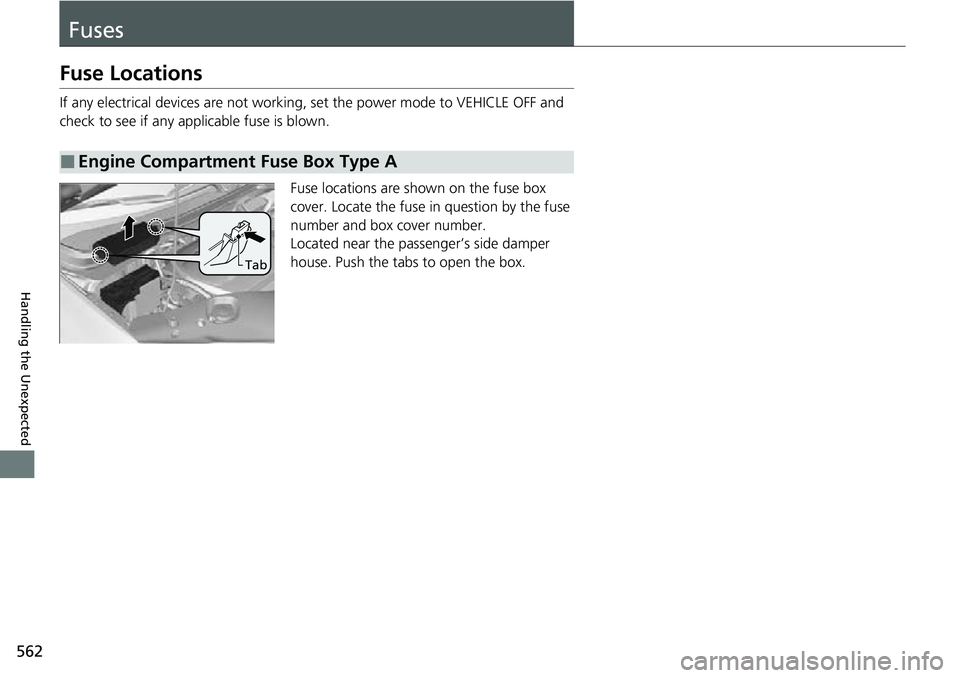
If any electrical devices are not working, set the power mode to VEHICLE OFF and
check to see if any app licable fuse is blown.
Fuse locations are shown on the fuse box
cover. Locate the fuse in question by the fuse
number and box cover number.
Located near the passenger’s side damper
house. Push the tabs to open the box.
■Engine Compartment Fuse Box Type A
Tab
Page 566 of 598
564
uuFuses uFuse Locations
Handling the Unexpected
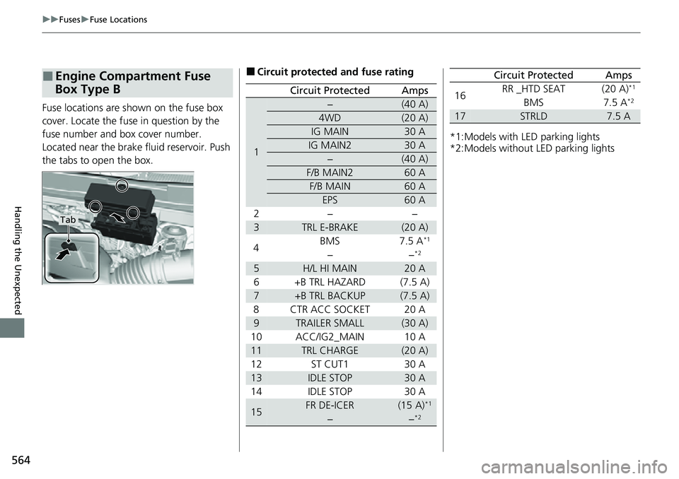
Fuse locations are shown on the fuse box
cover. Locate the fuse in question by the
fuse number and box cover number.
Located near the brake fluid reservoir. Push
the tabs to open the box.
■Engine Compartment Fuse
Box Type B
Tab
■Circuit protected and fuse rating
Circuit ProtectedAmps
1
−(40 A)
4WD(20 A)
IG MAIN30 A
IG MAIN230 A
−(40 A)
F/B MAIN260 A
F/B MAIN60 A
EPS60 A
2−−
3TRL E-BRAKE(20 A)
4 BMS
7.5 A*1
−−*2
5H/L HI MAIN20 A
6 +B TRL HAZARD (7.5 A)
7+B TRL BACKUP(7.5 A)
8 CTR ACC SOCKET 20 A
9TRAILER SMALL(30 A)
10 ACC/IG2_MAIN 10 A
11TRL CHARGE(20 A)
12ST CUT130 A
13IDLE STOP30 A
14IDLE STOP30 A
15FR DE-ICER(15 A)*1
−−*2
*1:Models with LED parking lights
*2:Models without LED parking lights
16RR _HTD SEAT(20 A)*1
BMS7.5 A*2
17STRLD7.5 A
Circuit ProtectedAmps
Page 567 of 598
565
uuFuses uFuse Locations
Continued
Handling the Unexpected
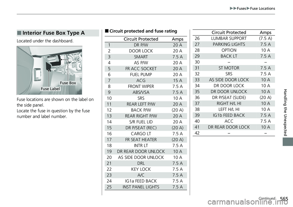
Located under the dashboard.
Fuse locations are shown on the label on
the side panel.
Locate the fuse in question by the fuse
number and label number.
■Interior Fuse Box Type A
Fuse Box
Fuse Label
■Circuit protected and fuse rating
Circuit ProtectedAmps
1DR P/W20 A
2DOOR LOCK20 A
3SMART7.5 A
4AS P/W20 A
5FR ACC SOCKET20 A
6FUEL PUMP20 A
7ACG15 A
8FRONT WIPER7.5 A
9ABS/VSA7.5 A
10SRS10 A
11REAR LEFT P/W20 A
12BACK P/W(20 A)
13REAR RIGHT P/W20 A
14S/R FUEL LID20 A
15DR P/SEAT (REC)(20 A)
16CARGO LT7.5 A
17FR SEAT HEATER(20 A)
18INTR LT7.5 A
19DR REAR DOOR UNLOCK10 A
20AS SIDE DOOR UNLOCK10 A
21DRL7.5 A
22KEY LOCK7.5 A
23A/C7.5 A
24IG1a FEED BACK7.5 A
25INST PANEL LIGHTS7.5 A
26LUMBAR SUPPORT(7.5 A)
27PARKING LIGHTS7.5 A
28OPTION10 A
29BACK LT7.5 A
30−−
31ST MOTOR7.5 A
32SRS7.5 A
33AS SIDE DOOR LOCK10 A
34DR DOOR LOCK10 A
35DR DOOR UNLOCK10 A
36DR P/SEAT (SLIDE)(20 A)
37RIGHT H/L HI10 A
38LEFT H/L HI10 A
39IG1b FEED BACK7.5 A
40ACC7.5 A
41DR REAR DOOR LOCK10 A
42−−
Circuit ProtectedAmps
Page 568 of 598
566
uuFuses uFuse Locations
Handling the Unexpected
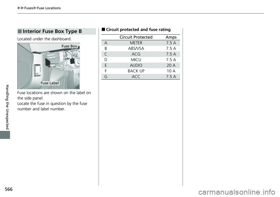
Located under the dashboard.
Fuse locations are shown on the label on
the side panel.
Locate the fuse in question by the fuse
number and label number.
■Interior Fuse Box Type B
Fuse Box
Fuse Label
■Circuit protected and fuse rating
Circuit ProtectedAmps
AMETER7.5 A
BABS/VSA7.5 A
CACG7.5 A
DMICU7.5 A
EAUDIO20 A
FBACK UP10 A
GACC7.5 A
Page 569 of 598
567
uuFuses uInspecting and Changing Fuses
Handling the Unexpected
Inspecting and Changing Fuses
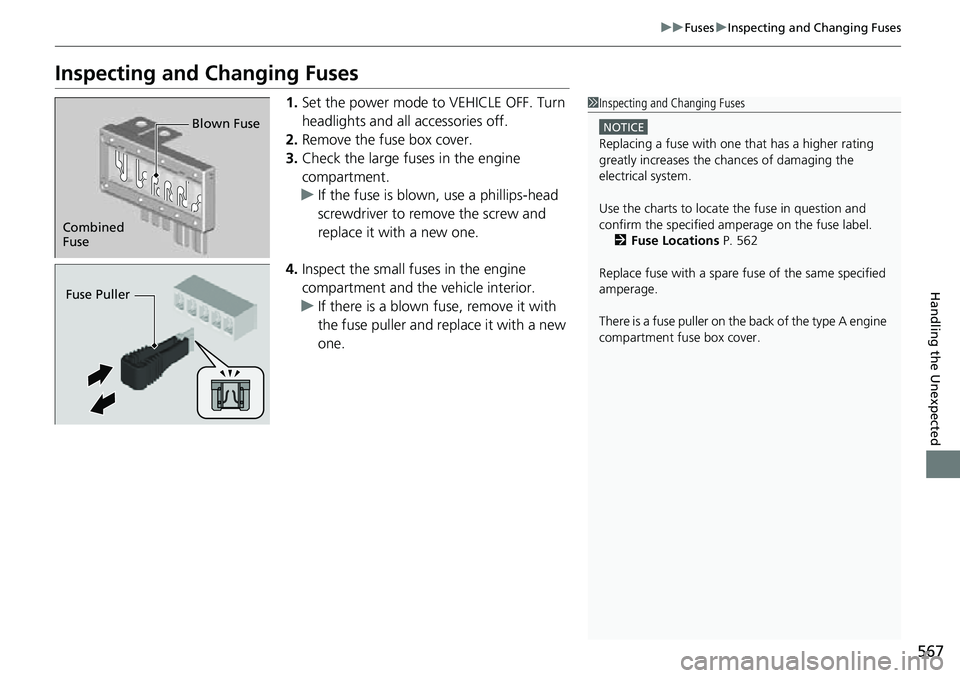
1. Set the power mode to VEHICLE OFF. Turn
headlights and all accessories off.
2. Remove the fuse box cover.
3. Check the large fuses in the engine
compartment.
u If the fuse is blown, use a phillips-head
screwdriver to remove the screw and
replace it with a new one.
4. Inspect the small fu ses in the engine
compartment and the vehicle interior.
u If there is a blown fuse, remove it with
the fuse puller and replace it with a new
one.1Inspecting and Changing Fuses
NOTICE
Replacing a fuse with on e that has a higher rating
greatly increases the chances of damaging the
electrical system.
Use the charts to locate the fuse in question and
confirm the specified amperage on the fuse labelM 2 Fuse Locations P. 562
Replace fuse with a spare fuse of the same specified
amperage.
There is a fuse puller on the back of the type A engine
compartment fuse box cover.
Combined
Fuse Blown Fuse
Fuse Puller
Page 592 of 598
590
Index
Engine Coolant ........................................ 504
Windshield Washer .................................. 507
FM/AM Radio ............................................ 236
Fog Lights .................................................. 152
Indicator .................................................... 86
Folding Up the Rear Seat ......................... 169
Foot Brake ................................................. 469
Front Airbags (SRS) ..................................... 47
Front Seats ................................................ 166
Adjusting ................................................. 166
Front Sensor Camera ................................ 465
Fuel ...................................................... 23, 483
Economy ................................................. 486
Gauge ..................................................... 110
Instant Fuel Economy ............................... 114
Low Fuel Indicator ..................................... 82
Range ...................................................... 114
Recommendation .................................... 483
Refueling ................................................. 483
Fuel Economy and CO
2 Emissions ............ 486
Fuel Fill Door ....................................... 23, 484
Unable to Unlock ..................................... 569
Fuses .......................................................... 562
Inspecting and Changing ......................... 567
Locations ......................... 562, 564, 565, 566
G
Gasoline (Fuel) Economy ................................................. 486
Gauge ..................................................... 110 Information ............................................. 483
Instant Fuel Economy .............................. 114
Low Fuel Indicator ..................................... 82
Refueling................................................. 483
Gauges ...................................................... 110
Glass (care) ................................................ 533
Glove Box .................................................. 177
H
Halogen Bulbs .......................................... 508
Handling the Unexpected ........................ 537
HandsFreeLink ® (HFL) ............................... 329
Automatic Import of Ce llular Phonebook and
Call History ............................................ 342
Displaying Messages................................ 356
HFL Buttons............................................. 329
HFL Menus .............................................. 332
HFL Status Display ................................... 331
In Case of Emergency .............................. 360
Limitations for Manual Operation ............ 331
Making a Call .......................................... 350
Options During a Call .............................. 353
Phone Setup............................................ 337
Phonebook Phonetic Modification ........... 346
Receiving a Call ....................................... 353
Receiving a Text/E-mail Message.............. 354
Ring Tone................................................ 341
Selecting a Text/E-mail Message Account ................................................ 355
Speed Dial ............................................... 343 To Set Up Text Message/E-mail
Options ................................................. 340
Hazard Warning Button .............................. 6
Hazard Warning Indicator ......................... 85
HD Radio
TM............................................... 238
Head Restraints ................................ 171, 172
Headlights ................................................ 149
Aiming.................................................... 508
Auto High-Beam System ......................... 154
Automatic Operation .............................. 150
Dimming......................................... 149, 153
Operating ............................................... 149
Heated Door Mirrors ............................... 159
Heated Steering Wheel ........................... 187
Heated Windshield Button ...................... 159
Heater (Steering Wheel) .......................... 187
Heaters (Seat) ........................... 188, 189, 190
HFL (HandsFreeLink ®) .............................. 329
High Beam Indicator .................................. 85
Hill Start Assist System ............................. 391
HomeLink ® Universal Transceiver ........... 323
Honda App License Agreement .............. 283
Honda Sensing ®................................ 24, 423
HondaLink ®............................................ 261
I
Identification Numbers ............................ 576
Engine and Transmission ......................... 576
Vehicle Identification............................... 576