HUMMER H3 2006 Owners Manual
Manufacturer: HUMMER, Model Year: 2006, Model line: H3, Model: HUMMER H3 2006Pages: 410, PDF Size: 2.61 MB
Page 111 of 410
Universal Home Remote System
Operation
Do not use the Universal Home Remote with any
garage door opener that does not have the “stop and
reverse” feature. This includes any garage door opener
model manufactured before April 1, 1982. If you
have a newer garage door opener with rolling codes,
please be sure to follow Steps 6 through 8 to complete
the programming of your Universal Home Remote
Transmitter.
Read the instructions completely before attempting to
program the Universal Home Remote. Because of
the steps involved, it may be helpful to have another
person available to assist you in the programming steps.
Keep the original hand-held transmitter for use in
other vehicles as well as for future Universal Home
Remote programming. It is also recommended that upon
the sale of the vehicle, the programmed Universal
Home Remote buttons should be erased for security
purposes. See “Erasing Universal Home Remote
Buttons” later in this section or, for assistance, see
Customer Assistance Offices on page 7-4.Be sure that people and objects are clear of the garage
door or gate operator you are programming. When
programming a garage door, it is advised to park outside
of the garage.
It is recommended that a new battery be installed in
your hand-held transmitter for quicker and more
accurate transmission of the radio-frequency signal.
Programming Universal Home Remote
Your vehicle’s engine should be turned off while
programming Universal Home Remote. Follow these
steps to program up to three channels:
1. Press and hold down the two outside Universal
Home Remote buttons, releasing only when the
Universal Home Remote indicator light begins
to �ash, after 20 seconds. Do not hold down the
buttons for longer than 30 seconds and do not
repeat this step to program a second and/or third
hand-held transmitter to the remaining two Universal
Home Remote buttons.
2. Position the end of your hand-held transmitter
about 1 to 3 inches (3 to 8 cm) away from the
Universal Home Remote buttons while keeping the
indicator light in view.
2-39
Page 112 of 410

3. Simultaneously press and hold both the desired
Universal Home Remote button and the hand-held
transmitter button. Do not release the buttons
until Step 4 has been completed.
Some entry gates and garage door openers may
require you to substitute Step 3 with the procedure
noted in “Gate Operator and Canadian
Programming” later in this section.
4. The indicator light will �ash slowly at �rst and then
rapidly after Universal Home Remote successfully
receives the frequency signal from the hand-held
transmitter. Release both buttons.
5. Press and hold the newly-trained Universal Home
Remote button and observe the indicator light.
If the indicator light stays on constantly,
programming is complete and your device should
activate when the Universal Home Remote button is
pressed and released.
To program the remaining two Universal Home
Remote buttons, begin with Step 2 under
“Programming Universal Home Remote.” Do not
repeat Step 1 as this will erase all of the
programmed channels.
If the indicator light blinks rapidly for two seconds
and then turns to a constant light, continue with
Steps 6 through 8 following to complete the
programming of a rolling-code equipped device,
most commonly, a garage door opener.6. Locate in the garage, the garage door opener
receiver (motor-head unit). Locate the “Learn”
or “Smart” button. This can usually be found where
the hanging antenna wire is attached to the
motor-head unit.
7. Firmly press and release the “Learn” or “Smart”
button. The name and color of the button may
vary by manufacturer.
You will have 30 seconds to start Step 8.
8. Return to the vehicle. Firmly press and hold the
programmed Universal Home Remote button for
two seconds, then release. Repeat the
press/hold/release sequence a second time, and
depending on the brand of the garage door opener,
or other rolling code device, repeat this sequence
a third time to complete the programming.
The Universal Home Remote should now activate
your rolling-code equipped device.
To program the remaining two Universal Home Remote
buttons, begin with Step 2 of “Programming Universal
Home Remote.” You do not want to repeat Step 1,
as this will erase all previous programming from
the Universal Home Remote buttons.
2-40
Page 113 of 410
Gate Operator and Canadian
Programming
Canadian radio-frequency laws require transmitter
signals to time out or quit after several seconds of
transmission. This may not be long enough for Universal
Home Remote to pick up the signal during programming.
Similarly, some U.S. gate operators are manufactured
to time out in the same manner.
If you live in Canada, or you are having difficulty
programming a gate operator or garage door opener by
using the “Programming Universal Home Remote”
procedures, regardless of where you live, replace
Step 3 under “Programming Universal Home Remote”
with the following:
Continue to press and hold the Universal Home Remote
button while you press and release every two seconds
(cycle) the hand-held transmitter button until the
frequency signal has been successfully accepted by the
Universal Home Remote. The Universal Home Remote
indicator light will �ash slowly at �rst and then rapidly.
Proceed with Step 4 under “Programming Universal
Home Remote” to complete.
Using Universal Home Remote
Press and hold the appropriate Universal Home Remote
button for at least half of a second. The indicator light
will come on while the signal is being transmitted.
Erasing Universal Home
Remote Buttons
To erase programming from the three Universal Home
Remote buttons do the following:
1. Press and hold down the two outside buttons until
the indicator light begins to �ash, after 20 seconds.
Do not hold the two outside buttons for longer
than 30 seconds.
2. Release both buttons.
The Universal Home Remote is now in the train
(learning) mode and can be programmed at any time
beginning with Step 2 under “Programming Universal
Home Remote” shown earlier in this section.
Individual buttons cannot be erased, but they can be
reprogrammed. See “Reprogramming a Single Universal
Home Remote Button” following this section.
2-41
Page 114 of 410
Reprogramming a Single Universal
Home Remote Button
To program a device to Universal Home Remote using
a Universal Home Remote button previously trained,
follow these steps:
1. Press and hold the desired Universal Home
Remote button. Do not release the button.
2. The indicator light will begin to �ash after
20 seconds. While still holding the Universal Home
Remote button, proceed with Step 2 under
“Programming Universal Home Remote” shown
earlier in this section.
For additional information on Universal Home Remote,
seeCustomer Assistance Offices on page 7-4.
Storage Areas
Glove Box
Open the glove box by pulling the bottom of the handle
upward.
Cupholder(s)
Your vehicle may have two cupholders in front of the
front armrest storage area. You may also have a
cupholder in the center of the rear bench seat. Pull
down on the lid to open the cupholder.
Front Seat Storage Net
Your vehicle is equipped with storage nets located on
the back of the front seats. To remove these nets,
pull out on each of the four clips located on the net.
2-42
Page 115 of 410
Front Armrest Storage Area
Your vehicle is equipped with a front armrest storage
area. To open, lift the latch on the front of the armrest
and pull up.
Luggage Carrier
If your vehicle has this feature, you can load cargo on
your vehicle.
The luggage carrier consists of siderails attached to the
roof. The crossrails attach into the siderails and can
be moved back and forth to accommodate various
cargo sizes.
Notice:Loading cargo on the luggage carrier that
weighs more than 250 lbs. (113 kg) or hangs
over the rear or sides of the vehicle may damage
your vehicle. Load cargo only on top of the
crossrails and tie the cargo down to the crossrail
support cargo tie-down loops, making sure to fasten
it securely
Do not exceed the maximum vehicle capacity when
loading your vehicle. For more information on vehicle
capacity and loading, seeLoading Your Vehicle on
page 4-52.
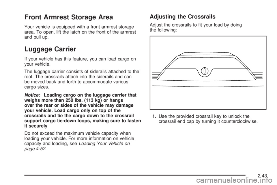
Adjusting the Crossrails
Adjust the crossrails to �t your load by doing
the following:
1. Use the provided crossrail key to unlock the
crossrail end cap by turning it counterclockwise.
2-43
Page 116 of 410
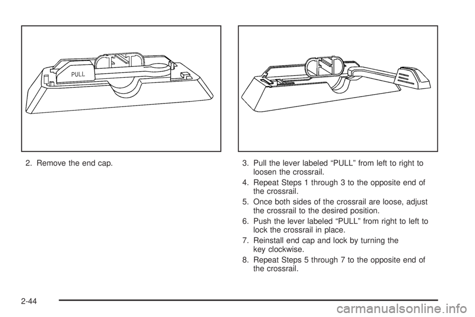
2. Remove the end cap. 3. Pull the lever labeled “PULL” from left to right to
loosen the crossrail.
4. Repeat Steps 1 through 3 to the opposite end of
the crossrail.
5. Once both sides of the crossrail are loose, adjust
the crossrail to the desired position.
6. Push the lever labeled “PULL” from right to left to
lock the crossrail in place.
7. Reinstall end cap and lock by turning the
key clockwise.
8. Repeat Steps 5 through 7 to the opposite end of
the crossrail.
2-44
Page 117 of 410

Stop Tabs
If your vehicle has a sunroof, it will have a crossrail stop
tab placed in the siderail. This tab prevents you from
moving the crossrails past the opening of the sunroof
and loading cargo too far forward.
Once you load the cargo onto the crossrails, secure it
by tying it down to the cargo tie downs. Do not load
cargo directly on the roof of your vehicle. SeeCargo Tie
Downs on page 2-45for more information.
Rear Storage Area
Your vehicle is equipped with a rear storage area
located on the passenger’s side of the cargo area.
To open, pull the two tabs out and open lid.
Convenience Net
Your vehicle may be equipped with a convenience net
in the rear of the vehicle. Put small loads behind the net.
The net is not for heavier loads. Store them as far
forward as you can.
Cargo Cover
Notice:If you put items onto the cargo cover, the
weight of the items could cause the attachment clips
to break. You would no longer be able to attach
and use the cargo cover. The repairs would not be
covered by your warranty. Never put anything
on top of the cargo cover.
If your vehicle has a cargo cover, you can use it to
cover items in the rear of the vehicle. Remove the cover
from its pouch and place the loops found on each
corner of the cover, over the two pegs in each corner of
the rear if the vehicle. When it is not in use, fold up
the cover and return it to the pouch.
Cargo Tie Downs
Your vehicle is equipped with four cargo tie-downs.
These tie-downs are located in tracks on the roof of
the vehicle. Each tie-down can be moved to
anywhere on the track. To loosen, turn the tie-down
counterclockwise until it moves freely in the track.
To tighten, turn the tie-down clockwise.
2-45
Page 118 of 410

Sunroof
Your vehicle may have a power sliding sunroof. The
ignition must be on or in ACC, or Retained Accessory
Power (RAP) must be active. SeeRetained Accessory
Power (RAP) on page 2-16.
The switch used to operate
the sunroof is located in
the headliner.
Open/Close:Press the back of the switch to open the
sunroof. If the sunshade is in the closed position, it
will automatically open with the sunroof. To stop
the sunroof before it has reached the full open position
press and release the front or back of the switch. An
air de�ector will raise when the sunroof is fully opened.
Press the front of the switch to close the sunroof. To
stop the sunroof before it is fully closed, press and
release the front or back of the switch.Vent:Press the back of the switch to vent the sunroof.
To stop the sunroof before it reaches its full vent
position, press the front or back of the switch again and
release it when the desired position is reached.
Do not keep the sunroof open for long periods of time
as debris may collect in the tracks.
Sunshade Operation
The sunshade will open automatically open with
the sunroof.
However, it can manually be pulled shut after the
sunroof is closed. To adjust the sunshade, push it
backward or pull it forward to the desired position. The
sunshade cannot be adjusted further than the current
closed position of the sunroof.
Anti-Pinch Feature
If an object is in the path of the sunroof when it is
closing, the anti-pinch feature will detect the object and
stop the sunroof from closing at the point of the
obstruction. The sunroof will then return to the full-open
or vent position, and the air de�ector will raise.
2-46
Page 119 of 410
Instrument Panel Overview...............................3-4
Hazard Warning Flashers................................3-6
Other Warning Devices...................................3-6
Horn.............................................................3-6
Tilt Wheel.....................................................3-6
Turn Signal/Multifunction Lever.........................3-7
Turn and Lane-Change Signals........................3-8
Headlamp High/Low-Beam Changer..................3-8
Flash-to-Pass.................................................3-9
Windshield Wipers..........................................3-9
Windshield Washer.......................................3-10
Rear Window Wiper/Washer...........................3-10
Cruise Control..............................................3-11
Exterior Lamps.............................................3-14
Headlamps on Reminder................................3-15
Daytime Running Lamps (DRL).......................3-16
Automatic Headlamp System..........................3-16
Off-Road Lamps...........................................3-17
Fog Lamps..................................................3-18
Instrument Panel Brightness...........................3-18
Dome Lamp.................................................3-18
Dome Lamp Override....................................3-19
Exit Lighting.................................................3-19
Reading Lamps............................................3-19
Battery Run-Down Protection..........................3-19
Accessory Power Outlet(s).............................3-19
Ashtray(s) and Cigarette Lighter......................3-20Climate Controls............................................3-21
Climate Control System.................................3-21
Outlet Adjustment.........................................3-23
Warning Lights, Gages, and Indicators............3-24
Instrument Panel Cluster................................3-25
Speedometer and Odometer...........................3-26
Trip Odometer..............................................3-26
Tachometer.................................................3-26
Safety Belt Reminder Light.............................3-27
Passenger Safety Belt Reminder Light.............3-27
Airbag Readiness Light..................................3-28
Passenger Airbag Status Indicator...................3-29
Battery Warning Light....................................3-31
Up-Shift Light (Manual Transmission)...............3-31
Brake System Warning Light..........................3-32
Anti-Lock Brake System Warning Light.............3-33
Traction Off Light..........................................3-33
StabiliTrak
®Not Ready Light..........................3-33
Engine Coolant Temperature Gage..................3-34
Tire Pressure Light.......................................3-34
Malfunction Indicator Lamp.............................3-35
Oil Pressure Light.........................................3-38
Security Light...............................................3-39
Cruise Control Light......................................3-39
Highbeam On Light.......................................3-39
Fuel Gage...................................................3-40
Section 3 Instrument Panel
3-1
Page 120 of 410
Driver Information Center (DIC).......................3-41
DIC Controls and Displays.............................3-41
DIC Warnings and Messages.........................3-44
Audio System(s).............................................3-48
Setting the Time...........................................3-49
Radio with CD..............................................3-49
Radio with Six-Disc CD.................................3-63Navigation/Radio System...............................3-76
Theft-Deterrent Feature..................................3-76
Radio Reception...........................................3-76
Care of Your CDs.........................................3-77
Care of the CD Player...................................3-77
Fixed Mast Antenna......................................3-77
XM™ Satellite Radio Antenna System.............3-77
Section 3 Instrument Panel
3-2