HUMMER H3 2010 Owners Manual
Manufacturer: HUMMER, Model Year: 2010, Model line: H3, Model: HUMMER H3 2010Pages: 410, PDF Size: 2.24 MB
Page 111 of 410
Storage 4-3
To adjust a tie-down, pull the locator
pin out and move the tie-down to
another location making sure the
locator pin lines up with a locator
hole on the rail. The tie-down pin
may not be installed correctly if the
pin does not line up, turn it over and
reinstall. The tie-down will not move
when the pin is completely installed.
The maximum load for each rail is
227 kg (500 lbs).
The rails are notched at each end
which allows the tie-downs to be
removed and placed on another rail.
To remove, pull the locator pin out
and slide the tie-down to the end of
the rail and pull back.To remove or install cargo tie-downs
at the front of the bed, slide the
corner cap towards the center of
the bed to expose the rail notches.
To remove the corner cap, pull
either edge away from the rail.
To remove the system, loosen
the toggle bolts on each rail until
they can be removed from the bed
of the truck. To replace the system,
place the toggle bolts and rails
into their original locations and
tighten them to a torque setting
of 17Y
(12.5 ft‐lbs). Notice:
If cargo is tied down
using the horizontal slots on the
top of the pickup box, the box
could be damaged and would
not be covered by the vehicle
warranty. Only use the tie-down
loops if the vehicle does not have
the cargo management system.
Convenience Net
Use the convenience net, located in
the rear, to store small loads as far
forward as possible. The net should
not be used to store heavy loads.
Page 112 of 410
4-4 Storage
Roof Rack System
{WARNING
If something is carried on top of
the vehicle that is longer or wider
than the roof rack—like paneling,
plywood, or a mattress— the wind
can catch it while the vehicle is
being driven. The item being
carried could be violently torn off,
and this could cause a collision,
and damage the vehicle. Never
carry something longer or wider
than the roof rack on top of the
vehicle unless using a HUMMER
Certified accessory carrier. For vehicles with a roof rack, the
rack can be used to load items.
For roof racks that do not have
crossrails included, HUMMER
Certified crossrails can be
purchased as an accessory.
See your dealer for additional
information.
Notice:
Loading cargo on the
roof rack that weighs more than
113 kg (250 lbs) or hangs over the
rear or sides of the vehicle may
damage the vehicle. Load cargo
so that it rests evenly between
the crossrails, making sure to
fasten cargo securely. To prevent damage or loss of cargo
when driving, check to make sure
crossrails and cargo are securely
fastened. Loading cargo on the roof
rack will make the vehicle’
s center
of gravity higher. Avoid high speeds,
sudden starts, sharp turns, sudden
braking or abrupt maneuvers,
otherwise it may result in loss of
control. If driving for a long distance,
on rough roads, or at high speeds,
occasionally stop the vehicle to
make sure the cargo remains in its
place. Do not exceed the maximum
vehicle capacity when loading the
vehicle. For more information on
vehicle capacity and loading, see
Vehicle Load Limits on page 9‑27.
Page 113 of 410
Storage 4-5
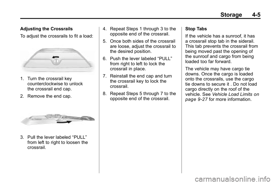
Adjusting the Crossrails
To adjust the crossrails to fit a load:
1. Turn the crossrail keycounterclockwise to unlock
the crossrail end cap.
2. Remove the end cap.
3. Pull the lever labeled “PULL”
from left to right to loosen the
crossrail. 4. Repeat Steps 1 through 3 to the
opposite end of the crossrail.
5. Once both sides of the crossrail are loose, adjust the crossrail to
the desired position.
6. Push the lever labeled “PULL”
from right to left to lock the
crossrail in place.
7. Reinstall the end cap and turn the crossrail key to lock the
crossrail.
8. Repeat Steps 5 through 7 to the opposite end of the crossrail. Stop Tabs
If the vehicle has a sunroof, it has
a crossrail stop tab in the siderail.
This tab prevents the crossrail from
being moved past the opening of
the sunroof and cargo from being
loaded too far forward.
The vehicle may have cargo tie
downs. Once the cargo is loaded
onto the crossrails, use the cargo
tie downs to secure it . Do not load
cargo directly on the roof of the
vehicle. See
Vehicle Load Limits
on
page 9‑27for more information.
Page 114 of 410

4-6 Storage
2NOTES
Page 115 of 410
Instruments and Controls 5-1
Instruments and
Controls
Controls
Steering Wheel Adjustment . . . 5-2
Horn . . . . . . . . . . . . . . . . . . . . . . . . . . 5-2
Windshield Wiper/Washer . . . . . 5-2
Rear Window Wiper/Washer . . . . . . . . . . . . . . . . . . . . . . 5-3
Compass . . . . . . . . . . . . . . . . . . . . . 5-3
Clock . . . . . . . . . . . . . . . . . . . . . . . . . 5-4
Power Outlets . . . . . . . . . . . . . . . . . 5-5
Cigarette Lighter . . . . . . . . . . . . . . 5-5
Ashtrays . . . . . . . . . . . . . . . . . . . . . . 5-6
Warning Lights, Gauges, and
Indicators
Warning Lights, Gauges, and Indicators . . . . . . . . . . . . . . . . . . . . 5-6
Instrument Cluster . . . . . . . . . . . . 5-7
Speedometer . . . . . . . . . . . . . . . . . 5-8
Odometer . . . . . . . . . . . . . . . . . . . . . 5-8
Trip Odometer . . . . . . . . . . . . . . . . . 5-8 Tachometer . . . . . . . . . . . . . . . . . . . 5-8
Fuel Gauge . . . . . . . . . . . . . . . . . . . 5-8
Engine Coolant Temperature
Gauge . . . . . . . . . . . . . . . . . . . . . . . 5-9
Safety Belt Reminders . . . . . . . . 5-9
Airbag Readiness Light . . . . . . 5-10
Passenger Airbag Status
Indicator . . . . . . . . . . . . . . . . . . . . 5-11
Charging System Light . . . . . . . 5-11
Malfunction Indicator Lamp . . . . . . . . . . . . . 5-12
Brake System Warning Light . . . . . . . . . . . . . . . . . . . . . . . 5-14
Antilock Brake System (ABS) Warning Light . . . . . . . . . . . . . . 5-15
Up-Shift Light . . . . . . . . . . . . . . . . 5-15
Traction Control System (TCS)/StabiliTrak
®Light . . . . 5-16
Tire Pressure Light . . . . . . . . . . 5-16
Engine Oil Pressure Light . . . . 5-17
Security Light . . . . . . . . . . . . . . . . 5-17
High-Beam on Light . . . . . . . . . 5-17
Cruise Control Light . . . . . . . . . 5-18
Information Displays
Driver Information Center (DIC) . . . . . . . . . . . . . . . 5-18
Vehicle Messages
Vehicle Messages . . . . . . . . . . . 5-21
Battery Voltage and ChargingMessages . . . . . . . . . . . . . . . . . . 5-21
Brake System Messages . . . . 5-22
Door Ajar Messages . . . . . . . . . 5-22
Engine Cooling System Messages . . . . . . . . . . . . . . . . . . 5-23
Engine Oil Messages . . . . . . . . 5-23
Engine Power Messages . . . . 5-23
Fuel System Messages . . . . . . 5-24
Lamp Messages . . . . . . . . . . . . . 5-24
Ride Control System Messages . . . . . . . . . . . . . . . . . . 5-24
Service Vehicle Messages . . . 5-25
Tire Messages . . . . . . . . . . . . . . . 5-25
Transmission Messages . . . . . 5-25
Universal Remote System
Universal Remote System . . . 5-26
Universal Remote System Programming . . . . . . . . . . . . . . . 5-26
Universal Remote System Operation . . . . . . . . . . . . . . . . . . 5-30
Page 116 of 410
5-2 Instruments and Controls
Controls
Steering Wheel
Adjustment
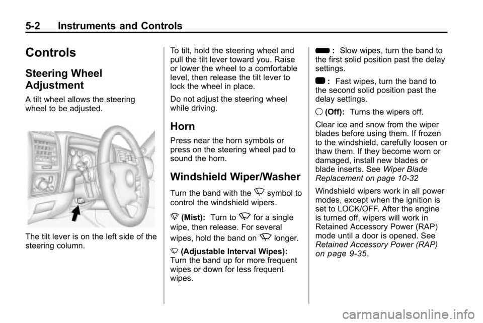
A tilt wheel allows the steering
wheel to be adjusted.
The tilt lever is on the left side of the
steering column.To tilt, hold the steering wheel and
pull the tilt lever toward you. Raise
or lower the wheel to a comfortable
level, then release the tilt lever to
lock the wheel in place.
Do not adjust the steering wheel
while driving.
Horn
Press near the horn symbols or
press on the steering wheel pad to
sound the horn.
Windshield Wiper/Washer
Turn the band with theNsymbol to
control the windshield wipers.
8 (Mist): Turn to
zfor a single
wipe, then release. For several
wipes, hold the band on
zlonger.
N (Adjustable Interval Wipes):
Turn the band up for more frequent
wipes or down for less frequent
wipes. 6
:Slow wipes, turn the band to
the first solid position past the delay
settings.
1 :Fast wipes, turn the band to
the second solid position past the
delay settings.
9 (Off): Turns the wipers off.
Clear ice and snow from the wiper
blades before using them. If frozen
to the windshield, carefully loosen or
thaw them. If they become worn or
damaged, install new blades or
blade inserts. See Wiper Blade
Replacement on page 10‑32
Windshield wipers work in all power
modes, except when the ignition is
set to LOCK/OFF. After the engine
is turned off, wipers will work in
Retained Accessory Power (RAP)
mode until a door is opened. See
Retained Accessory Power (RAP)
on page 9‑35.
Page 117 of 410
Instruments and Controls 5-3
Windshield Washer
L(Washer Fluid): To spray
washer fluid on the windshield, push
the paddle marked with
Lat the
top of the turn signal/lane change
lever. The wipers will clear the
window and then either stop or
return to the preset speed.
{WARNING
In freezing weather, do not use
your washer until the windshield
is warmed. Otherwise the
washer fluid can form ice on the
windshield, blocking your vision.
Rear Window
Wiper/Washer
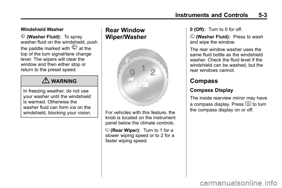
For vehicles with this feature, the
knob is located on the instrument
panel below the climate controls.
Z (Rear Wiper): Turn to 1 for a
slower wiping speed or to 2 for a
faster wiping speed. 0 (Off):
Turn to 0 for off.
= (Washer Fluid): Press to wash
and wipe the window.
The rear window washer uses the
same fluid bottle as the windshield
washer. Check the fluid level if the
windshield can be washed, but the
rear windows cannot.
Compass
Compass Display
The inside rearview mirror may have
a compass display. Press
zto turn
the compass display on or off.
Page 118 of 410

5-4 Instruments and Controls
Compass Calibration
The compass may need to be
calibrated if CAL is not displayed
and the compass requires
calibration. Press and hold
Ountil
CAL displays in the compass
window, then release the button.
The compass is now in
calibration mode.
.Drive the vehicle in circles
at less than 8 km/h (5 mph)
until CAL is no longer displayed
in the compass window. Then
continue to drive to make sure
all eight directions are available.
.Drive the vehicle under normal
operating conditions.
Compass Variance
The mirror is set to zone eight.
If you do not live in zone eight or
drive out of the area, the compass
variance needs to be changed to
the appropriate zone. To adjust for compass variance:
1. Find your current location and
variance zone number on the
following zone map.
2. Press and holdOfor
six seconds until ZONE
displays. Release the button.
The compass is now in
zone mode. 3. Keep pressing
Ountil the
desired zone number displays.
Release the button. After
four seconds, the new zone
number locks in and the
compass display returns.
Clock
The clock can be set with the
ignition on or off. Use the H and
M buttons located on the lower left
side of the radio.
To set the clock:
1. Press and hold H until the correct hour and AM or PM
displays.
2. Press and hold M until the correct minute displays.
Press DISP (Display) to display the
time while the ignition is turned off.
Page 119 of 410
Instruments and Controls 5-5
Power Outlets
The accessory power outlets can be
used to connect auxiliary electrical
equipment, such as a cellular
phone.
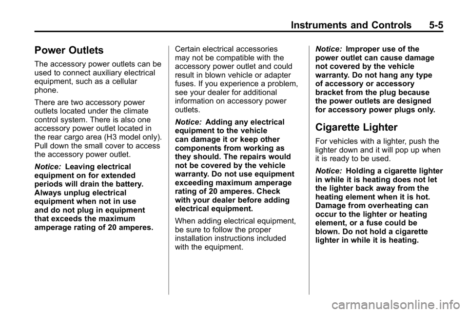
There are two accessory power
outlets located under the climate
control system. There is also one
accessory power outlet located in
the rear cargo area (H3 model only).
Pull down the small cover to access
the accessory power outlet.
Notice:Leaving electrical
equipment on for extended
periods will drain the battery.
Always unplug electrical
equipment when not in use
and do not plug in equipment
that exceeds the maximum
amperage rating of 20 amperes. Certain electrical accessories
may not be compatible with the
accessory power outlet and could
result in blown vehicle or adapter
fuses. If you experience a problem,
see your dealer for additional
information on accessory power
outlets.
Notice:
Adding any electrical
equipment to the vehicle
can damage it or keep other
components from working as
they should. The repairs would
not be covered by the vehicle
warranty. Do not use equipment
exceeding maximum amperage
rating of 20 amperes. Check
with your dealer before adding
electrical equipment.
When adding electrical equipment,
be sure to follow the proper
installation instructions included
with the equipment. Notice:
Improper use of the
power outlet can cause damage
not covered by the vehicle
warranty. Do not hang any type
of accessory or accessory
bracket from the plug because
the power outlets are designed
for accessory power plugs only.
Cigarette Lighter
For vehicles with a lighter, push the
lighter down and it will pop up when
it is ready to be used.
Notice: Holding a cigarette lighter
in while it is heating does not let
the lighter back away from the
heating element when it is hot.
Damage from overheating can
occur to the lighter or heating
element, or a fuse could be
blown. Do not hold a cigarette
lighter in while it is heating.
Page 120 of 410

5-6 Instruments and Controls
Ashtrays
For vehicles with a removable
ashtray, it can be placed into the
cupholder and be removed for
cleaning.
Notice:If papers, pins, or other
flammable items are put in the
ashtray, hot cigarettes or other
smoking materials could ignite
them and possibly damage the
vehicle. Never put flammable
items in the ashtray.
Warning Lights,
Gauges, and
Indicators
Warning lights and gauges can
signal that something is wrong
before it becomes serious enough
to cause an expensive repair or
replacement. Paying attention to the
warning lights and gauges could
prevent injury.
Warning lights come on when there
could be a problem with a vehicle
function. Some warning lights come
on briefly when the engine is started
to indicate they are working. Gauges can indicate when there
could be a problem with a vehicle
function. Often gauges and warning
lights work together to indicate a
problem with the vehicle.
When one of the warning lights
comes on and stays on while
driving, or when one of the gauges
shows there may be a problem,
check the section that explains what
to do. Follow this manual's advice.
Waiting to do repairs can be costly
and even dangerous.