Lamp Hyundai Accent 2007 Owner's Manual
[x] Cancel search | Manufacturer: HYUNDAI, Model Year: 2007, Model line: Accent, Model: Hyundai Accent 2007Pages: 282, PDF Size: 10.55 MB
Page 169 of 282
2 DRIVING YOUR HYUNDAI
6
!
C055B01B-GAT STARTING AND STOPPING THE ENGINE FOR TURBO CHARGERINTERCOOLER (Diesel Engine)
(1) Do not race the engine or sudden
accelerate the engine immediately after start it. If the engine is cold,allow the engine to idle for several seconds before it is driven to en- sure sufficient lubrication of theturbo charger unit.
(2) After high speed or extended driv-
ing, requiring a heavy engine load,the engine should be allowed to idle about 1 minute before turning it off. This idle time will allow the turbocharger to cool prior to shutting the engine off.
WARNING:
Do not turn the engine off immedi- ately after it has been subjected to a heavy load. Doing so may cause severe damage to the engine orturbo charger unit.
!
C050B01HP
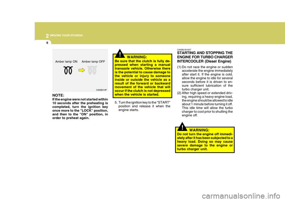
NOTE: If the engine were not started within 10 seconds after the preheating is completed, turn the ignition key once more to the "LOCK" position,and then to the "ON" position, in order to preheat again. WARNING:
Be sure that the clutch is fully de-pressed when starting a manual transaxle vehicle. Otherwise there
is the potential to cause damage to the vehicle or injury to someone inside or outside the vehicle as aresult of the forward or backward movement of the vehicle that will occur if the clutch is not depressedwhen the vehicle is started.
5. Turn the ignition key to the "START" position and release it when the engine starts.
Amber lamp ON Amber lamp OFF
Page 192 of 282
3
WHAT TO DO IN AN EMERGENCY
3
!
JUMP STARTING
WARNING:
The gas produced by the battery during the jump-start operation ishighly explosive. If these instruc- tions are not followed exactly, seri- ous personal injury and damage tothe vehicle may occur! If you are not sure how to follow this proce- dure, seek qualified assistance.Automobile batteries contain sul- furic acid. This is poisonous and highly corrosive. When jump start-ing, wear protective glasses and be careful not to get acid on yourself, your clothing or on the car. 1. If the booster battery is installed in
another vehicle, be sure the twovehicles are not touching.
2. Turn off all unnecessary lights and
accessories in both vehicles.
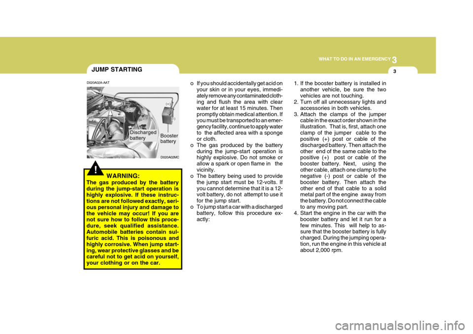
3. Attach the clamps of the jumper cable in the exact order shown in theillustration. That is, first, attach oneclamp of the jumper cable to the positive (+) post or cable of the discharged battery. Then attach theother end of the same cable to the positive (+) post or cable of the booster battery. Next, using theother cable, attach one clamp to the negative (-) post or cable of the booster battery. Then attach theother end of that cable to a solid metal part of the engine away from the battery. Do not connect the cableto any moving part.
4. Start the engine in the car with the
booster battery and let it run for afew minutes. This will help to as- sure that the booster battery is fully charged. During the jumping opera-tion, run the engine in this vehicle at about 2,000 rpm.
D020A02A-AAT
o If you should accidentally get acid on
your skin or in your eyes, immedi- ately remove any contaminated cloth- ing and flush the area with clear water for at least 15 minutes. Thenpromptly obtain medical attention. If you must be transported to an emer- gency facility, continue to apply waterto the affected area with a sponge or cloth.
o The gas produced by the battery during the jump-start operation ishighly explosive. Do not smoke or allow a spark or open flame in thevicinity.
o The battery being used to provide
the jump start must be 12-volts. Ifyou cannot determine that it is a 12- volt battery, do not attempt to use it for the jump start.
o To jump start a car with a discharged battery, follow this procedure ex-actly:
Booster battery
D020A02MC
Discharged battery
Page 221 of 282
5
VEHICLE MAINTENANCE REQUIREMENTS
9
F060H01A-AAT
o Air Cleaner Filter A Genuine Hyundai air cleaner filter is
recommended when the filter is re- placed. F060J01A-AAT
o Spark Plugs (For Gasoline Engine)
Make sure to install new spark plugs of the correct heat range. F070C01A-AAT o Coolant The coolant should be changed at the intervals specified in the mainte- nance schedule.
F060E01MC-AAT
o Timing Belt (Gasoline)
Inspect all parts related to the timing
belt for damage and deformation.Replace any damaged parts immedi- ately.
F060G01A-AAT
o Vapor Hose and Fuel Filler Cap
The vapor hose and fuel filler cap
should be inspected at those intervalsspecified in the maintenance sched-ule. Make sure that a new vapor hose or fuel filler cap is correctly replaced. F060F01A-AAT
o Vacuum, Crankcase Ventila-
tion Hoses
Inspect the surface of hoses for evi-
dence of heat and/or mechanical dam-age. Hard and brittle rubber, cracking, tears, cuts, abrasions, and excessiveswelling indicate deterioration. Partic- ular attention should be paid to exam- ine those hose surfaces nearest tohigh heat sources, such as the ex- haust manifold.
Inspect the hose routing to assure
that the hoses do not come in contactwith any heat source, sharp edges or moving component which might causeheat damage or mechanical wear. Inspect all hose connections, such as clamps and couplings, to make surethey are secure, and that no leaks are present. Hoses should be replaced immediately if there is any evidenceof deterioration or damage. F070B01A-GAT o Cooling System Check the cooling system part, such as radiator, coolant reservoir, hoses and connections for leakage and dam- age. Replace any damaged parts.
Page 223 of 282
5
VEHICLE MAINTENANCE REQUIREMENTS
11
F070M01A-AAT
o Steering Gear Box, Linkage &
Boots/Lower arm Ball Joint
With the vehicle stopped and engine off, check for excessive free-play in the steering wheel. Check the linkage for bends or damage. Check the dustboots and ball joints for deterioration, cracks, or damage. Replace any dam- aged parts. F070N01A-AAT
o Power Steering Pump, Belt
and Hoses
Check the power steering pump and hoses for leakage and damage. Re- place any damaged or leaking partsimmediately. Inspect the power steer- ing belt for evidence of cuts, cracks, excessive wear, oiliness and propertension. Replace or adjust it if neces- sary. F070P01A-AAT
o Drive Shafts and Boots
Check the drive shafts, boots and clamps for cracks, deterioration, or damage. Replace any damaged parts and, if necessary, repack the grease. F070Q01A-AAT
o Air Conditioning Refrigerant
Check the air conditioning lines and connections for leakage and damage. Check air conditioning performance according to the relevant shop manual if necessary.
Page 245 of 282
6 DO-IT-YOURSELF MAINTENANCE
22
!
CHECKING THE BATTERY
G210A01A-AAT
WARNING:
Batteries can be dangerous! When working with batteries, carefully ob-serve the following precautions to avoid serious injuries. The fluid in the battery contains a strong solution of sulfuric acid, which is poi- sonous and highly corrosive. Be careful not to spill it on yourself or the car. If youdo spill battery fluid on yourself, imme- diately do the following:
OMC055018
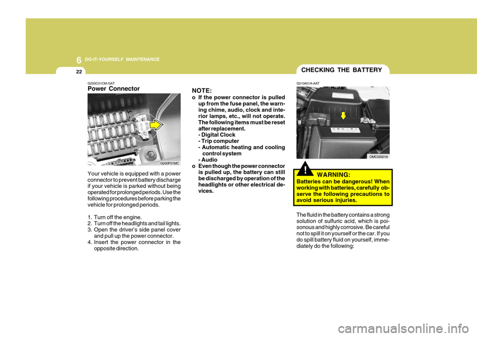
G200C01CM-GAT Power Connector
NOTE:
o If the power connector is pulled
up from the fuse panel, the warn- ing chime, audio, clock and inte- rior lamps, etc., will not operate. The following items must be resetafter replacement. - Digital Clock - Trip computer
- Automatic heating and cooling control system
- Audio
o Even though the power connector is pulled up, the battery can stillbe discharged by operation of theheadlights or other electrical de- vices.
Your vehicle is equipped with a power connector to prevent battery discharge if your vehicle is parked without being operated for prolonged periods. Use thefollowing procedures before parking the vehicle for prolonged periods.
1. Turn off the engine.
2. Turn off the headlights and tail lights.
3. Open the driver’s side panel cover
and pull up the power connector.
4. Insert the power connector in the
opposite direction.
G200F01MC
Page 250 of 282
6
DO-IT-YOURSELF MAINTENANCE
27REPLACEMENT OF LIGHT BULBS
SPECIFICATIONS: "H" Horizontal center line of headlights from ground.: 665 mm (26.18 in.) "W" Distance between each headlight center. : 1,170 mm (46.06 in.) "L" Distance between the headlightsand the wall that the lights are tested against. : 3,000 mm (118.11 in.). G260A01MC-AAT Before attempting to replace a light bulb, be sure the switch is turned to the "OFF" position.The next paragraph shows how to reach the light bulbs so they may be changed. Be sure to replace the burned-out bulbwith one of the same number and watt- age rating. See page 6-34 for the wattage descrip-tions.
CAUTION:
o Keep the lamps out of contact with petroleum products, such as oil,gasoline, etc.
o If you don't have necessary tools,
the correct bulbs and the exper-tise, consult your authorized Hyundai dealer.
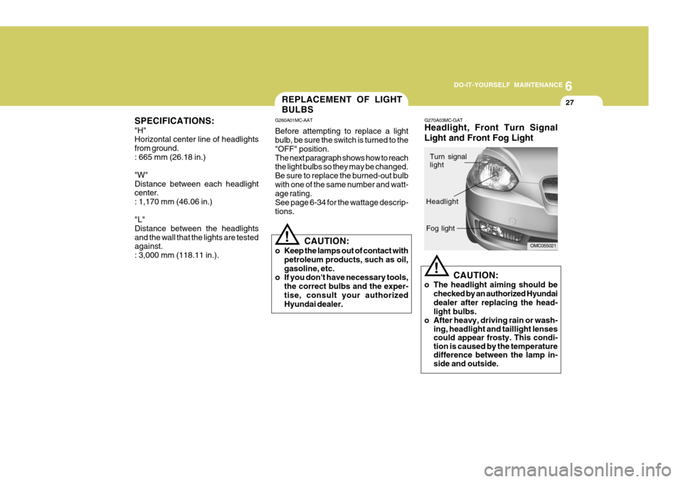
! G270A03MC-GAT Headlight, Front Turn Signal Light and Front Fog Light
CAUTION:
o The headlight aiming should be checked by an authorized Hyundai dealer after replacing the head- light bulbs.
o After heavy, driving rain or wash- ing, headlight and taillight lenses could appear frosty. This condi-tion is caused by the temperaturedifference between the lamp in-side and outside.
!
OMC055021
Turn signal light
Headlight Fog light
Page 251 of 282
6 DO-IT-YOURSELF MAINTENANCE
28
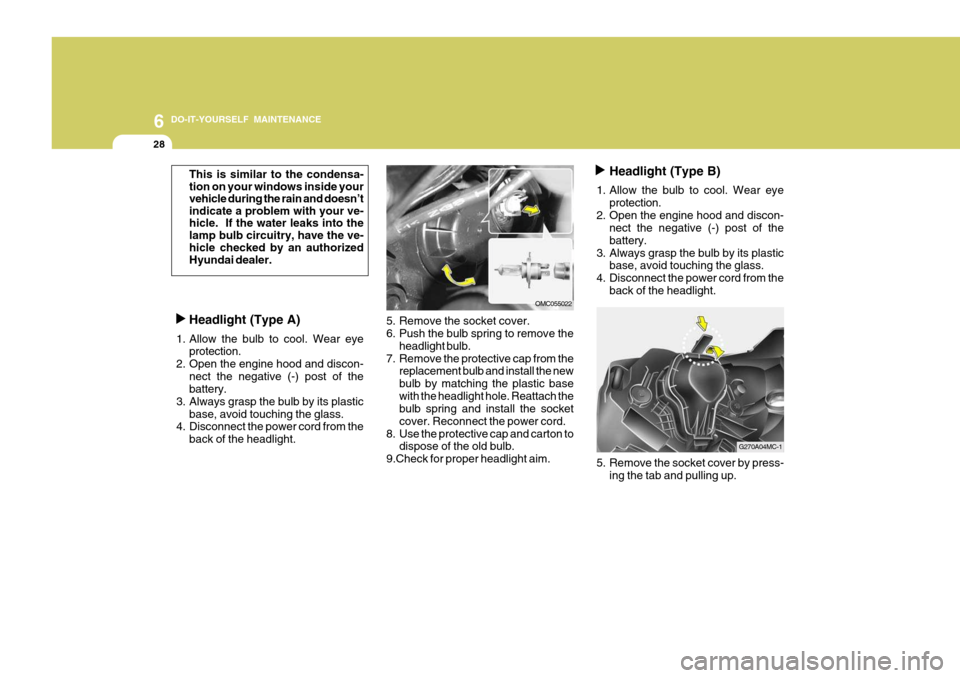
5. Remove the socket cover.
6. Push the bulb spring to remove theheadlight bulb.
7. Remove the protective cap from the replacement bulb and install the new bulb by matching the plastic basewith the headlight hole. Reattach the bulb spring and install the socket cover. Reconnect the power cord.
8. Use the protective cap and carton to dispose of the old bulb.
9.Check for proper headlight aim.
Headlight (Type A)
1. Allow the bulb to cool. Wear eye protection.
2. Open the engine hood and discon- nect the negative (-) post of the battery.
3. Always grasp the bulb by its plastic base, avoid touching the glass.
4. Disconnect the power cord from the
back of the headlight.
This is similar to the condensa- tion on your windows inside yourvehicle during the rain and doesn’tindicate a problem with your ve-hicle. If the water leaks into thelamp bulb circuitry, have the ve- hicle checked by an authorizedHyundai dealer.
OMC055022Headlight (Type B)
1. Allow the bulb to cool. Wear eye protection.
2. Open the engine hood and discon- nect the negative (-) post of the battery.
3. Always grasp the bulb by its plastic base, avoid touching the glass.
4. Disconnect the power cord from the
back of the headlight.
5. Remove the socket cover by press-ing the tab and pulling up.
G270A04MC-1
Page 254 of 282
6
DO-IT-YOURSELF MAINTENANCE
31
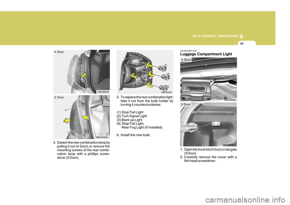
5. To replace the rear combination light, take it out from the bulb holder by turning it counterclockwise.
(1) Stop/Tail Light (2) Turn Signal Light(3) Back-up Light
(4) Stop/Tail Light, Rear Fog Light (If Installed)
6. Install the new bulb.
4.
Detach the rear combination lamp by pulling it out (4 Door) or remove the mounting screws of the rear combi- nation lamp with a phillips screw-driver (3 Door).
OMC055027OMC055026
4 Door
OMC055026-1
3 Door
OMC055028-1
G270C01MC-GAT Luggage Compartment Light
OMC055028
1. Open the trunk lid (4 Door) or tail gate (3 Door).
2. Carefully remove the cover with a flat-head screwdriver.
4 Door
3 Door
Page 259 of 282
6 DO-IT-YOURSELF MAINTENANCE
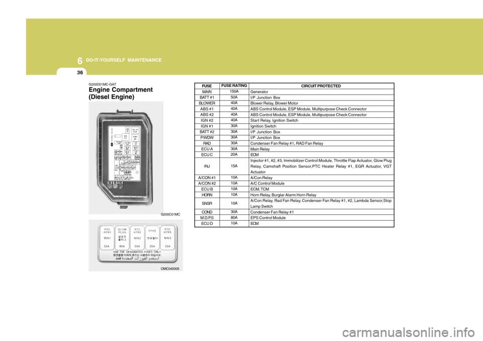
36
G200D01MC-GAT Engine Compartment (Diesel Engine) FUSE RATING
150A50A 40A 40A 40A40A 30A 30A30A 30A 30A20A 15A10A 10A10A 10A 10A30A 80A10A CIRCUIT PROTECTED
Generator I/P Junction Box
Blower Relay, Blower MotorABS Control Module, ESP Module, Multipurpose Check Connector ABS Control Module, ESP Module, Multipurpose Check Connector
Start Relay, Ignition SwitchIgnition Switch I/P Junction Box I/P Junction BoxCondenser Fan Relay #1, RAD Fan Relay Main Relay ECMInjector #1, #2, #3, Immobilizer Control Module, Throttle Flap Actuator, Glow Plug
Relay, Camshaft Position Sensor,PTC Heater Relay #1, EGR Actuator, VGT ActuatorA/Con RelayA/C Control Module ECM, TCM
Horn Relay, Burglar Alarm Horn Relay
A/Con Relay, Rad Fan Relay, Condenser Fan Relay #1, #2, Lambda Sensor,Stop Lamp Switch Condenser Fan Relay #1EPS Control Module ECM
MAIN
BATT #1
BLOWER
ABS #1 ABS #2IGN #2 IGN #1
BATT #2 P/WDW
RAD
ECU A ECU C
INJ
A/CON #1A/CON #2 ECU B
HORN
SNSR
COND
M.D.P.S ECU D
FUSE
OMC045005
G200C01MC
Page 260 of 282
6
DO-IT-YOURSELF MAINTENANCE
37
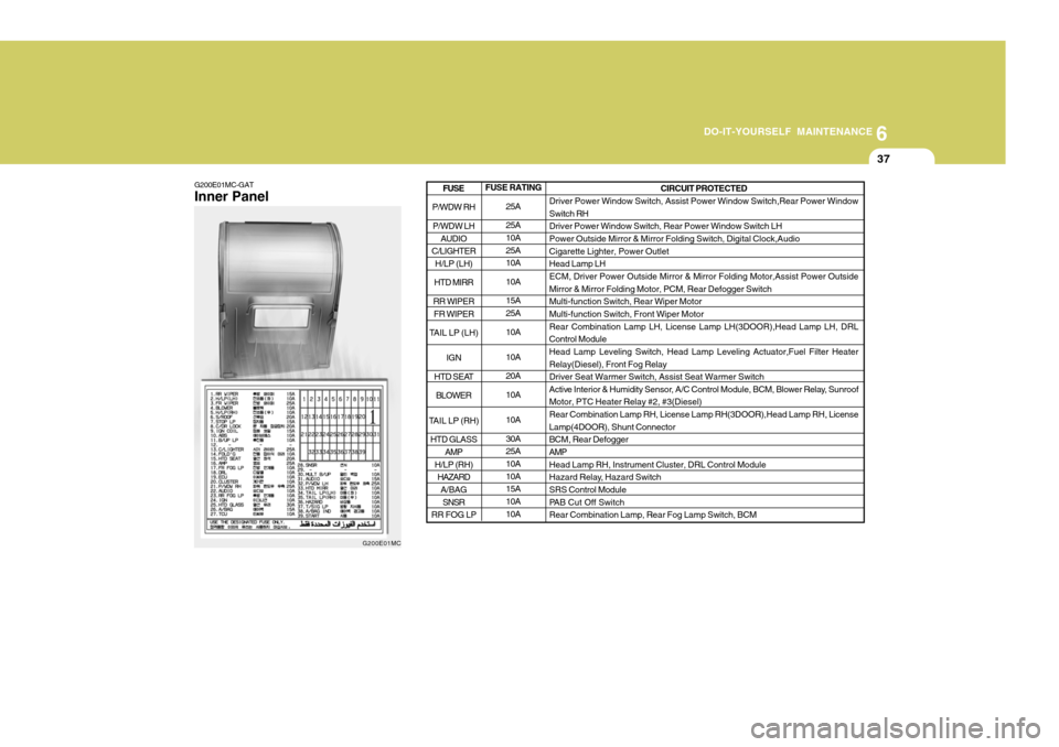
G200E01MC-GAT Inner Panel FUSE RATING
25A 25A 10A 25A10A 10A15A 25A 10A 10A 20A10A 10A 30A 25A 10A 10A15A 10A 10A CIRCUIT PROTECTED
Driver Power Window Switch, Assist Power Window Switch,Rear Power Window Switch RH Driver Power Window Switch, Rear Power Window Switch LHPower Outside Mirror & Mirror Folding Switch, Digital Clock,Audio Cigarette Lighter, Power Outlet Head Lamp LHECM, Driver Power Outside Mirror & Mirror Folding Motor,Assist Power Outside Mirror & Mirror Folding Motor, PCM, Rear Defogger Switch Multi-function Switch, Rear Wiper MotorMulti-function Switch, Front Wiper Motor Rear Combination Lamp LH, License Lamp LH(3DOOR),Head Lamp LH, DRL Control ModuleHead Lamp Leveling Switch, Head Lamp Leveling Actuator,Fuel Filter Heater Relay(Diesel), Front Fog Relay Driver Seat Warmer Switch, Assist Seat Warmer Switch
Active Interior & Humidity Sensor, A/C Control Module, BCM, Blower Relay, SunroofMotor, PTC Heater Relay #2, #3(Diesel) Rear Combination Lamp RH, License Lamp RH(3DOOR),Head Lamp RH, License Lamp(4DOOR), Shunt ConnectorBCM, Rear Defogger AMP Head Lamp RH, Instrument Cluster, DRL Control Module
Hazard Relay, Hazard Switch SRS Control Module
PAB Cut Off SwitchRear Combination Lamp, Rear Fog Lamp Switch, BCM
P/WDW RH
P/WDW LH AUDIO
C/LIGHTER H/LP (LH)
HTD MIRR
RR WIPER FR WIPER
TAIL LP (LH)
IGN
HTD SEAT BLOWER
TAIL LP (RH) HTD GLASS AMP
H/LP (RH) HAZARD
A/BAG
SNSR
RR FOG LP
FUSE
G200E01MC