clock Hyundai Accent 2008 User Guide
[x] Cancel search | Manufacturer: HYUNDAI, Model Year: 2008, Model line: Accent, Model: Hyundai Accent 2008Pages: 273, PDF Size: 9.36 MB
Page 152 of 273
DRIVING YOUR HYUNDAI
52
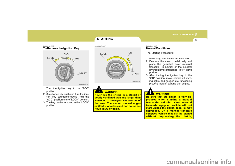
C070C01A-AATTo Remove the Ignition Key1. Turn the ignition key to the "ACC"
position.
2. Simultaneously push and turn the igni-
tion key counterclockwise from the
"ACC" position to the "LOCK" position.
3. The key can be removed in the "LOCK"
position.
C070C01E-1
LOCKACC
ON
START
STARTINGC050A01A-AAT
WARNING:
Never run the engine in a closed or
poorly ventilated area any longer than
is needed to move your car in or out of
the area. The carbon monoxide gas
emitted is odorless and can cause se-
rious injury or death.
C050A01E-1
!LOCKON
START
C050B02A-AATNormal Conditions:The Starting Procedure:
1. Insert key, and fasten the seat belt.
2. Depress the clutch pedal fully and
place the gearshift lever (manual
transaxle) in neutral or the selector
lever (automatic transaxle) in "P" (park)
position.
3. After turning the ignition key to the
"ON" position, make certain all warn-
ing lights and gauges are functioning
properly before starting the engine.
WARNING:
Be sure that the clutch is fully de-
pressed when starting a manual
transaxle vehicle. Your manual
transaxle equipped vehicle will not
start unless the clutch pedal is fully
depressed. On a manual transaxle
equipped vehicle that can be started
without depressing the clutch,
!
Page 185 of 273
3
WHAT TO DO IN AN EMERGENCY
13
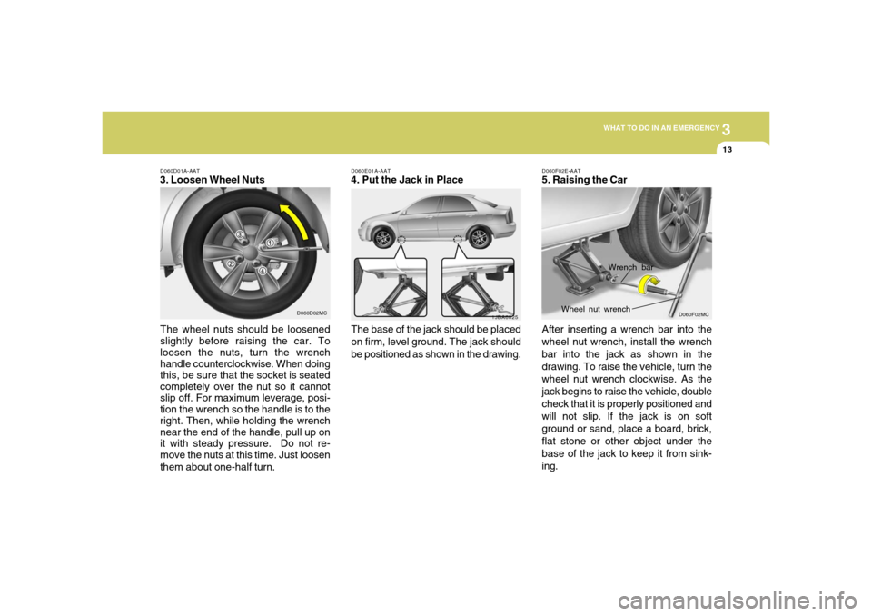
D060E01A-AAT4. Put the Jack in Place
The base of the jack should be placed
on firm, level ground. The jack should
be positioned as shown in the drawing.
1JBA6025
D060D01A-AAT3. Loosen Wheel Nuts
The wheel nuts should be loosened
slightly before raising the car. To
loosen the nuts, turn the wrench
handle counterclockwise. When doing
this, be sure that the socket is seated
completely over the nut so it cannot
slip off. For maximum leverage, posi-
tion the wrench so the handle is to the
right. Then, while holding the wrench
near the end of the handle, pull up on
it with steady pressure. Do not re-
move the nuts at this time. Just loosen
them about one-half turn.
D060D02MC
D060F02E-AAT5. Raising the Car
After inserting a wrench bar into the
wheel nut wrench, install the wrench
bar into the jack as shown in the
drawing. To raise the vehicle, turn the
wheel nut wrench clockwise. As the
jack begins to raise the vehicle, double
check that it is properly positioned and
will not slip. If the jack is on soft
ground or sand, place a board, brick,
flat stone or other object under the
base of the jack to keep it from sink-
ing.
Wrench bar
Wheel nut wrench
D060F02MC
Page 187 of 273
3
WHAT TO DO IN AN EMERGENCY
15
!
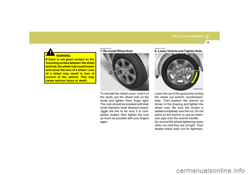
D060H02A-AAT7. Re-install Wheel Nuts
To reinstall the wheel cover, hold it on
the studs, put the wheel nuts on the
studs and tighten them finger tight.
The nuts should be installed with their
small diameter ends directed inward.
Jiggle the tire to be sure it is com-
pletely seated, then tighten the nuts
as much as possible with your fingers
again.
D060H03MC
WARNING:
If there is not good contact on the
mounting surface between the wheel
and hub, the wheel nuts could loosen
and cause the loss of a wheel. Loss
of a wheel may result in loss of
control of the vehicle. This may
cause serious injury or death.
D060I01E-GAT8. Lower Vehicle and Tighten Nuts
Lower the car to the ground by turning
the wheel nut wrench counterclock-
wise. Then position the wrench as
shown in the drawing and tighten the
wheel nuts. Be sure the socket is
seated completely over the nut. Do not
stand on the wrench or use an exten-
sion pipe over the wrench handle.
Go around the wheel tightening every
other nut until they are all tight. Then
double-check each nut for tightness.
OMC047009
Page 191 of 273
3
WHAT TO DO IN AN EMERGENCY
19
CAUTION:
If the car is being towed with all four
wheels on the ground, it can be towed
only from the front. Be sure that the
transaxle is in neutral. Do not tow at
speeds greater than 30 mph (50 km/h)
and for more than 15 miles (25 km). Be
sure the steering is unlocked by plac-
ing the key in the "ACC" position. A
driver must be in the towed vehicle to
operate the steering and brakes.
!
OMC045013
OMC045014
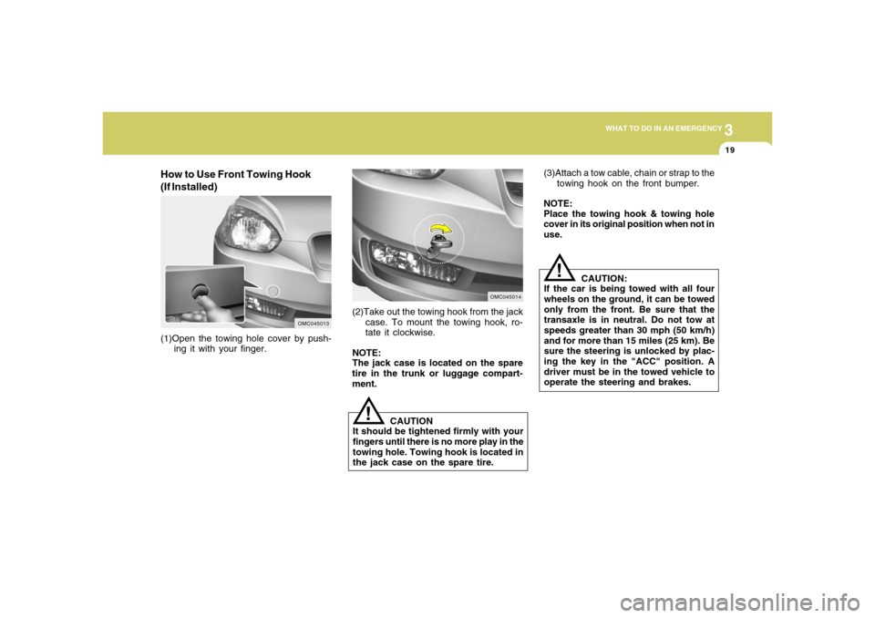
(1)Open the towing hole cover by push-
ing it with your finger.(2)Take out the towing hook from the jack
case. To mount the towing hook, ro-
tate it clockwise.
NOTE:
The jack case is located on the spare
tire in the trunk or luggage compart-
ment.
!
CAUTION
It should be tightened firmly with your
fingers until there is no more play in the
towing hole. Towing hook is located in
the jack case on the spare tire.
How to Use Front Towing Hook
(If Installed)
(3)Attach a tow cable, chain or strap to the
towing hook on the front bumper.
NOTE:
Place the towing hook & towing hole
cover in its original position when not in
use.
Page 215 of 273
6
DO-IT-YOURSELF MAINTENANCE6
!
CAUTION:
Slowly pour the recommended oil by
using a funnel. Do not overfill so as not
to damage engine.
!
WARNING:
Be very careful not to touch the radia-
tor hose when adding the engine oil as
it may be hot enough to burn you.
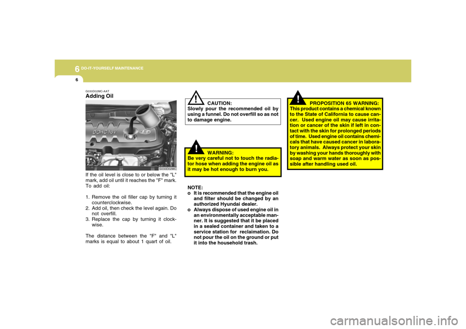
G030D02MC-AATAdding OilIf the oil level is close to or below the "L"
mark, add oil until it reaches the "F" mark.
To add oil:
1. Remove the oil filler cap by turning it
counterclockwise.
2. Add oil, then check the level again. Do
not overfill.
3. Replace the cap by turning it clock-
wise.
The distance between the "F" and "L"
marks is equal to about 1 quart of oil.
G030D02MC
NOTE:
o It is recommended that the engine oil
and filter should be changed by an
authorized Hyundai dealer.
o Always dispose of used engine oil in
an environmentally acceptable man-
ner. It is suggested that it be placed
in a sealed container and taken to a
service station for reclaimation. Do
not pour the oil on the ground or put
it into the household trash.
!
PROPOSITION 65 WARNING:
This product contains a chemical known
to the State of California to cause can-
cer. Used engine oil may cause irrita-
tion or cancer of the skin if left in con-
tact with the skin for prolonged periods
of time. Used engine oil contains chemi-
cals that have caused cancer in labora-
tory animals. Always protect your skin
by washing your hands thoroughly with
soap and warm water as soon as pos-
sible after handling used oil.
Page 227 of 273
6
DO-IT-YOURSELF MAINTENANCE
18
CAUTION:
An open fuse indicates that there is a
problem in the electrical circuit. If you
replace a fuse and it blows as soon as
the accessory is turned on, the prob-
lem is serious and should be referred to
a Hyundai dealer for diagnosis and re-
pair. Never replace a fuse with anything
except a fuse with the same or a lower
amperage rating. A higher capacity fuse
could cause damage and create a fire
hazard.
!
NOTE:
See page 6-29 for the fuse panel de-
scriptions.
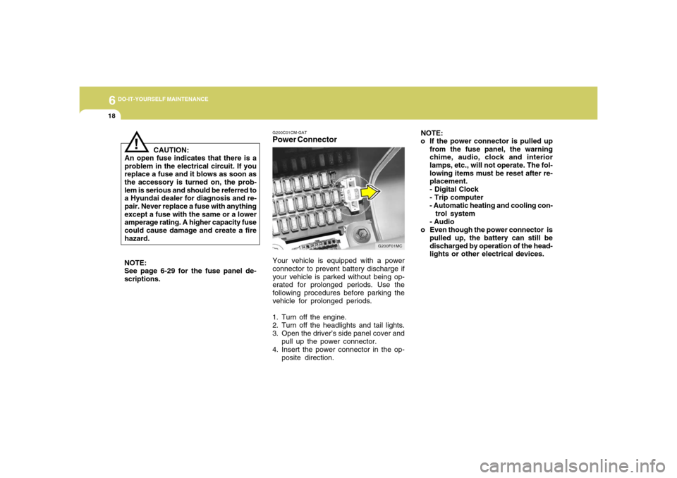
G200C01CM-GATPower Connector
NOTE:
o If the power connector is pulled up
from the fuse panel, the warning
chime, audio, clock and interior
lamps, etc., will not operate. The fol-
lowing items must be reset after re-
placement.
- Digital Clock
- Trip computer
- Automatic heating and cooling con-
trol system
- Audio
o Even though the power connector is
pulled up, the battery can still be
discharged by operation of the head-
lights or other electrical devices.
Your vehicle is equipped with a power
connector to prevent battery discharge if
your vehicle is parked without being op-
erated for prolonged periods. Use the
following procedures before parking the
vehicle for prolonged periods.
1. Turn off the engine.
2. Turn off the headlights and tail lights.
3. Open the driver’s side panel cover and
pull up the power connector.
4. Insert the power connector in the op-
posite direction.
G200F01MC
Page 232 of 273
6
DO-IT-YOURSELF MAINTENANCE
23
G270A03O
!
WARNING:
o When removing/replacing halogen
bulbs, always handle the metal body
of the bulb, not the glass.
o The halogen bulb contains gas under
pressure and if impacted could shat-
ter, resulting in flying fragments. Al-
ways wear eye protection when ser-
vicing the bulb. Protect the bulb
against abrasions or scratches and
against liquids when lighted. Turn
the bulb on only when installed in a
headlight. Replace the headlight if
damaged or cracked. Keep the bulb
out of the reach of children and dis-
pose of the used bulb with care.
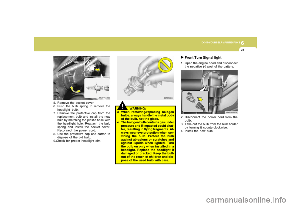
5. Remove the socket cover.
6. Push the bulb spring to remove the
headlight bulb.
7. Remove the protective cap from the
replacement bulb and install the new
bulb by matching the plastic base with
the headlight hole. Reattach the bulb
spring and install the socket cover.
Reconnect the power cord.
8. Use the protective cap and carton to
dispose of the old bulb.
9.Check for proper headlight aim.
OMC055022
Front Turn Signal light
1. Open the engine hood and disconnect
the negative (-) post of the battery.
2. Disconnect the power cord from the
bulb.
3. Take out the bulb from the bulb holder
by turning it counterclockwise.
4. Install the new bulb.
OMC055023
Page 234 of 273
6
DO-IT-YOURSELF MAINTENANCE
25
OMC055028-1
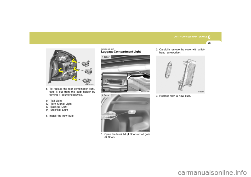
5. To replace the rear combination light,
take it out from the bulb holder by
turning it counterclockwise.
(1) Tail Light
(2) Turn Signal Light
(3) Back-up Light
(4) Stop/Tail Light
6. Install the new bulb.
OMC055027
G270C01MC-GATLuggage Compartment Light
OMC055028
1. Open the trunk lid (4 Door) or tail gate
(3 Door).
3. Replace with a new bulb.
HTB284
2. Carefully remove the cover with a flat-
head screwdriver.
4 Door3 Door
Page 239 of 273
6
DO-IT-YOURSELF MAINTENANCE
30
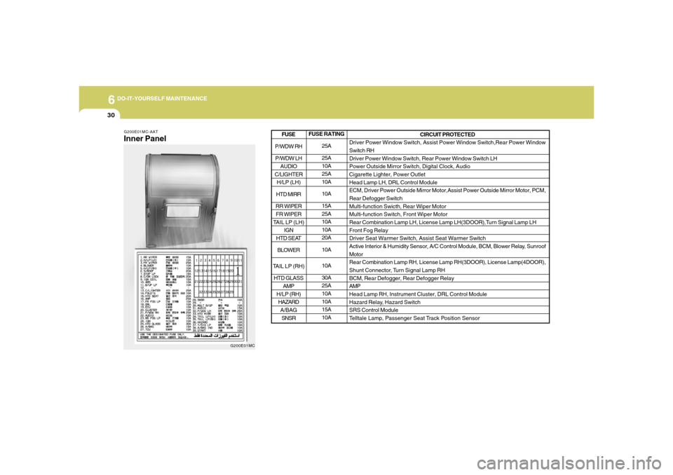
G200E01MC-AATInner Panel
G200E01MC
FUSE RATING
25A
25A
10A
25A
10A
10A
15A
25A
10A
10A
20A
10A
10A
30A
25A
10A
10A
15A
10ACIRCUIT PROTECTED
Driver Power Window Switch, Assist Power Window Switch,Rear Power Window
Switch RH
Driver Power Window Switch, Rear Power Window Switch LH
Power Outside Mirror Switch, Digital Clock, Audio
Cigarette Lighter, Power Outlet
Head Lamp LH, DRL Control Module
ECM, Driver Power Outside Mirror Motor,Assist Power Outside Mirror Motor, PCM,
Rear Defogger Switch
Multi-function Swicth, Rear Wiper Motor
Multi-function Switch, Front Wiper Motor
Rear Combination Lamp LH, License Lamp LH(3DOOR),Turn Signal Lamp LH
Front Fog Relay
Driver Seat Warmer Switch, Assist Seat Warmer Switch
Active Interior & Humidity Sensor, A/C Control Module, BCM, Blower Relay, Sunroof
Motor
Rear Combination Lamp RH, License Lamp RH(3DOOR), License Lamp(4DOOR),
Shunt Connector, Turn Signal Lamp RH
BCM, Rear Defogger, Rear Defogger Relay
AMP
Head Lamp RH, Instrument Cluster, DRL Control Module
Hazard Relay, Hazard Switch
SRS Control Module
Telltale Lamp, Passenger Seat Track Position Sensor
P/WDW RH
P/WDW LH
AUDIO
C/LIGHTER
H/LP (LH)
HTD MIRR
RR WIPER
FR WIPER
TAIL LP (LH)
IGN
HTD SEAT
BLOWER
TAIL LP (RH)
HTD GLASS
AMP
H/LP (RH)
HAZARD
A/BAG
SNSRFUSE
Page 240 of 273
6
DO-IT-YOURSELF MAINTENANCE
31
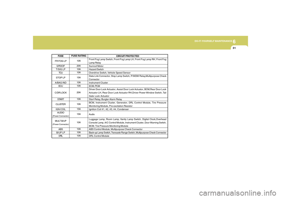
FUSE RATING
10A
20A
10A
10A
15A
10A
10A
20A
10A
10A
15A
15A
10A
10A
10A
10ACIRCUIT PROTECTED
Front Fog Lamp Switch, Front Fog Lamp LH, Front Fog Lamp RH, Front Fog
Lamp Relay
Sunroof Motor
Hazard Switch
Overdrive Switch, Vehicle Speed Sensor
Data Link Connector, Stop Lamp Switch, P/WDW Relay,Multipurpose Check
Connector
Instrument Cluster
ECM, PCM
Driver Door Lock Actuator, Assist Door Lock Actuator, BCM,Rear Door Lock
Actuator LH, Rear Door Lock Actuator RH,Driver Power Window Switch, Tail
Gate Lock Actuator
Star t Relay, Burglar Alarm Relay
BCM, Instrument Cluster, Generator, DRL Control Module, Tire Pressure
Monitoring Module, Pre-excitation Resistor
Ignition Coil #1, #2, #3, #4, Condenser
Audio
Luggage Lamp, Room Lamp, Vanity Lamp Switch, Digital Clock,Overhead
Console Lamp, A/C Control Module, Instrument Cluster, Door Warning Switch,
BCM, Tire Pressure Monitoring Module
ABS Control Module, Multipurpose Check Connector
Back-up Lamp Switch, Transaxle Range Switch, Multipurpose Check Connector
DRL Control Module
FR FOG LP
S/ROOF
T/SIG LP
TCU
STOP LP
A/BAG IND
ECU
C/DR LOCK
START
CLUSTER
IGN COIL
AUDIO(Power Connector)MULT B/UP(Power Connector)
ABS
B/UP LP
DRLFUSE