check engine Hyundai Accent 2010 Workshop Manual
[x] Cancel search | Manufacturer: HYUNDAI, Model Year: 2010, Model line: Accent, Model: Hyundai Accent 2010Pages: 284, PDF Size: 10.23 MB
Page 254 of 284
6 DO-IT-YOURSELF MAINTENANCE
28
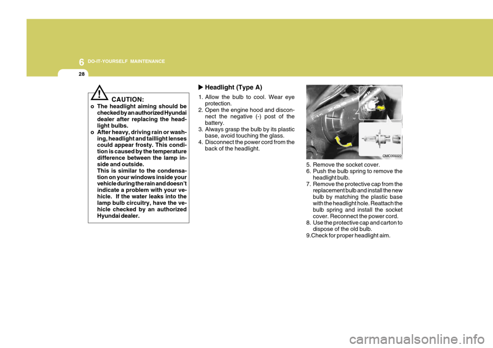
5. Remove the socket cover.
6. Push the bulb spring to remove theheadlight bulb.
7. Remove the protective cap from the replacement bulb and install the new bulb by matching the plastic basewith the headlight hole. Reattach the bulb spring and install the socket cover. Reconnect the power cord.
8. Use the protective cap and carton to dispose of the old bulb.
9.Check for proper headlight aim.
Headlight (Type A)
1. Allow the bulb to cool. Wear eye protection.
2. Open the engine hood and discon- nect the negative (-) post of the battery.
3. Always grasp the bulb by its plastic base, avoid touching the glass.
4. Disconnect the power cord from the back of the headlight.
OMC055022
CAUTION:
o The headlight aiming should be checked by an authorized Hyundai dealer after replacing the head- light bulbs.
o After heavy, driving rain or wash- ing, headlight and taillight lensescould appear frosty. This condi- tion is caused by the temperaturedifference between the lamp in- side and outside. This is similar to the condensa-tion on your windows inside your vehicle during the rain and doesn’t indicate a problem with your ve-hicle. If the water leaks into the lamp bulb circuitry, have the ve- hicle checked by an authorizedHyundai dealer.
!
Page 255 of 284
6
DO-IT-YOURSELF MAINTENANCE
29
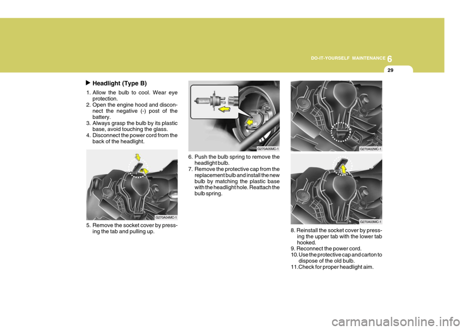
Headlight (Type B)
1. Allow the bulb to cool. Wear eye protection.
2. Open the engine hood and discon- nect the negative (-) post of the battery.
3. Always grasp the bulb by its plastic base, avoid touching the glass.
4. Disconnect the power cord from the
back of the headlight.
5. Remove the socket cover by press-ing the tab and pulling up. 6. Push the bulb spring to remove the
headlight bulb.
7. Remove the protective cap from the
replacement bulb and install the new bulb by matching the plastic base with the headlight hole. Reattach the bulb spring.8. Reinstall the socket cover by press-ing the upper tab with the lower tab hooked.
9. Reconnect the power cord.
10. Use the protective cap and carton to
dispose of the old bulb.
11.Check for proper headlight aim.
G270A04MC-1
G270A05MC-1G270A02MC-1
G270A03MC-1
Page 261 of 284
6
DO-IT-YOURSELF MAINTENANCE
35
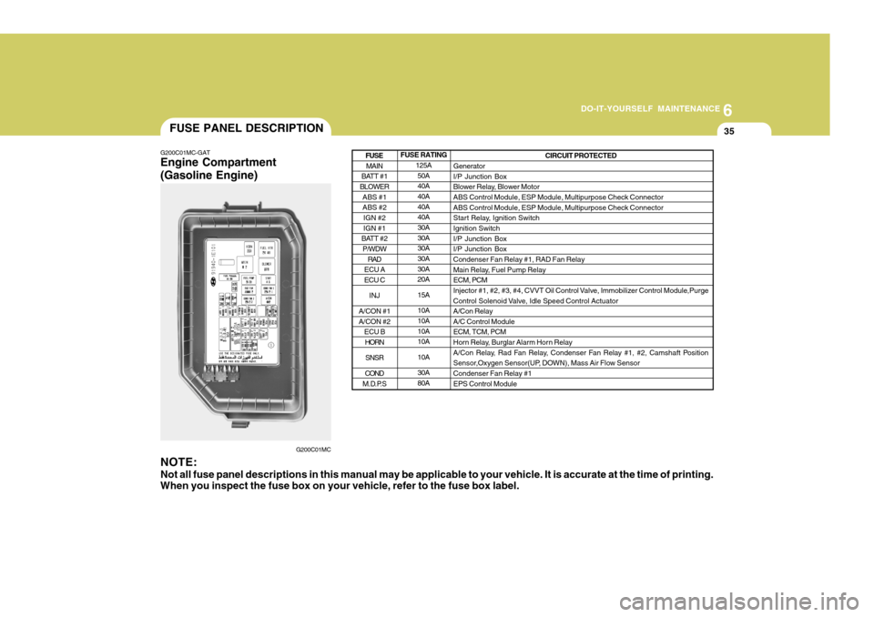
FUSE RATING 125A50A 40A 40A 40A40A 30A 30A30A 30A 30A20A 15A10A 10A 10A10A 10A30A 80A
G200C01MC-GAT Engine Compartment (Gasoline Engine)
G200C01MC
NOTE:
Not all fuse panel descriptions in this manual may be applicable to your vehicle. It is accurate at the time of printing.
When you inspect the fuse box on your vehicle, refer to the fuse box label. CIRCUIT PROTECTED
Generator I/P Junction Box
Blower Relay, Blower MotorABS Control Module, ESP Module, Multipurpose Check Connector ABS Control Module, ESP Module, Multipurpose Check Connector
Start Relay, Ignition SwitchIgnition Switch I/P Junction Box I/P Junction BoxCondenser Fan Relay #1, RAD Fan Relay
Main Relay, Fuel Pump Relay ECM, PCM
Injector #1, #2, #3, #4, CVVT Oil Control Valve, Immobilizer Control Module,Purge
Control Solenoid Valve, Idle Speed Control Actuator A/Con RelayA/C Control ModuleECM, TCM, PCM
Horn Relay, Burglar Alarm Horn Relay
A/Con Relay, Rad Fan Relay, Condenser Fan Relay #1, #2, Camshaft Position
Sensor,Oxygen Sensor(UP, DOWN), Mass Air Flow Sensor Condenser Fan Relay #1 EPS Control Module
MAIN
BATT #1
BLOWER
ABS #1 ABS #2IGN #2 IGN #1
BATT #2 P/WDW
RAD
ECU A ECU C
INJ
A/CON #1 A/CON #2 ECU BHORN
SNSR
COND
M.D.P.S
FUSE
FUSE PANEL DESCRIPTION
Page 262 of 284
6 DO-IT-YOURSELF MAINTENANCE
36
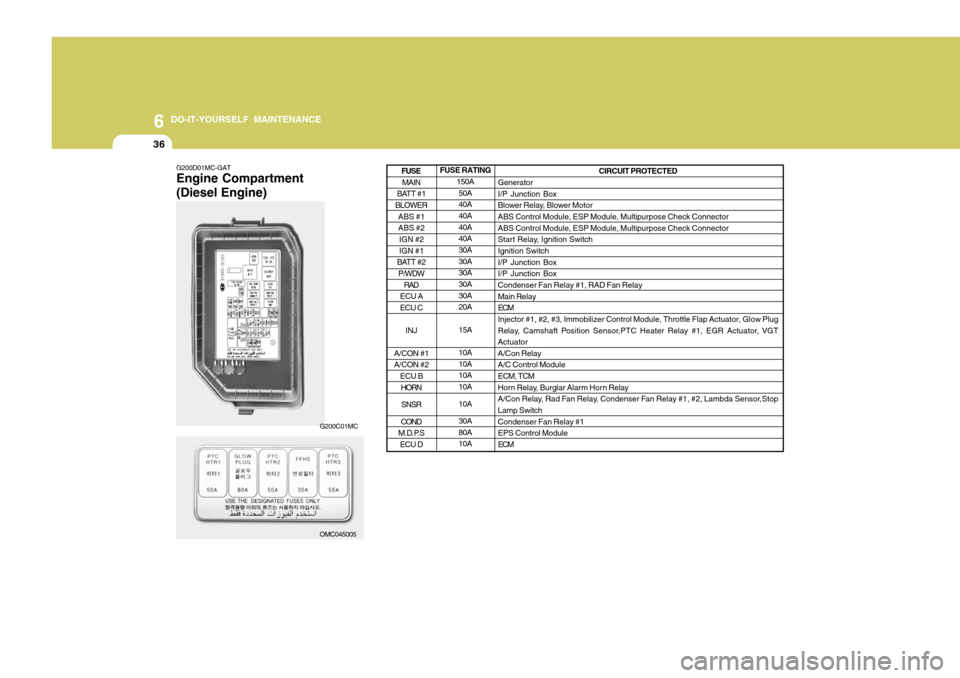
G200D01MC-GAT Engine Compartment (Diesel Engine) FUSE RATING
150A50A 40A 40A 40A40A 30A 30A30A 30A 30A20A 15A10A 10A10A 10A 10A30A 80A10A CIRCUIT PROTECTED
Generator I/P Junction Box
Blower Relay, Blower MotorABS Control Module, ESP Module, Multipurpose Check Connector ABS Control Module, ESP Module, Multipurpose Check Connector
Start Relay, Ignition SwitchIgnition Switch I/P Junction Box I/P Junction BoxCondenser Fan Relay #1, RAD Fan Relay Main Relay ECMInjector #1, #2, #3, Immobilizer Control Module, Throttle Flap Actuator, Glow Plug
Relay, Camshaft Position Sensor,PTC Heater Relay #1, EGR Actuator, VGT ActuatorA/Con RelayA/C Control Module ECM, TCM
Horn Relay, Burglar Alarm Horn Relay
A/Con Relay, Rad Fan Relay, Condenser Fan Relay #1, #2, Lambda Sensor,Stop Lamp Switch Condenser Fan Relay #1EPS Control Module ECM
MAIN
BATT #1
BLOWER
ABS #1 ABS #2IGN #2 IGN #1
BATT #2 P/WDW
RAD
ECU A ECU C
INJ
A/CON #1A/CON #2 ECU B
HORN
SNSR
COND
M.D.P.S ECU D
FUSE
OMC045005
G200C01MC
Page 282 of 284
10
INDEX
3
E Electronic Stability Program ...................................... 2-14
Emission Contro l System ............................................ 7-2
Engine Before starting the engine ....................................... 2-3
Compartment ........................................................... 6-2
Coolant ................................................................... 6-10
If the engine overheats ............................................. 3-4
Number ..................................................................... 8-3
Oil ............................................................................. 6-6 Starting ..................................................................... 2-5
Emergency Commodity ............................................. 3-12
Engine Exhaust Can Be Dangerous ............................ 2-2
F Floor Mat Anchor ..................................................... 1-101
Fog Light
Front ....................................................................... 1-83
Rear ........................................................................ 1-84
Front Seats Adjustable front seats ............................................. 1-17
Adjusting seat forward and rearward .......................1-17
Adjusting seatback angle ....................................... 1-17
Headrest ................................................................. 1-18
Seat warmer ........................................................... 1-20
Fuel Capacity ................................................................... 9-2
Gauge ..................................................................... 1-69
Recommendations .................................................... 1-2 Fuel Filler Lid
Remote release ...................................................... 1-97
Fuses ........................................................................ 6-20
Fuse Panel description .............................................. 6-35
G General Checks ........................................................... 6-5
Glove Box ................................................................. 1-91
H Hazard Warning System ............................................ 1-82
Headlight Aiming Adjustment..................................... 6-26
Headlight Leveling Device S ystem ............................1-82
Heating and Cooling Control ....................................1-105
Heating and Ventilation ............................................ 1-106
Air flow control ...................................................... 1-107
Air intake control .................................................. 1-106
Bi-level heati ng ..................................................... 1-110
Defrosting/Defogging ............................................. 1-110
Fan speed control ................................................. 1-106
Temperature control .............................................. 1-109
High-Mounted Rear Stop Light................................... 1-95
Hood Release ............................................................ 1-96
Horn ......................................................................... 1-104
I Immobilizer System ..................................................... 1-6
Instrument Cluster and Indicator Lights ..................... 1-56
Interior Light Interior light ............................................................. 1-90